
ステアリングナックルはシャフトではありません. ダクタイル鋳鉄の三次元構造部品です。, 鋳造アルミニウムまたは鍛造鋼 - その機能は、1 つの回転軸を共有しないいくつかの界面の相対的な形状に依存します。: ハブベアリングの穴とハブ面, ステアリングアームとタイロッドボス, ストラットまたはキングピンのインターフェイス, ブレーキキャリパーのボスとボールジョイントまたは車軸の開口部. したがって、ナックルを真っ直ぐにするということは、決して「1つの軸を真っすぐにする」という意味ではありません。. これは、フィーチャ間の一連の定義された角度および位置関係を復元することを意味します。.
実行可能なステアリングナックル矯正ソリューションは、機械や治具を指定する前に 5 つの質問に答える必要があります:
- ナックルは加工在庫が残っている生産部品ですか, 熱処理された加工中の部品, または損傷履歴のあるすでに完成した部品?
- データムチェーンを定義するフィーチャーセット - ハブボア, ハブ面, キングピンまたはストラットインターフェイス — そしてその順序?
- それぞれの偏差は体の全体的な歪みですか?, 1 つの境界面の角度の傾き, 曲がったステアリングアーム, または、矯正ではなくサイジングプロセスに属するボアの歪み?
- 材質や熱処理状態に対してどの修正ルートが認められているか: ツボ押し, 腕の矯正, 制御されたサイジング, またはスクラップ?
- ジオメトリはどのようにリリースされるか, 部品をリリースする前に、亀裂の完全性と加工後の安定性を検証する必要があります?
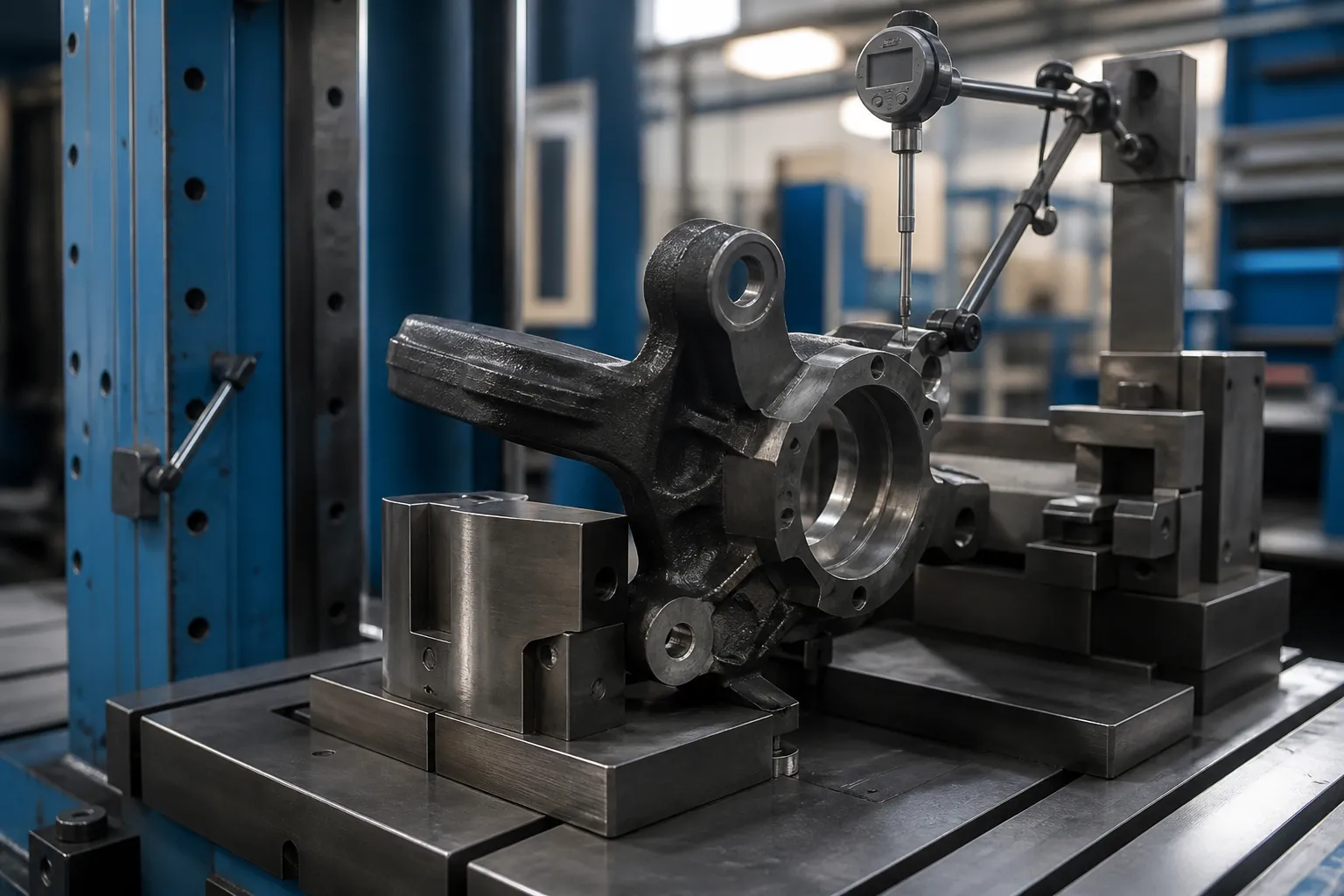
*エンジニアリングの概念図: 修正研究中にハブ面を監視するプローブを備えた部品固有の固定具に保持されたステアリング ナックル. お客様現場の写真ではありません. 力の位置, データムの選択と許容限界には、図面と代表的なサンプル部品が必要です。*
1 つのキーワードの背後に 2 つの異なる問題が隠れている
DataForSEO の結果 steering knuckle straightening 衝突修理と愛好家のフォーラムが大半を占めています: Redditのスレッドでは、ナックルワーク後に車が「まっすぐに走る」かどうかを尋ねる, ボブは石油野郎、曲がった関節を元に戻すことについて議論, Facebook グループの修理リクエスト. 唯一の実質的な技術ページは、SAI を使用したアライメント データからのナックル曲がりの診断に関する FenderBender の記事です。, キャンバーと夾角のグラフ - 衝突事故に関する結論は単刀直入です: キャストナックルは「修理不可能なので、損傷した場合は交換する必要があります。」
その教義は、その文脈(内部損傷が不明な衝突荷重の安全部品)にとっては正しいが、別の文脈では無関係である。: 歪みが測定される生産および再製造環境, 反復可能なプロセス成果物. これら 2 つの世界を 1 つのソリューション オファーに混在させてはなりません:
| ナックルの状況 | 歪みはどこから来るのか | エンジニア職 |
|---|---|---|
| 修理された車両の衝突で損傷したナックル | 衝撃過負荷, 不明な亀裂履歴 | 交換, まっすぐになっていない - この部品は文書化された安全コンポーネントです |
| ダクタイル鋳鉄または鍛造ナックルの製造中, 機械加工の前または間に | 鋳造または鍛造の応力緩和, 加工残留応力, 熱処理 | 検証されたプロセスウィンドウの下で測定可能な歪み補正 |
| アルミダイカストナックル (ストラットタイプ) 機械加工または熱老化後 | 加齢によるストレス解消, クエンチ歪み | 限定的なコールド補正; 合金および質別のリスク評価 |
| 再生ナックルコア | サービスウェア, 以前のクラッシュ, ベアリングの破損熱 | 全面検査ゲート: ひび割れ, 修正前の硬度と寸法 |
このページでは、2 行目とその隣接行について説明します。: 製造または再製造プロセス内でのナックルの歪み制御を測定. クラッシュで曲がったナックルを安全承認部品に戻すものは何もありません. 生産時に定期的に修正される隣接するシャーシコンポーネントの場合, 私たちのを参照してください シャーシシステム矯正の概要 との議論 3D ギガキャスト構造部品の矯正.
何よりも先にデータム チェーンを定義する
ナックルのすべての機能特徴をリスト化し、図面上のデータム参照フレームに結び付ける必要があります。:
- ハブベアリング穴 - 主軸データム A;
- ハブ面 - 二次平面データム B, ブレーキローターの振れを制御する;
- ステアリングアームの形状 - タイロッドボスの位置と高さ, リンケージ角度とトーの制御;
- キングピンボア (ソリッドアクスルナックル) ストラットフォークとか, ピンチボルトスロットと上部取り付け面 (マクファーソンナックル);
- 下部ボールジョイント開口部または圧入穴;
- ブレーキキャリパーブラケットボスとアバットメント面;
- ABS センサーのボアとフランジの詳細;
- プロセスデータム — 機械加工時に使用される位置決めパッドとクランプポイント.
ホイールとローターがハブボア上で回転するため、通常はハブボアがフレームを固定します。. FenderBender 診断ロジック - ステアリング軸の傾きからナックルの曲がりを推測, キャンバーと夾角の偏差 - 同じ形状の組み立てられた車両の影です: ハブボア軸がストラットまたはボールジョイントインターフェイスに対して傾いているナックルは、アライメント調整では吸収できない夾角誤差として表示されます。. 生産では、同じ偏差が車両ではなく部品上で直接測定されます。.
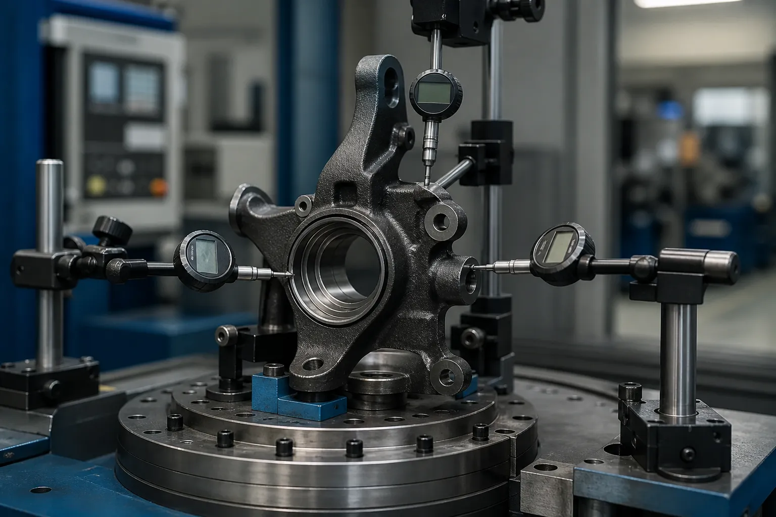
変形パターンを個別に認識する
「関節の曲がり」を一つの条件として扱うと間違った矯正が生じる. 実際には 4 つのパターンが主流です, それぞれが異なる機能的結果と異なる修正ルートを持ちます:
| パターン | サイン | 機能的な結果 |
|---|---|---|
| ボア軸に対するハブ面の傾き | ボアをパイロットした場合のハブ面の面振れ | ブレーキローターの振れ, 厚さの変化, ブレーキジャダー |
| サスペンションインターフェースに対するハブボアの角度偏差 | サイ / データム フィーチャ間で測定された夾角タイプの誤差 | アライメントアウトできないキャンバー; タイヤの摩耗 |
| ステアリングアームを曲げたりひねったりする | タイロッドボスがアーム根元に対して変位または回転 | トーとアッカーマンのエラー; 負荷による腕の疲労 |
| 穴の歪みやボスの位置ずれ | 圧入部の真円度や位置誤差 | ベアリングの取り付けとキャリパーのボルトアップの問題; サイズに属します, 曲がらない |
最初の 2 つは、ボディ ジオメトリの真の矯正問題です。. 3 つ目は、独自のサポートと負荷計画を備えた局所的な腕の矯正です。. 4 番目の作業は、サイジングまたはキャリブレーション作業に送られる必要があります。「真っ直ぐにしながら」ボアを丸く押すと、組み立て後に再発する嵌合の問題が隠蔽される危険があります。. 同じ分離ロジックが、関連するステアリング ライン コンポーネントにも適用されます。 自動ステアリングラック矯正工程 そして ロングボールスタッド修正.
測定戦略: 比較, それから絶対
衝突診断は工場に図面データが存在しないため、対向部品や共線図との比較測定. 生産測定はその妥協を継承すべきではありません. 正しい順序は:
- ハブボア上の部品をパイロットします (または加工基準穴) 回転治具内で.
- ハブ面の面振れを調べ、ステアリング アーム パッドとタイロッド ボスの位置と高さを調べます。.
- キングピンまたはストラットのデータム フィーチャをキャプチャします - マンドレルの穴, またはシミュレートされた嵌合面上のストラットフォーク.
- ゴールデンサンプルまたは CMM マスター値と比較する, 反対側の部分に反しないでください.
- 修正を試みる前に、各フィーチャの偏差の大きさと方向を記録します。.
少量のリマン作業に, 高さゲージ付きの花崗岩プレートと家族ごとの CMM レポートで十分な場合があります. 生産量について, 治具はロータリーインデックスマシンのステーションになります: 多点電子プローブ, サーボプレスヘッド, 補正量を決定する前に各部の偏差マップを記憶するコントローラー. 補正前のマップは官僚主義ではありません。それがなければ、体の全体的な歪みと腕の局所的なエラーを区別する方法がありません。, 間違った機能がロードされてしまう.
修正ルートとその限界

ダクタイル鋳鉄および鍛造鋼ナックル
これらの材料は、補正ウィンドウが検証されている場合、制御されたコールド ポイント プレスに耐えます。. 印刷機の能力よりも積載計画の方が重要です: 剛性ボス構造の下でサポート, 修正されるフィーチャまたはその近くに適用される荷重, ストロークごとにスプリングバックを測定したショートストローク. 修正は反復的です — を押してください, リリース, 再測定 - 鋳物は応力を不均一に解放するため, アームでの修正によりハブ面の読み取り値が変わる可能性があります. 各サイクル後に完全なプローブ マップを繰り返します, ロードされた 1 つの機能だけではありません.
鋳造アルミニウムナックル
T6/T7 タイプの焼き戻しのダイカスト アルミニウム ナックルは延性が低く、制御されていない冷間曲げでは亀裂が発生するという定評があります。. 訂正, まったく承認されている場合, 角度が小さい, 低速, 犠牲サンプルで合金および焼き戻しごとに検証されています, 多くの場合、その後に安定化処理が行われます. 多くのアルミニウム ナックル プログラムは、単に上流のプロセス制御を厳しく設定し、代わりに歪みをスクラップするだけです。その決定は冶金学者に属します。, 機械ベンダーにではなく.
押しても直らない箇所
ステアリングアームに曲げ過負荷がかかると疲労と責任が問われる, 幾何学の質問ではありません. 完成した安全部品に衝突荷重がかかったアームの修正は、たとえジオメトリが直後に読み取られたとしても、検討の対象外であるべきです。衝突業界が適用するのと同じ交換原則です。. 矯正は、負荷履歴が既知であり、補正ウィンドウが検証されている場合、プロセスに起因する歪みに対してその役割を果たします。.
受付ゲート

ナックルのリリースされた矯正プロセスには 4 つのゲートが必要です, 順番に:
- プレゲート: 亀裂検出 (鉄部品用の磁性粒子または同等品) 修正前 - 既存の亀裂を真っすぐに直すと、証拠と部品が破壊されます。.
- ジオメトリゲート: 図面限界内の完全なデータムフィーチャーマップ - ハブ面の振れ, ボアとサスペンションの角度, 腕の位置 — 矯正後、応力除去または安定化ステップ後に測定.
- 安定ゲート: 次の加工または加熱操作後の再測定; リラックスして戻す修正は応力の重ね合わせでした, 修正ではない.
- トレーサビリティゲート: 各部偏差マップ, シリアル番号と照らし合わせて保存される補正回数と最終測定値, 再加工制限が定義されており、それを超えると部品は再度プレスされずに廃棄されます。.
やり直しの限界を正直に定義すること、そしてそれに関連する NOK 仕分けルールを定義することが、直線化ラインとコーナーでのプレスを分けるものです. 当社の概要 直線化ラインにおける NOK の選別と再加工の制限 意思決定構造をカバーする.
よくある落とし穴
- 間違ったデータム順序. ボアが機能軸であるときにハブ面を修正すると、1 つのチェックに合格し、組み立てに失敗した部品が生成されます。.
- 1 つの特徴の再測定. 修正されたフィーチャのみをチェックすると、ボディ上の他の場所で相互に結合したシフトが非表示になります。.
- オーバープレス鋳物. 重いストロークで 1 ミリメートルの最後の部分を追いかけると、目に見える形状が目に見えない微小亀裂と引き換えになります。.
- 安定性の再チェックをスキップする. 次の機械加工後に戻る歪みは、緩和されていない残留応力の典型的な兆候です。, そしてそれは顧客の前に現れます, あなたのセルにはいない.
- 修正前はクラックゲートなし. 既存の亀裂は、文書化された原因としての修正ストロークによりフィールド故障になります。.
修正する前にプロセス段階をフリーズする
ルート内で修正がいつ行われるかは、修正がどのように行われるかと同じくらい決定的です. 鋳造または鍛造直後に測定されたナックルには、加工中に部分的に緩和される在庫変動と残留応力が伴います。; その段階で最終的な形状に修正するということは、変化しようとしているボディを修正することを意味します. 実用的なウィンドウは次のとおりです。:
- 荒加工後, セミフィニッシュ前: 機能的なデータム フィーチャが存在し、在庫が残っている - 通常は最適なウィンドウ, なぜなら、修正は研削とボーリングと戦うのではなくサポートするからです。.
- ハブ穴の熱処理または高周波焼入れ後: 歪みはピークに達しており、検証された補正により、廃棄されるはずだった部分が復元されます。, ただし、材料の状態によりウィンドウが制限されます.
- 仕上げ加工後: 補正は小さな角度偏差に限定されます; 安定ゲートのあらゆるリスクが適用され、その見返りがそれを正当化する必要があります.
「ストレート」の意味も舞台が決める. 退屈を終える前に, ハブボアはまだ最終ではないため、データムは機械加工データムから取得する必要があります; 退屈を終えた後, ボア自体が正直な基準になります. プロセスポイントの名前が記載されていない矯正仕様書は、2 つの部門で異なる解釈がされる仕様書です。これが、部品が間違った段階で正しく修正されても、組み立て時に失敗する仕組みです。.
重大な調査の内容
ナックル矯正ステーションに責任を持って見積もりを依頼するには, サプライヤーが必要とする: データムスキームと公差シートを含む図面; 修正点の材質と熱処理状態; 今日はどこで歪みが測定され、どのような結果が分布したのか; サンプルパーツカバー良好, 境界線と NOK 条件; 必要なサイクルタイム; 工場が受け入れる再加工と廃棄のルール. これらの入力により、フィクスチャのコンセプトが完成します。, プローブ計画とプレス アーキテクチャは、それらを使用せずに直接続きます。, マシンの提案は、どの機能が実際に「ストレート」を定義するかについての推測です。.
Still weighing options for steering knuckle straightening? の シャフト用機械選定ガイド, チューブとプロファイル そして 矯正機の価格の内訳 are written for exactly this stage of the decision.