
Az elektromos motor forgórésze nem egyszerűen egy motor tengelye extra tömeggel. Egyszer egy laminált mag, mókusketrec, kommutátor, mágnestartó vagy más rotorcsomag van a tengelyre szerelve, a munkadarab új funkcionális felületeket kapott, törékeny régiók, hőtörténet és kiegyensúlyozatlan viselkedés. Megnyomása, zsugorított illesztés, fröccsöntés, hegesztés, keményforrasztás, A hőkezelés és a végső megmunkálás mind megváltoztathatja a két csapágycsap és a rotortest közötti kapcsolatot.
Egy megbízható villanymotoros forgórész egyengető megoldásnak ezért a teljes összeszerelési állapotot kell szabályoznia: csapágy-napló tengely, rotor-mag kifutás, látható tengelygeometria, védett érintésmentes régiók, visszaugrás, kiadott mérés és az egyenesítés közötti sorrend, fejezze be az esztergálást és a kiegyensúlyozást.
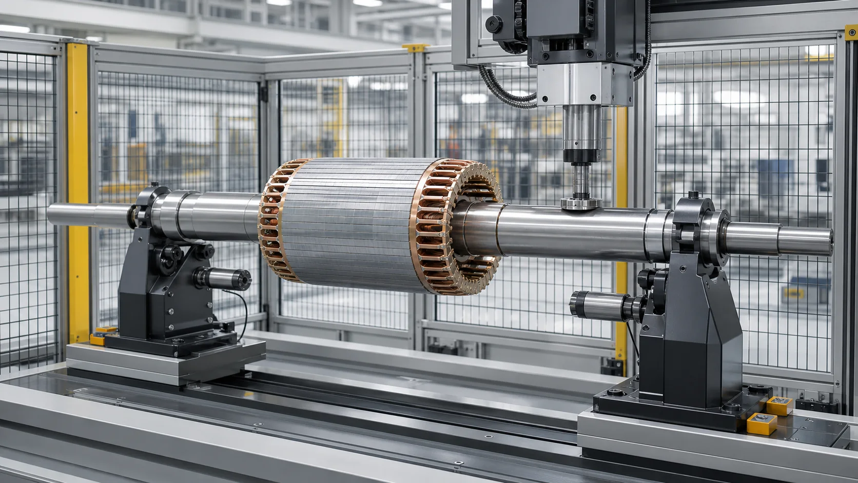
Ez egy mérnöki koncepció illusztráció, nem ügyféloldali fénykép. A rotor tényleges felépítése, szerszámozás, időpont terv, A korrekciós erő és az automatizálási szint rajzokat és reprezentatív mintavizsgálatokat igényel.
Komplett forgórész a csupasz motortengelyhez képest
Az első projektdöntés az, hogy a cél egy tengely vagy egy összeszerelt rotor.
| Munkadarab állapota | Fő geometriai kérdés | Dedikált folyamat |
|---|---|---|
| Csupasz motortengely | Elfogadható-e a tengely tengelye a rotor összeszerelése előtt?? | Központok, csapágyülések, bordás/menet/kulcshorony és hőkezelési torzítás |
| Tengely rotorcsomaggal | Mindkét csapágycsap egy vonalban van a mag/ketrec/mágnes összeszerelése után? | Rotor-csomag védelem, hozzáadott merevség, összeszerelés okozta hajlítási és egyensúlyozási sorrend |
| Rotor forgás befejezése után | Összefüggenek-e a csapok és a forgórész külső átmérője a végső nullapont állapotában? | Kész felületvédelem és minimális megengedett korrekció |
| Komplett motor | Az összeszerelt motor találkozik-e a vibrációval, zaj, áram- és hőmérsékleti követelmények? | Rendszerteszt; nem egyengetőgépes elfogadás önmagában |
A meglévő csupasz tengelyre vonatkozó követelmények a Automatikus motortengely-egyenesítő megoldás. Ez az oldal az összeszerelt forgórészre vagy armatúrára vonatkozik, az állórész és a motorházba történő beszerelés előtt.
Határozza meg a rotorcsaládot
A „motorrotor” kifejezés nagyon különböző munkadarabokat takar. A javaslatnak azonosítania kell:
- mókuskalitkás indukciós rotor öntött vagy gyártott véggyűrűkkel;
- tekercselt rotor vagy elektromos armatúra;
- állandó mágneses vagy szinkron rotor;
- vontatómotoros rotor;
- generátor rotor;
- rotor kommutátorral, csúszógyűrűk, ventilátor, kódoló sáv vagy csatolási funkció;
- tömör tengely, üreges tengely vagy hűtőjárat;
- egyrészes, sajtolt, zsugorított, hegesztett vagy más módon összeszerelt rotorcsomag;
- lágyan megmunkált, hőkezelt, cél-föld, bevont vagy kiegyensúlyozott állapot;
- Rotor szabad korrekciós fesztávval, szemben a biztonságos szabad tengelyzóna nélküli kialakítással.
Nem minden rotort lehet nyomással kiegyenesíteni összeszerelés után. Állandó mágnesek, rögzítő ujjak, tekercsek, szigetelés, a keményforrasztott kötések és a nagy interferenciát okozó interfészek szigorú erőt okozhatnak, hőmérsékleti és mágneses kezelési határértékek. A megvalósíthatóságot a tényleges kivitelezésre vonatkozóan igazolni kell.
Fagyassza le a gyártási szakaszt
Tengely a rotor összeszerelése előtt
Ez egy csupasz tengelyű projekt. A javításhoz való hozzáférés általában a legjobb, de nem tudja eltávolítani a későbbi interferenciaillesztés okozta torzulást, zsugorítási folyamat, présöntvény vagy rotor-csomag összeállítás.
Rotor-Pack összeszerelés után, Az esztergálás befejezése előtt
A teljes összeszerelési hatás jelen van, míg a megmunkálási anyag a csapokon vagy a forgórész külső átmérőjén maradhat. Galdabini a rotor egyengetését úgy írja le, mint a csapágyülés geometriájának javítását az elfordulás előtt, és csökkenti a szükségtelen leforgácsolást. Ez egy folyamattervezési elv, nem univerzális anyagtakarékossági garancia.
Az esztergálás vagy köszörülés befejezése után
A csapágynaplók, a vállak és a rotor felülete elkészült. A szerszám érintkezési és bemélyedési határai kritikussá válnak, és csak engedélyezett szabad tengelyfesztávok használhatók a korrekcióhoz.
Egyensúlyozás után
Az egyengetés megváltoztathatja a forgórész tengelyét, a naplókhoz viszonyított tömegeloszlás és a korábban mért kiegyensúlyozatlanság. A kiegyensúlyozás után korrigált rotornak vissza kell térnie a meghatározott egyensúly-ellenőrzési útvonalra.
| Színpad | Előny | Fő kockázat | Szükséges újraellenőrzés |
|---|---|---|---|
| Csupasz tengely | Maximális korrekciós hozzáférés | A későbbi rotor-szerelvény visszavezetheti a hajlítást | Összeszerelés után mérje meg újra |
| A rotor összeszerelve, készlet marad | Az összeszerelés okozta hajlítás látható | A rotorcsomagot és a végelemeket védeni kell | Befejezés-megmunkálás összefüggés |
| Készre megmunkált rotor | Funkcionális nullpontok állnak rendelkezésre | Felületi sérülések és korlátozott biztonságos préselési zónák | Teljes geometria és felület vizsgálat |
| Korábban kiegyensúlyozott rotor | Meglévő egyenlegadatok állnak rendelkezésre | A kiegyenesítés érvénytelenítheti | Végső egyenleg ellenőrzése |
Határozza meg, mit vezérel a rajz
A „rotor lefutása” nem kezelhető egyetlen osztatlan értékként. A vonatkozó jellemzők lehetnek:
- az egyes csapágycsapok radiális kifutása;
- koaxiális kapcsolat a két csapágy-napló tengelye között;
- tengelyhosszabbítások kifutása, pecsétnyomok, ülések vagy kódoló pályák összekapcsolására;
- rotormag külső átmérőjű kifutása a csapágy tengelyéhez képest;
- kommutátor vagy csúszógyűrűs lefutás;
- váll arc kifutás;
- szabaddá tett tengelyfesztáv egyenessége;
- az egyes folyóiratok kereksége és hengeressége;
- rotor-csomag axiális helyzet, verem állapota és a véggyűrű integritása;
- statikus és páros kiegyensúlyozatlanság meghatározott korrekciós síkban;
- kész motorvibráció, zaj és elektromos teljesítmény.
Használja a Tengely egyenesség vs kifutás vs TIR vezető forma elkülönítésére, származtatott tengely és forgásjelzés. Az egyenesítés megváltoztathatja a globális tengelyviszonyokat; nem korrigálja automatikusan a napló kerekségét, rotor-stack geometria, elektromos hibák vagy tömegkiegyensúlyozatlanság.
Állítsa be a funkcionális nullpontot
A legtöbb összeszerelt rotorhoz, a két csapágycsap központi helyen van a beépített forgástengelyen. Az SKF elektromos motor csapágyvezetése szabályozott geometriai jellemzőként kezeli a tengelycsapágyüléseket és az ütközővállakat, és kifejezetten magában foglalja a radiális és axiális kifutási szempontokat. A projektnek továbbra is követnie kell az ügyfél rajzát és a kiválasztott csapágyrendszert.
A megoldásnak megkülönböztetnie kell:
- rajzi nullapontok és funkcionális csapágytengely;
- esztergálásra vagy köszörülésre használt gyártóközpontok;
- egyengetőgép-támaszok és forgóeszközök;
- szenzorpályák, amelyeket a csap és a rotor-test lefutásának rekonstruálására használnak;
- kiegyensúlyozó gép támaszok és korrekciós síkok;
- végső motor összeállítás és teszt referenciák.
A központok hasznosak lehetnek a megmunkálásnál, de egy középen meghatározott tengely nem egyezik automatikusan a kész csapágycsapok által meghatározott tengellyel. Hasonlóképpen, a rotor ismételt alátámasztása nem bizonyítja, hogy a támasztékok reprodukálják az ügyfél csapágyállapotát.

Ez a mérnöki koncepció illusztráció több mérési pályát mutat be. Nem ír elő érintkezőérzékelőket a rotorcsomagon vagy egyetlen univerzális támasztóelrendezést.
| Mérési pálya | Fő kimenet | Értelmezési kockázat |
|---|---|---|
| Csapágynaplók | Funkcionális forgástengely és naplófutás | Helyi kerekség, szennyeződés vagy szonda erő torzíthatja az eredményt |
| Tengelyhosszabbítások | Hajlítsa meg a csapágyakon kívül | Kulcshornyok, szálak és spline-ok hamis jelet hoznak létre |
| Rotormag külső átmérője | Mag- és folyóirat kapcsolat | A laminálás lépései, a rések és a szándékos felületi jellemzők maszkolást igényelnek |
| Kommutátor vagy csúszógyűrűk | Funkció kifutása | A törékeny felületek érintésmentes érzékelést igényelhetnek |
| Vállak és arcok | Axiális kifutás | A letöréseket és az élek sérülését ki kell zárni |
| Mérleg referenciajel | Szögkorreláció | A jel a szöget jelöli, nem geometriai megfelelőség |
Különítse el a rotormag jelét a tengelykanyarból
A laminált rotorfelület nem mindig sima hengeres alappont. Slots, ferde, laminálás lépései, öntött véggyűrűket, kiegyensúlyozó vágások, ragasztóanyag, bevonatok és helyi felületi eltérések jelenhetnek meg az érzékelő nyomában.
Az algoritmusnak kell:
- azonosítsa a rotor típusát és a szögreferenciát;
- maszk rések, kulcshornyok, szálak, lyukak és egyensúly-korrekciós területek;
- használjon több szöghelyzetet az ismételhető forma és a globális hajlítás elkülönítésére;
- értékelje mindkét csapágycsapot és legalább a rajz szempontjából releváns forgórész jellemzőt;
- ne alakítsa át a helyi laminálási vagy véggyűrűs jelet erős nyomásparancsgá;
- ha szükséges, hasonlítsa össze a kiadott eredményt független mérőeszközzel vagy kiegyensúlyozó támasztékkal.
Ha a forgórész külső átmérőjét egyengetés után a csapokhoz képest simára esztergálják, az átvételi tervben fel kell tüntetni, hogy melyik geometria a köztes és melyik a végleges.
Védje a rotorcsomagot és az elektromos jellemzőket
A rotorcsomagot általában tiltott korrekciós érintkezőként kell kezelni, kivéve, ha a tervezés tulajdonosa kifejezetten jóváhagy egy erre a célra szolgáló rögzítést..
Tipikus No-press és No-Support zónák
- laminált mag és forgórész hornyok;
- mókusketrec rudak és véggyűrűk;
- állandó mágnesek és tartóhüvelyek;
- tekercsek, szigetelés és szalagozás;
- kommutátor és csúszógyűrűk;
- rajongók, kódolók és érzékelősávok;
- csapágynaplókat, tömítse a pályákat és kész interferencia illesztéseket;
- vállak, filézések és szakaszátmenetek;
- kulcshornyok, spline, szálak, keresztfuratok és hűtőjáratok;
- hegesztési varratok, forrasztott kötések és helyileg edzett zónák.
Biztonságos terhelési útvonal alapelvei
- csak a rajz által jóváhagyott szabad tengelyfesztávokon helyes;
- használjon széles sugarú cipőket és támasztékokat, amelyek megfelelnek a tengely átmérőjének;
- tartsa a rotor köteget a közvetlen présterhelési útvonalon kívül;
- megakadályozza az élek terhelését a vállak közelében, és illeszkedjen az átmenetekhez;
- figyelje az erőt és az elmozdulást a teljes löket során;
- hagyja abba a kóros merevséget, csúszás vagy érzékelő viselkedése;
- korlátozza a korrekciós számot és a felhalmozott képlékeny feszültséget;
- teljesen engedje el az eredmény értékelése előtt.
Egyes kompakt rotoroknak nincs elég hosszú tengelytávja a biztonságos hárompontos korrekcióhoz. A helyes döntés lehet a csupasz tengely korábbi kiegyenesítése, módosítsa az összeszerelési útvonalat, használjon más korrekciós koncepciót, vagy utasítsa el az összeállítást.
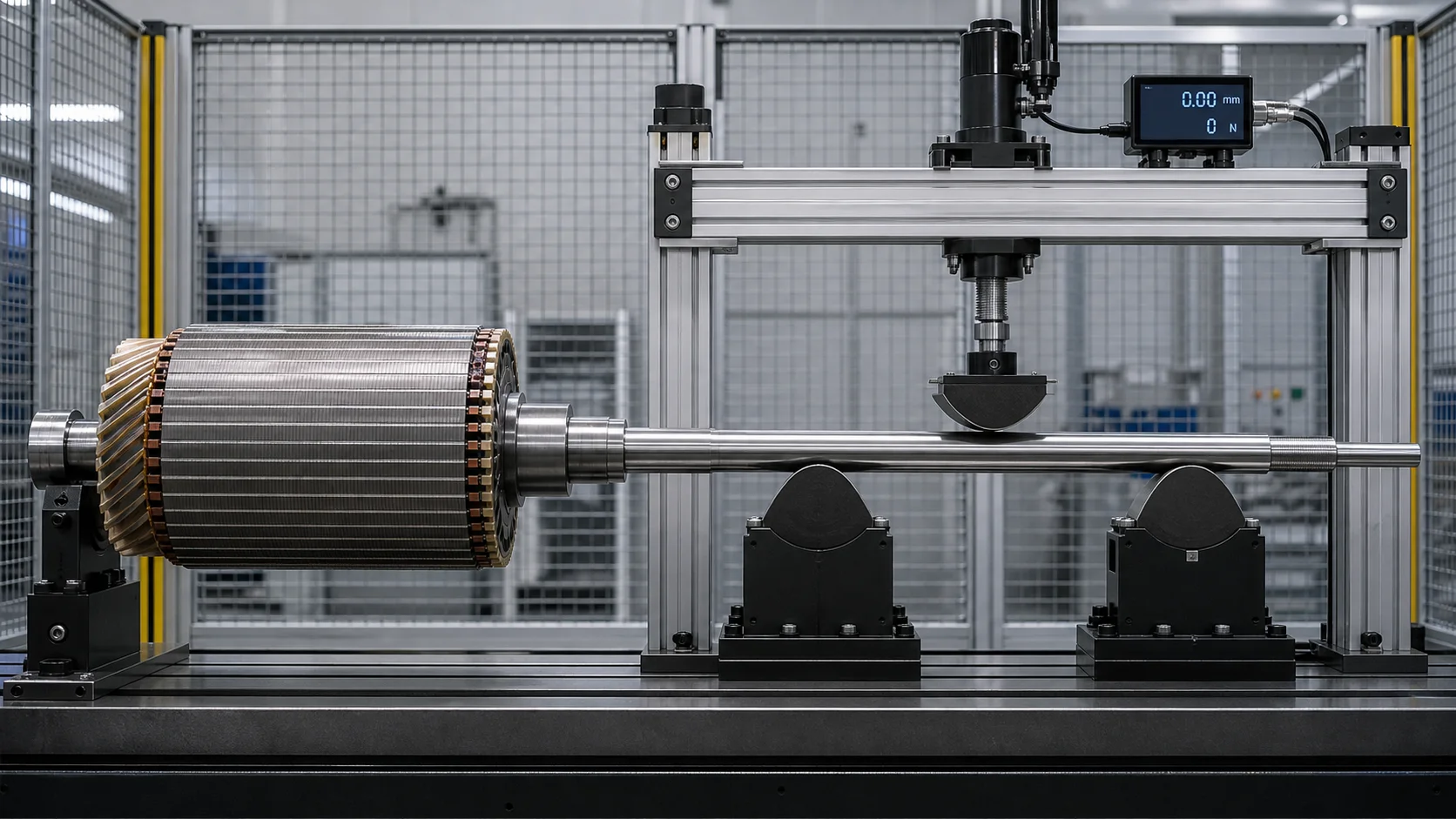
Ez a koncepció-illusztráció szándékosan a rotorcsomagot a préskereten kívül tartja, és a hárompontos terhelést csak egy szabad tengelytávra fejti ki.. A tényleges támogatási koordináták, a cipősugár és az erőhatárok reprezentatív mintákat igényelnek.
Az egyenesség és az egyensúly más
Az egyengetés és az egyensúlyozás különböző fizikai problémákat old meg.
| Állapot | Geometriai mérés | Kiegyensúlyozó mérés | Helyes válasz |
|---|---|---|---|
| Hajlított tengelytengely | Érzékeli a napló/tengely/mag kifutási kapcsolatot | Sebességfüggő vibráció vagy kiegyensúlyozatlanság jelként jelenhet meg | Javítsa meg a geometriát, ha a rotor a jóváhagyott burkolaton belül van |
| Tömegkiegyensúlyozatlanság egyenes naplókkal | A geometria áthaladhat | Érzékeli a nagyságot és a szöghelyzetet egy vagy több síkban | Távolítsa el/adja hozzá a tömeget a jóváhagyott mérlegmódszerrel |
| Helyi napló űrlap hiba | Érzékeli a kerekség/hengeresség problémáját | Megzavarhatja a támogató viselkedést | Géppel vagy selejt; ne kezelje globális kanyarként |
| A rotormag excentricitása a csapokhoz | A mag kifutása eltér a napló tengelyétől | Hozzájárulhat a kiegyensúlyozatlansághoz és az elektromágneses hatásokhoz | Határozza meg, hogy a geometria, a megmunkálás vagy összeszerelés a felelős |
| Termikus íj | A hideg geometria eltérhet az üzemállapottól | Változhat sebességgel és hőmérséklettel | Termikus/üzemállapot-technikát igényel, nem vak hideg korrekció |
A Schenck kiegyensúlyozási vezetése támogatja a rotorokat a saját csapjaikon, és meghatározott síkokban méri a kiegyensúlyozatlanságot. Ez más művelet, mint egy hajlított tengely rekonstrukciója és a préselés korrekciója. A kiegyensúlyozás nem teszi egyenessé a meggörbült rotort, míg az egyengetés nem teszi kiegyensúlyozottá a rotort.
Ajánlott sorozat
- létrehozza az összeállítási szakaszt és a funkcionális naplóadatot;
- mérje meg a felszabaduló geometriát;
- csak az engedélyezett zónák és anyaghatárokon belül egyenesítse ki;
- Mérje meg újra az összes geometriát a kiadás után;
- a tervezett helyen fejezze be a végső megmunkálást;
- végezze el vagy ellenőrizze a kiegyensúlyozást a kívánt síkban;
- fejezze be a végső rotor- és motorteszteket.
Ha a gyártási megszorítások újabb rendelést igényelnek, az érvényesítési tervnek meg kell mutatnia, hogy a későbbi műveletek hogyan befolyásolják mind a geometriát, mind az egyensúlyt.
Támogatás befolyásának és kiadott mérésének szabályozása
A rotor tömege, a támasztávolság és a napló állapota befolyásolja a megfigyelt görbét. A cellának meg kell határoznia:
- pontos naplótámasz pozíciók és görgős profil;
- a rotor orientációja és a szög indexelési sorrendje;
- érintkezési nyomás és felületvédelem;
- érzékelő erő vagy érintésmentes leállás;
- megereszkedés kezelés hosszú vagy nehéz rotorokhoz;
- hőmérséklet stabilizálás;
- terhelt versus kiengedett mérési állapot;
- összefüggés a kiegyenlítő géppel és a motor végső mérőeszközével.
A Schenck dokumentálja a rotorok kiegyensúlyozását saját tengelycsapjaikon görgő vagy más alkalmazás-specifikus támasztékok segítségével. Az átvihető alapelv az, hogy a támogatási feltétel része a mérési meghatározásnak; a kiegyensúlyozó gép kialakítása és teljesítményadatai nem a StraighteningTech képességekre vonatkozó állítások.
Zárt hurkú rotor egyenesítési eljárás
1. Azonosítsa a rotort
Válassza ki az érvényes receptet a cikkszámból, rotor felépítése, szerelési szakasz, anyagállapot és rajzfelülvizsgálat.
2. Vizsgálja meg és tisztítsa meg
Ellenőrizze a naplókat, kulcshornyok, véggyűrűk, laminálások, mágnesek/hüvelyek, kommutátor, egyenlegcsökkentések és egyéb elutasítási feltételek. Tisztítsa meg a jóváhagyott támasztó- és mérőpályákat.
3. Betöltés a jóváhagyott naplókon vagy folyamatidőpontokon
Erősítse meg a rotor irányát, ülés és szögreferencia a kész felületek húzása nélkül.
4. Mérje meg az összes ellenőrzött pályát
Forgassa el a forgórészt, és rekonstruálja a csapágy-naptár tengelyét, kitett tengelygörbe és a rajz szempontjából releváns rotor-test kapcsolat. A maszk megszakadásai.
5. Osztályozza az eltérést
Különítse el a javítható globális hajlítást a helyi formahibától, laza összeszerelés, rotor-csomag excentricitás, elektromos sérülés vagy tömegkiegyensúlyozatlanság.
6. Válasszon egy biztonságos korrekciós tartományt
Csak engedélyezett szabad tengelyzónákat használjon. Erősítse meg a támogatási tartományt, korrekciós irány, erő/elmozdulás határértékei és a rotor-köteg hézaga.
7. Alkalmazza a szabályozott korrekciót
Használja az érvényesített rugós modellt, figyelje az erőt és az elmozdulást, és állítsa le a rendellenes jeleket.
8. Teljesen engedje fel és mérje újra
Ítélje meg a terheletlen rotort. Ellenőrizze újra a naplókat, tengelyhosszabbítások és forgórész-test nyomvonalak, mert egy korrekció több kapcsolatot is elmozdíthat.
9. Vizsgálja meg és irányítsa
Végezze el a szükséges felületet, repedés, elektromos és szerelési ellenőrzések. Vezesse be a rotorokat a végső megmunkáláshoz vagy kiegyensúlyozáshoz; az abnormális alkatrészeket a műszaki átvizsgálásra irányítani.
10. Rögzítse az eredményt
Tárolja a rotor azonosítóját, recept átdolgozása, térképek előtt/utána, korrekciós koordináták, erő-elmozdulás görbék, riasztások és elhelyezés, ha nyomon követhetőség szükséges.
Javasolt cellakonfiguráció
Egy projektspecifikus rotorcella tartalmazhat:
- mintaerőadatokból kiválasztott elektromechanikus vagy hidraulikus prés;
- védett naplógörgők, központok vagy egyedi forgási szerelvények;
- érintkező vagy érintésmentes érzékelők naplókhoz, tengelyhosszabbítások és rotortest;
- szögindexelés és jellemzőmaszkolás;
- cserélhető széles sugarú szerszámok hibabiztos beállítással;
- őrzött automata vagy kezelői rakodás;
- erő, elmozdulás és receptszabályozás;
- kiadott állapotú újramérés;
- alkatrész azonosítás és nyomon követhetőség;
- interfészek a megmunkálás befejezéséhez, kiegyensúlyozó és minőségi rendszerek.
Galdabini felsorolja a kézikönyvet, lánc/villa, portál és robot rakodási koncepciók elektromos rotorokhoz. A végső automatizálási szintnek követnie kell a valódi rotortömeget, változatszám, felületi érzékenység és termelési áramlás.
Mintavizsgálat és elfogadás
A reprezentatív mintamátrixnak le kell fednie:
- legkisebb és legnagyobb tengely és rotor-mag átmérő;
- minimális és maximális rotorhossz és tömeg;
- minden forgórész építési és összeszerelési mód;
- tömör és üreges tengelyek, ahol lehetséges;
- anyag és hőkezelési állapotok;
- minimális és maximális bejövő kanyar;
- minden kitett korrekciós tartomány és tiltott zóna;
- naplók a megmunkálás befejezése előtt és után;
- rotor-mag, kommutátor, csúszógyűrűs vagy kódoló funkciók;
- korábban kiegyensúlyozott és kiegyensúlyozatlan minták;
- ügyfélmérő és kiegyensúlyozó-gép összefüggés;
- felület, repedés, elektromos és szerelési ellenőrzés javítás után.
Használja a Egyenesítő minta vizsgálati és elfogadási útmutató a megvalósíthatóság elkülönítésére, ZSÍR, SAT és gyártási képesség. A gépkatalógus értéke nem bizonyíték egy adott rotorcsaládra.
A műszaki ajánlathoz szükséges adatok
Kérjük, adja meg:
- rotor összeállítási és tengelyrajzok;
- rotor típusa, szerelési mód és gyártási mód;
- anyag, hőkezelés, keménység és felületi állapot;
- alkatrész változatok, tömeg, hossza és a rotormag átmérője;
- egyengető szakasz az összeszereléshez képest, megmunkálás és kiegyensúlyozás;
- rajzi nullapontok és szabályozott kifutási/egyenességi jellemzők;
- bejövő eltérés-eloszlás és ismert összeállítás-torzulás;
- jóváhagyott támogatási és sajtózónák;
- védett laminálások, gyűrűk, mágnesek, tekercsek, kulcshornyok és kész illesztések;
- korrekció-számlálás, repedés, elektromos és felületi határértékek;
- kiegyensúlyozó síkok, módszer és a szükséges újraellenőrzés;
- vásárlói nyomtáv és végső motorteszt követelményei;
- automatizálás, nyomon követhetőségi és jelentési követelmények;
- reprezentatív minták a vizsgálatokhoz.
Gyakran Ismételt Kérdések
Rányomhatja-e a prés a rotor laminálásait?
Ne feltételezd. Laminálások, ketrecrudak, véggyűrűk, A mágnesek és tekercsek működőképesek és sérülésérzékenyek. Az alapértelmezett koncepció a korrekciós terhelési útvonalon kívül tartja őket, hacsak a rotor tervezője nem hagy jóvá egy dedikált rögzítést és érvényesítést.
Kiegyenesíteni kell a kiegyensúlyozás előtt vagy után?
A geometriát általában a végső kiegyensúlyozás előtt kell megállapítani. Ha egy rotort kiegyensúlyozás után kiegyenesítenek, az egyensúlyi feltételt újra ellenőrizni kell, mert a forgástengely és a tömeg összefüggés megváltozhatott.
Egy cella képes csupasz tengelyeket és komplett rotorokat feldolgozni?
Esetleg, de csak külön receptekkel, támogatja, szenzornyomok, szerszámtérképek és érvényesítés. A teljes rotor tömeget ad, merevség, törékeny vonások és egyensúlyi felelősség.
Az alacsony vibráció bizonyítja, hogy a rotor egyenes??
Nem. A vibráció az egyensúlytól függ, csapágyak, tartószerkezet, elektromágneses erők, igazítás, sebesség és hőmérséklet. A kioldott geometriát közvetlenül a rajzi követelményekhez kell mérni.
A pontosság garantálható egy CAD modelltől?
Nem. A CAD határozza meg a geometriát, de a valódi minták anyagi választ hoznak létre, összeszerelés okozta hajlítás, támogatás befolyása, visszaugrás, felszíni kockázat és kiegyensúlyozó korreláció.
Építse fel a megoldást a teljes rotor köré
Villanymotoros rotor egyengetési megoldásokat fejlesztünk a valós összeszerelési szakasz körül, csapágy-napló adat, védett rotorcsomag, biztonságos szabad tengelyzónák, felszabadított geometria és végső kiegyensúlyozási útvonal. A berendezés lehet kézi, félautomata vagy teljesen automata, de a korrekciós logikának a rotorcsaládra jellemzőnek kell maradnia.
Once the electric motor rotor process questions are answered, two pages usually shorten the shortlist: a hajvasaló kiválasztásának áttekintése és a költségvetési kép egyengető géphez.
Küldje el a rotor és a tengely rajzait, szerelési útvonal, bejövő kifutási adatok, védett tulajdonságú térkép és kiegyenlítési módszer. Ezután meghatározhatjuk a mérési tervet, szerszámozás, korrekciós boríték, mintamátrix és nyomon követhető elfogadási folyamat az elektromos motor forgórészéhez.