
Suuret valetut rakenneosat voivat olla monimutkaisia, ohutseinäinen geometria ja useita toiminnallisia rajapintoja. Uskottavan 3D-oikaisujärjestelmän on ohjattava peruspistettä ja kiinnitysstrategiaa, mittaustila, monipistekorjauskonsepti, kosketus-/pintariski, halkeamisriskin tarkistus ja vapautettu geometria. Yleinen lehdistö tai julkaistu kilpailijaarkkitehtuuri ei ole todiste siitä, että toimittaja voi suorittaa tämän työn.
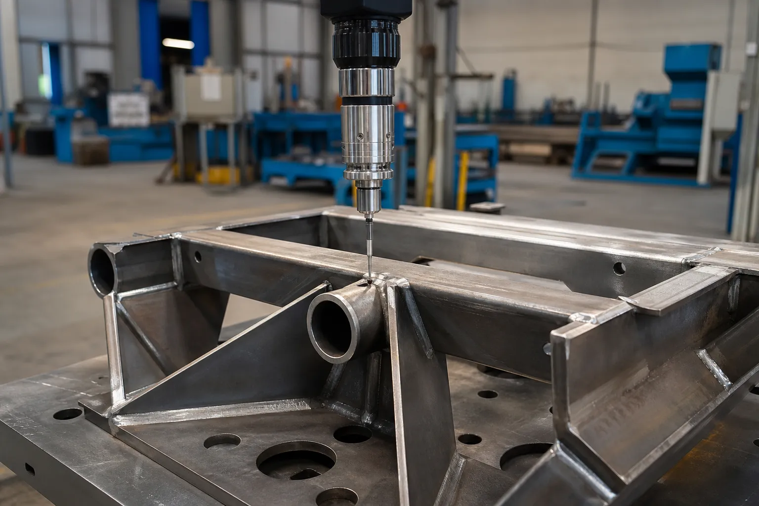
*Suunnittelukonseptin kuva. Se ei osoita validoitua korjaussekvenssiä, toimilaitesarja tai rakenneosan tulos.*
Älä käytä voimaa, toimilaitteiden määrä, syklin aika, suvaitsevaisuus, halkeamien havaitsemisnopeus tai yhteensopiva valutyyppi ilman projektin näyttöä. Näitä arvoja ei voi siirtää paperi- tai kilpailijajärjestelmästä.
Miksi suuret valukappaleet liikkuvat heiton jälkeen
Valetut rakenneosat vääristyvät, koska jähmettyminen ja jäähtyminen eivät ole koskaan tasaisia vaihtelevan paksuisen osan poikki. Paksut piirteet jäähtyvät hitaasti ja supistuvat myöhemmin kuin ohuet seinät, joten valu poistuu muotista tai muotista lukittuneen jäännösjännityskentän kanssa. Tämä jännityskenttä ei näy osalla - se ilmoittaa itsestään vasta myöhemmin, kun jokin muuttuu. Poisto, trimmaus, lämpökäsittely, räjäytystyöt, ja ennen kaikkea koneistus poistaa tai jakaa uudelleen rajoituksen, ja osa siirtyy kohti uutta tasapainoa. Takarakenteen valu, joka on mitattu hyväksyttäväksi valutilassa, voi ajautua pois asematoleranssista kriittisten rajapintojen koneistuksen jälkeen, koska materiaalin poistaminen yhdeltä pinnalta vapauttaa tasapainotusjännityksen toiselta puolelta.
Tästä syystä vääristymien hallinta rakennevaluissa on sekvenssiongelma, ei yhden painalluksen ongelma. Oikaisun ajoitus prosessireitin sisällä — ennen jännityksenpoistoa, karkean koneistuksen jälkeen, ennen koneistuksen lopettamista — muuttaa sekä kuinka paljon korjausta tarvitaan että kuinka vakaa korjaus pysyy. Jokaisella näistä reiteistä on erilainen riski: valetun osan korjaaminen voidaan peruuttaa myöhemmällä työstyksellä, viimeistellyn koneistetun osan korjaaminen voi vahingoittaa toiminnallisia pintoja. Reittipäätöksen tekee vastaava prosessiinsinööri, osan vääristymishistorian kanssa.
Mikä tekee korjauksen “3D” Planarin sijaan
Perinteinen tangon ja akselin oikaisu korjaa keskilinjan, joka on, ensimmäiseen tilaukseen, tasokäyrä: keula yhdessä tasossa, joskus keula mitattuna kahdessa kohtisuorassa tasossa ja yhdistettynä. Kone löytää mutkan korkeimman kohdan, tukee osaa kahdella alasimella, ja painaa huipulla. Ohjattava geometria on yksi neutraali akseli. Tämä on malli takana miten automaattinen akselin oikaisu toimii, ja se olettaa jäykkää, yhtenäinen osa.
Ohutseinämäinen rakennevalu murtaa nämä oletukset. Osuus ei ole yhtenäinen - kiskot, kylkiluut, ulokkeet ja ikkuna-aukot antavat sille suunnasta riippuvaa jäykkyyttä, joten sama kohdistettu voima tuottaa erilaisen taipuman riippuen siitä, missä ja mihin suuntaan se vaikuttaa. Poikkeama ei ole yksi mutka: se on jousen yhdistelmä yhdellä akselilla, lakaista sisään toinen, kiertää pituusakselin ympäri, ja yksittäisten toiminnallisten liitäntöjen paikallinen siirto – korkealla toisessa päässä oleva asennusalusta, porausakseli, joka on kallistettu suhteessa peruspistejärjestelmään. Mittaussuure on kunkin toiminnallisen rajapinnan sijainti ja suunta osakoordinaattijärjestelmässä, ei yhtäkään lopputulosta. Kaikki korjaussuunnitelmat, jotka jahtaavat vain yleiskeulaa, siirtävät rajapintoja, joita se ei aikonut siirtää.
Käytännössä, tämä tarkoittaa, että rakenteellisen valun virhekartta on rajapintapoikkeamien taulukko, ei ole keskilinjan napakaavio. Se tarkoittaa myös, että korjaustavoitteet on priorisoitava: rajapinnat, joissa on tiukat sijaintitoleranssit ja paritteluseuraukset, ovat etusijalla, ja toissijaisen geometrian annetaan kellua omien toleranssikaistansa sisällä. Tämä priorisointi on piirustuspohjainen suunnittelupäätös, joka tehdään ennen kuin puristusiskua suunnitellaan.
Päivämäärä ja kiinnitysstrategia tulee ennen korjausta
Valukappaleen mittaus ja korjaus ovat vain yhtä hyviä kuin peruspistejärjestelmä, johon ne viittaavat. Valupinnat ovat vetokulmia ja pintaa – ne eivät ole toistettavia eivätkä edustavia. Kappaleen on sijaittava piirustuksessa määritellyillä koneistetuilla peruspisteillä, samat ominaisuudet, joita asiakasmittari käyttää hyväksyessään. Jos mittaus käyttää yhtä ominaisuusjoukkoa ja asiakasmittari käyttää toista, nämä kaksi järjestelmää ovat eri mieltä pelkän asennusvirheen vuoksi, ennen kuin todellisen osan muunnelma tulee. Periaatteet ovat samat kuin käsitellyt porrastetun akselin mittauspisteen valinta, sovelletaan paljon vähemmän symmetriseen työkappaleeseen.
Ohutseinämäisten valujen kiinnittimet aiheuttavat lisätaakkaa: kiinnitys- ja tukikaavio ei saa kuormittaa osaa väärään muotoon. Vääristä kohdista tuettu valukappale taipuu oman painonsa ja puristusvoiman alaisena, ja mittausjärjestelmä tallentaa uskollisesti tuon taipuman osavirheeksi. Tuet kuuluvat jäykkien osien alle - kylkiluihin, kiskot, pomoklusterit - ei ikkuna-aukkojen keskellä. Jokainen valaisinkonsepti tulee todistaa uudelleen asettamalla: mitata, purkaa, lataa uudelleen, mittaa uudelleen, ja käsittele näiden lukemien välistä eroa pohjana sille, mitä järjestelmä voi ratkaista. Jos uudelleenasetuksen toistettavuus on huono, mikään alavirran korjaustarkkuus ei sulje silmukkaa, oppitunti, joka myös ajaa gage R&R harjoitus suoristaa linjoja.
Korjauskäsitteet ja niiden rajat
Valukappaleen korjaamisen mekaaninen idea on valikoiva paikallinen plastinen muodonmuutos: käytä voimaa valituissa kohdissa lyhentääksesi rakenteen toista sivua tai muuttaaksesi sen jäykkyystasapainoa, joten vapautunut osa asettuu lähemmäksi nimellisarvoa. On olemassa kaksi käsiteperhettä. Pistepuristus – sama perhe kuin kuvattiin point-press-oikaisu — Keskittää muodonmuutoksen tuki- ja puristuskohtaan ja soveltuu parhaiten jäykkien osien paikallisiin poikkeamiin. Hajautetut tai usean pisteen menetelmät jakavat pienemmät korjaukset useisiin paikkoihin, jotta ne muodostavat uudelleen pidemmän ajanjakson. Se, mikä konsepti sopii tiettyyn valukappaleeseen, riippuu siitä, missä poikkeamat sijaitsevat ja kuinka jäykkyys vaihtelee niiden välillä, Juuri tästä syystä yleinen painospesifikaatio ei vastaa mitään.
Kolme rajaa rajoittaa minkä tahansa korjausreitin. Ensimmäinen, valetulla alumiinilla on rajallinen sitkeys verrattuna vetotankoon, ja ohutseinämäinen osa tiivistää jännityksen: halkeamien riskien tarkastelu – missä halkeamat ovat todennäköisiä, miten niitä etsitään, ja kuka hyväksyy tuloksen - on ratkaistava ennen ensimmäistä koeiskua, ei sen jälkeen, kun epäilyttävä osa ilmestyy. Toinen, korjaus on vuorovaikutuksessa jäännösjännityskentän kanssa, joka aiheutti vääristymän. Tätä kenttää huomioimatta tehty korjaus voi rentoutua myöhemmän käsittelyn aikana, koneistus tai lämpöaltistus; stressikäyttäytyminen korjauksen jälkeen on aihe, jota käsitellään erikseen suoristus lämpökäsittelyn jälkeen. Kolmanneksi, Valukappaleen ylikorjausta ei yleensä saada takaisin painamalla, koska peruutuskuormitus kerää lohkoon matalan syklin väsymisvaurioita.
Kaikkia kolmea rajaa hallitseva kurinalaisuus on sama inkrementaalinen silmukka, jota käytetään tarkkuusakseleissa: pieni korjaus, vapauttaa, mittaa uudelleen, päättää. Mittaa–oikea–vapauta–mitta uudelleen -jakso, joka on kuvattu kohteelle pitkiä rakenneosia, kuten hissin ohjauskiskoja skaalaus periaatteessa valuihin, mutta yhdellä lisäsäännöllä: koska kohteena ovat rajapinnat yhden keskilinjan sijaan, jokaisen silmukan on luettava liitäntätaulukko uudelleen, ei vain huonoin yksittäinen lukema.
Mittaus, Eheyden ja vapauttamisen on oltava samaa mieltä
Kehitystietueen tulee säilyttää saapuvan geometrian muoto, datan/kiinnikkeen asetukset, mittausmenetelmä/tietoversio, korjausjärjestys, vapautettu geometria, pinta-/tarkastuslöydökset ja sijoitus. Jos eheystarkastus vaaditaan, sen menetelmä, Vastuullisten suunnittelu- ja laatutiimien on määriteltävä laajuus ja hyväksyntävaltuudet.
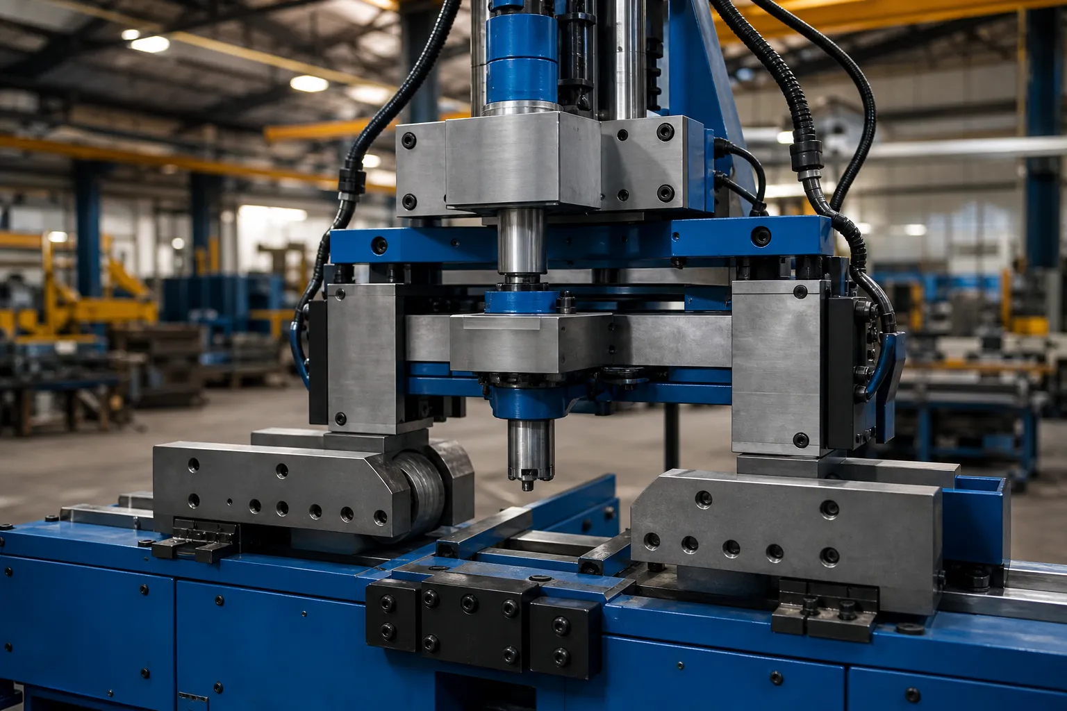
*Suunnittelukonseptin kuva. Se ei ole todiste käytettävissä olevista laitteista, turvasuunnittelu tai giga-valusovellus.*
Katso kiinnittimen toistettavuus ja peruspisteen istuvuus ja mittausepävarmuus suoruustarkastuksessa asiaankuuluvia valvontalaitteita varten; kumpikaan ei tarjoa näyttöä 3D-valukyvystä.
Todisteet vaaditaan ennen toimittajan vaatimuksia
AVOIN julkaisupäätös edellyttää todellista valtuutettua valuprojektia, piirustuksen määrittämä 3D-datumi ja kiinnike, mittaustiedot ennen/jälkeen/julkaisua, korjauskirjat, pinnan/eheyden tarkistus, hyväksytyt näytteet ja asiakkaan lupa. Siihen asti tämä sivu on tutkimuskehys. Laajaan tekniseen keskusteluun, ota yhteyttä StraighteningTechiin valtuutetuilla projektitiedoilla.
Vaadittava vahvistus ennen järjestelmävaatimusta
Kaikki giga-valukorjauksen järjestelmävaatimukset tarvitsevat määritellyn työkappaleen laajuuden, kalibroidut peruspisteet ja kiinnikkeet, jäljitettävät mittaustiedot, ja korrelaatio asiakkaan oman mittarin kanssa. Yleinen koneominaisuus ei ole vahvistettu tulos tälle aiheelle.
FAQ
Voidaanko gigavalettu rakenneosa oikaista tangonoikaisukoneella?
Ei sisääntulona. Tangon oikaisukoneet olettavat tasaisen jäykän osan ja yhden keskiviivavirheen. Ohutseinämäisellä rakennevalulla on suunnasta riippuvainen jäykkyys, kierre ja rajapinnan sijainnin poikkeamat, ja tarvitsee datamin, kiinnitys- ja mittauskonsepti, joka on rakennettu sen piirustuksen ympärille – sekä valun sitkeyteen sopiva halkeamisriskin arviointi. Osa taustalla olevasta korjausfysiikasta on jaettu; työtila, mittaus ja validointi eivät ole.
Pitäisikö stressin lievitys tulla ennen tai jälkeen oikaisun?
Se riippuu vääristymähistoriasta ja prosessireitistä, ja se on vastuullisen prosessi-insinöörin päätös. Korjaus ennen stressin lievitystä vaarantaa korjauksen myöhemmin rentoutumisen; korjaaminen jälkeen poistaa yhden epävakauden lähteen, mutta saattaa kohdata kovemman materiaalin. Se, mistä ei pitäisi neuvotella, on se, että valinta on tietoinen, dokumentoitu, ja johdonmukaisuus kokeen ja tuotannon välillä.
Mitä todisteita ostajan tulee pyytää ennen 3D-oikaisuehdotuksen hyväksymistä??
Piirustuksen määrittelemä 3D-datumin ja kiinnityskonsepti, mittaustiedot vastaanotettuina ja vapautettuina, jokaisen kokeen osan korjaustietue, laatutiimin kanssa sovittu eheys tai halkeamien tarkastus, ja hyväksyntä asiakasmittarin mukaan. Ehdotus, joka sisältää vain koneen tekniset tiedot, ilman niitä esineitä, ei ole ehdotus tälle työlle.
Aiheeseen liittyvät StraighteningTech-resurssit
Katso miten automaattinen akselin oikaisu toimii, suoristusnäytteen testaus ja hyväksyminen ja akselin suoruus vs juoksu vs TIR yleisiin ohjausrajoihin, jotka ovat voimassa ennen kykyvaatimusta 3D Giga-Cast-rakenneosien oikaisu.

*Suunnittelukonseptin kuva.*
Giga-casting-korjaus on automaation ensimmäinen keskustelu – the manuaalinen ja automaattinen vertailu käsittelee prosessihypyä, ja ROI-kotelo automaattiseen suoristukseen käsittelee pääomakysymyksen.