
Keevitatud konstruktsioon ei ole ühtlane võll, latt või tala. See võib kombineerida kasti sektsioone, taldrikud, torud, risttalad, kiilud, ülemused, kinnituspadjad, augud ja kronsteinid ühes kolmemõõtmelises koosluses. Keevitamise kokkutõmbumine, järjestus, vaoshoitus, lõikamine, käsitsemine ja stressi leevendamine võivad korraga liigutada mitmeid funktsionaalseid omadusi.
Usaldusväärne keeviskonstruktsioonide õgvenduspress peab seetõttu kontrollima kogu koormusteed, mitte lihtsalt lükata kõrgeimat nähtavat punkti. Lahendus peab enne masina valimist vastama viiele küsimusele:
- Millised funktsionaalsed nullpunktid ja liidesed määravad vastuvõetava koostu?
- Kas viga on globaalne vibu, väänata, nurga moonutus, lokaalne paneeli paindumine, augu/ülaosa nihkumine või kinnitusviga?
- Kus võib toetada, reaktsiooniplokid ja hüdraulikapead puutuvad kokku õhukesi paneele kahjustamata, keevitada varbad, töödeldud padjad või augud?
- Kas toorik võib jääda paigale, kui pukk või paranduspead liiguvad igasse punkti?
- Kuidas koormamata koostu ümber mõõdetakse, keevisõmblus kontrollitakse ja vabastatakse pärast iga parandusseeriat?
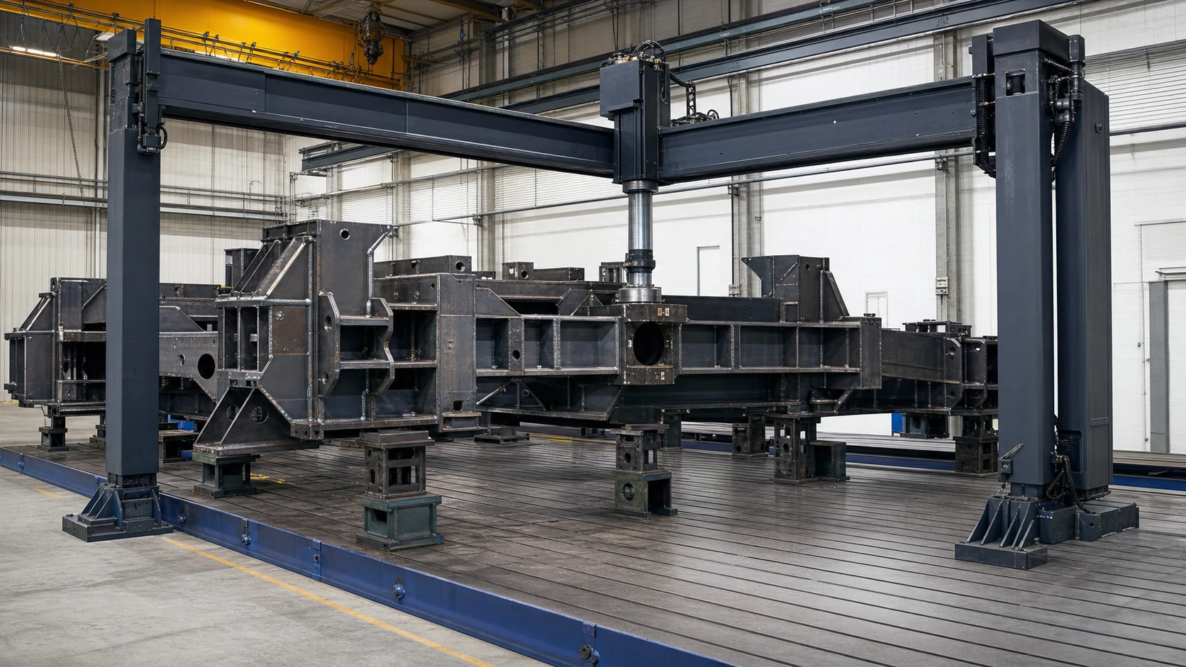
*Tehnilise kontseptsiooni illustratsioon suurest keevisõmblusest laia voodiga liikuva portaaliga õgvenduspressil. See ei ole kliendi saidi foto ega toimivusnõue. Tegelik voodi suurus, toetab, paranduspead, jõu- ja vastuvõtupiirid nõuavad kontrollitud valmistamist ja representatiivse näidise katseid.*
Enne pressi kujundamist määrake tootmisperekond
| Töödeldavate detailide perekond | Tüüpilised omadused | Peamine sirgendamise väljakutse |
|---|---|---|
| Masina raam või alus | Kasti sektsioonid, mehaaniliselt töödeldud kinnituspadjad, rööpad ja ülemused | Globaalne keerdumine pluss funktsionaalsete liideste samatasandilisus |
| Keevitatud šassii või alamraam | Pikad rööpad, risttalad, sulgudes ja vedrustuse liidesed | Diagonaalne suhe, lokaalne sõlme liikumine ja mitmeteljeline moonutus |
| Rasketehnika keevitamine | Paksud plaadid, valatud/sepistatud sisetükid, kiilud ja pöördeavad | Suured reaktsioonikoormused ja puuri ja padja joondamine |
| Kast või korpuse raam | Kohaliku tugevdusega õhukesed paneelid ja ukse/tihendi liidesed | Kohalik paindumine ja kättesaamatud reaktsioonipunktid |
| Keevitatud tugi- või kronsteini koost | Mitu plaati, augud ja kinnituspinnad | Nurgamoonutus ja augumustri asend |
| Suur struktuurne valmistamine | Pikad avatud sektsioonid ja ühendusplaadid | Käitlemine, longus ja globaalne 3D geomeetria |
| Hapnikkütusega või plasma lõigatud valmistatud kuju | Lõikeplaadi moonutus pluss hilisem keevisõmbluse kokkutõmbumine | Eraldage plaadi tasapinnalisus koostu joondamisest |
| Järeltöötlus keevitus | Valmis padjad, puurid ja pinnad | Funktsionaalne pinnakaitse ja piiratud korrektsiooniaken |
See leht hõlmab kolmemõõtmeliste keevissõlmede kontrollitud korrigeerimist töökojas. Kasutage I/H-tala ääriku moonutamiseks spetsiaalset talalahendust, plaadiprotsess tasapinna tasandamiseks, ja pöörlevate komponentide võlliprotsess. Autode põrkeraami remont ja koormatud konstruktsioonide välikorrektsioon on väljaspool seda tootmistöövoogu.
Külmutage tootmisetapp
Pärast nakkekeevitamist
Koostu võib siiski olla ehitusseadmes ja see ei pruugi esindada selle vabastatud geomeetriat. Mõõtmist vaoshoitud seadmes ei saa käsitleda lõpliku vabaoleku aktsepteerimisena. Varajane korrigeerimine võib aidata keevitusjärjestust, kuid hilisemad keevisõmblused võivad moonutusi uuesti tekitada.
Pärast täielikku keevitamist
Keevisõmbluse jada ja piiramine on lõppenud, kuid struktuur võib siiski vajada jahutamist, puhastamine ja ülevaatus. Paranduskõlblikkus sõltub keevisõmbluse olekust, materjalist, paksuse üleminekud ja heakskiidetud tootmisprotseduur.
Pärast stressi leevendamist või kuumtöötlust
Termiline töötlemine võib muuta geomeetriat ja materjali reaktsiooni. Enne stressi leevendamist välja töötatud retsepti ei tohi ilma uuesti kinnitamata üle kanda.
Enne töötlemist
Kui varu jääb funktsionaalsetele padjanditele või avadele, sirgendamine võib taastada töötlemisvaru ja vähendada allavoolu seadistusviga. Protsess peab kasutama sama funktsionaalse nullpunkti strateegiat, mis on kavandatud töötlemiseks.
Pärast töötlemist või katmist
Valmis puurid, padjad, juhtpinnad, värvimine ja galvaniseerimine muutuvad kaitstud funktsioonideks. Parandusaken on kitsam, ning protsessijärgne mõõtmete ja pinna kontroll muutub kohustuslikuks.
Ehitage funktsionaalne 3D nullpunkti ahel
Sirgendamise sihtmärk peaks tulema joonistamise ja kokkupanemise funktsioonist, mitte sellelt pinnalt, millelt on joonlauaga kõige lihtsam ligi pääseda.
Mõõtmiskava peaks määratlema:
- esmane, sekundaarsed ja tertsiaarsed andmed;
- paigaldusaluse tasapinnalisus ja tasapinnalisus;
- puuri või ülaosa teljed ja keskpunktide kaugused;
- augu-mustri asend ja diagonaalsuhe;
- raami vibu, keerd ja risttala ruudukujulisus;
- liidese kõrgus, paralleelsus ja nurksuhe;
- tugipunktide positsioonid, kontaktjõud ja vaoshoitav olek;
- keelutsoonid keevisarmatuuri ümber, pritsmed ja karedad leegiga lõigatud servad;
- temperatuuri, jahutus- ja stabiliseerimisseisund;
- korratavus pärast mahalaadimist, pöörlemine ja uuesti kinnitamine;
- correlation with the customer's CMM, laserjälgija, seade või funktsionaalne mõõtur.
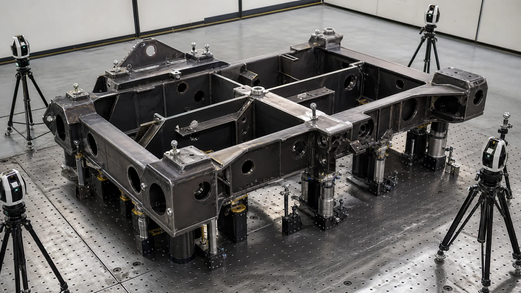
*Insenerikontseptsiooni illustratsioon keevisõmbluse kohta, mida mõõdetakse kontrollitud tugipunktide tugede ja funktsionaalsete sihtmärkide abil. See ei ole ette nähtud anduri paigutus. Tegelikud sihtkohad, koordinaatide süsteemi ja aktsepteerimisarvutuste jaoks on vaja joonise ja kliendi gabariidi korrelatsiooni.*
Eraldage moonutus kahjustustest ja kinnitusvigadest
| Täheldatud signaal | Võimalik põhjus | Nõutav marsruut |
|---|---|---|
| Sileda raami vibu korratakse pärast vabastamist ja uuesti laadimist | Globaalne keevisõmbluse kokkutõmbumine või vormimismoonutus | Kandidaat kontrollitud pika pikkusega korrektsioonile |
| Vastasnurgad liiguvad erinevates Z-suundades | Globaalne keerdumine või diagonaalne moonutus | Mitmepunktiline 3D mõõtmine ja väändeteadlik korrektsioon |
| Kui põhiraam on stabiilne, nihutatakse üks kronstein või ülaosa | Lokaalne soojussisend, järjestuse või kinnituse piiramine | Kohaliku sõlme korrigeerimine kontrollitud reaktsiooniteega |
| Õhuke paneel näitab laineid jäikuse vahel | Kohalik paindumine või õlikonserveerimine | Paneelispetsiifiline insenerimarsruut; ärge rakendage üldist punktkoormust |
| Geomeetria muutub, kui klambrid või toed liiguvad | Armatuuri piiramine, ebastabiilne tugi või raske osa longus | Külmutage nullpunkti tingimus ja korrake mõõtmist |
| Lugemine muutub pärast pritsmete või katte eemaldamist | Pinna saastumine või vale sihtmärk | Puhastage ja kvalifitseerige mõõtepind |
| Moonutused langevad kokku praguga, alla lõigatud, sulandumise puudumine või rebenenud materjal | Keevisõmbluse või mitteväärismetalli defekt | Ülevaatus ja parandusdispositsioon enne sirgendamist |
| Paigalduspadjad on tasapinnalised, kuid avamuster on vale | Valmistamine, töötluse või funktsiooni asukoha viga | Funktsioonispetsiifiline paigutus; ülemaailmne surve võib seda hullemaks muuta |
Sirgendamine muudab geomeetriat. See ei paranda vastuvõetamatut keevisõmblust, pragu, lamineerimine, rebenenud auk, puuduv osa või heakskiitmata termilised kahjustused.
Kontrollige keevisõmblusi enne parandusjõu rakendamist
Sissetulev värav peaks kinnitama:
- materjalide ja keevitusprotseduuride jälgitavus;
- keevitamine, jahutamise ja stressi leevendamise staatus;
- visuaalse kontrolli paigutus;
- kriitiliste keevisõmbluste jaoks nõutav mittepurustava kontrolli olek;
- teadaolevad remondikohad ja eelnev paranduste ajalugu;
- pragu, alla lõigatud, poorsus, sulandumise puudumine või muu asjakohane näidustuse paigutus;
- viimistletud pinnad, katted ja omadused, mis peavad jääma kaitstuks;
- kavandatava mehaanilise korrigeerimise etapi insenerikinnitus.
Täpne kontrollimeetod ja vastuvõtuväärtused kuuluvad kehtivale joonisele, keevituskood ja kliendi kvaliteediplaan. Rohelise geomeetriaga tulemus ei saa alistada vastuvõetamatut keevisõmbluse või mitteväärismetalli seisundit.
Kujundage tugi- ja reaktsioonikaart
Iga pressimisjõud vajab täielikku teed läbi töödeldava detaili ja masina aluspinnani. Kaart peaks tuvastama:
Vaikimisi kaitstud või ülevaatustsoonid
- toetamata õhukesed plaadid või paneelid;
- keevitada varbad, käivitub/seiskub ja kontrollimata keevisõmblusnäidud;
- mehaaniliselt töödeldud kinnituspadjad, juhtpinnad ja tihenduspinnad;
- puurid, augud, niidid ja asukoha määramise funktsioonid;
- teravad lõikude üleminekud ja vabad plaadiservad;
- identifitseerimis- ja jälgitavusmärgid;
- pinnakatted ja arhitektuursed pinnad;
- mõranenud, rebenenud, tugevalt korrodeerunud või varem remonditud tsoonid.
Potentsiaalselt heakskiidetud koormustsoonid
- tugevdatud sõlmed, kus risttalad, kiilud ja suletud sektsioonid kannavad üle jõudu;
- laiad struktuursed maad, mida toetatakse kohaliku paindumise vastu;
- vahetatavad kontaktpadjad, mis sobivad tegeliku pinnaga ja lubatud märgistusega;
- ajutised tööriistaliidesed, mis sisalduvad juhitava protsessi disainis;
- reaktsioonipunktid on kontrollitud ülevaate joonistamisega, proovide testimine ja, kui nõutakse, insenerianalüüs.
Reaktsiooniplokid peavad olema kolmemõõtmeliselt reguleeritavad, ilma et need muutuksid kontrollimatuteks kõvadeks punktideks. Ühe raami revisjoni jaoks töötav tugi võib augu alla kukkuda, keevitada varvas või õhuke paneel teisele.
Valige geomeetriast ja käitlemisest pressiarhitektuur
Laia voodiga reisiv pukkpress
Savage Engineering kirjeldab avalikult kolmeteljelise silindri liikumisega laiapõhjalisi keevituspresse, nii et suured toorikud võivad paigal püsida, kuni silinder soovitud asukohta liigub. Hidrogarne kirjeldab sarnaselt liigutatavat portaali ja külgsuunas liikuvat pead, et pääseda erinevatele paranduspunktidele ilma konstruktsiooni korduvalt liigutamata.
See arhitektuur võib sobida suurtele, rasked või ebamugavad keevisõmblused, kui:
- kogu osa ja selle toed mahuvad jäigale võrdlusalusele;
- pukk ja pea võivad jõuda kõigi heakskiidetud parandussõlmedeni;
- hüdraulilised töötõstukid või tugisüsteemid asetavad reaktsiooniplokid ohutult;
- juhtseade piirab silindri asendit, jõudu, nihe ja iteratsioon;
- vabastatud geomeetriat mõõdetakse pärast aktiivse paranduskoormuse eemaldamist.
C-Frame või Multi-Action Press
Beckwood kirjeldab C-raami süsteeme, millel on mitu sõltumatult juhitavat toimingut suurte keevisõmbluste ja valmistatud sõlmede jaoks. See lähenemisviis sobib lokaalsete moonutuste korral, kus tuleb koordineerida mitut reaktsiooni- ja parandussuunda ning vaja on avatud juurdepääsu.
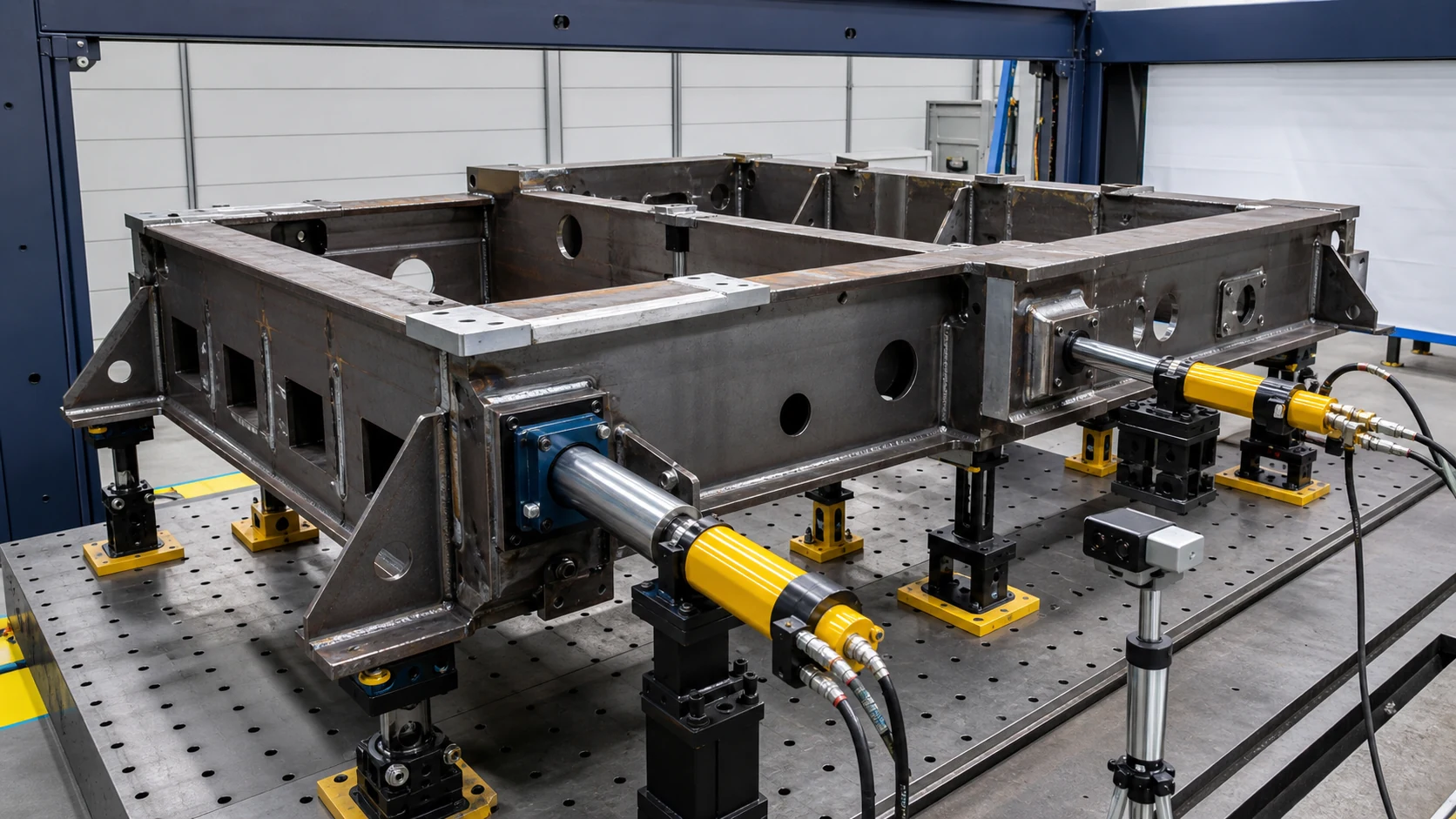
*Tehnilise kontseptsiooni illustratsioon sõltumatult paigutatud paranduspeadest ja tugevdatud sõlmede kaudu mõjutavatest reaktsioonitugedest. See ei ole universaalne seade. Laadimisteed, kohalik stress, keevisõmbluse seisukord, toe jäikus ja tagasitõuge nõuavad tehnilist ülevaatust ja näidise valideerimist.*
Horisontaalne buldooseri stiilis press
Külgtoimega horisontaalpress võib pikkade raamide laadimist lihtsustada, šassii osad ja konstruktsioonikomponendid. See nõuab siiski stabiilset külgmist tõket ja kontrollitud tsentrivälist koormusteed.
Kuumuse sirgendamine
Kuumsirgendamine on eraldi kontrollitud protseduur materjaliga, keevitada, temperatuuri ja kvalifikatsiooni nõuded. Sellel lehel ei käsitleta põleti kontrollimatut kuumutamist mõõdetud mehaanilise korrigeerimise asendajana.
Lugege presssirgendamine vs rullsirgendamine üldise meetodi võrdluse jaoks. Keerulised keevisõmblused nõuavad tavaliselt punkt- või mitmetoimelist korrektsiooni, mitte üldist läbiva etteanderulli retsepti.
Kasutage vabastatud osa suletud ahelat
- Tehke kindlaks valmistamise perekond, joonise läbivaatamise ja valmistamise etapp.
- Kinnitage keevisõmbluse kontrolli ja korrigeerimise sobivust.
- Puhastage töödeldav detail ja kaitske funktsionaalseid liideseid.
- Laadige see juhitavale tugipunktile ja tugiseadmele.
- Mõõtke kogu 3D geomeetria ja klassifitseerige iga veakomponent.
- Valige kinnitatud tugi, reaktsiooni- ja paranduspunktid.
- Paigutage pukk või paranduspead nullpunkti asjatult liigutamata.
- Rakendage kontrollitud koormustee kaudu piiratud jõudu või nihkumist.
- Laadige parandusjõud täielikult maha ja stabiliseerige töödeldav detail.
- Mõõtke uuesti samad tunnused samas koordinaatsüsteemis.
- Korrake ainult jõu piires, nihe, lokaalse deformatsiooni ja iteratsiooni piirid.
- Täielik nõutav keevisõmblus, pinna ja funktsionaalsete liideste kontrollid.
- Salvesta sissetulevad, vahe- ja lõppgeomeetria koos koostu identiteediga.
Juhtseade peaks takistama OK mõõtmega detaili automaatset vabastamist NOK keevisõmblusega, kahjustatud pind või ületatud protsessi piirmäär.
Raskete osade käsitsemise ja ohutuse insener
Suured keevisõmblused tekitavad riske väljaspool pressimistonnaaži. Rakk võib vajada:
- kraana või ülekandekäru laadimine määratletud tõstepunktidega;
- hüdraulilised töötõstukid tugede ja reaktsiooniplokkide positsioneerimiseks;
- statsionaarsete osade arhitektuur, et vähendada kraana korduvaid liikumisi;
- raskuskeskme ja stabiilsuse kontroll igale perele;
- blokeeringud pukkliikumise ümber, pea liikumine ja rippuvad koormused;
- ohutu juurdepääs kontrollimiseks ja tööriistade vahetamiseks;
- kaitstud voolikud, kaablid ja andurid väljaspool koormusteed;
- retsepti kinnitus detaili orientatsiooni ja joonise revisjoni kohta;
- kontrollitud taastumine pärast peatatud või mittetäielikku korrektsioonitsüklit.
Masina võimsus tuleks valida halvima kinnitatud koormusjuhtumi hulgast, sealhulgas väljaspool keskpunkti laadimine ja voodikate, mitte ühestki nominaaltonnaažinumbrist.
Tehnilise ettepaneku jaoks vajalik teave
| Sisend | Minimaalne detail |
|---|---|
| Töödeldava detaili määratlus | Montaaži joonis, läbivaatamine, üldine ümbrik, mass ja raskuskese |
| Materjalid | Hinded, paksused, kuumtöötlus ja erinevatest materjalidest vuugid |
| Keevitamise protsess | Järjestus, menetlust, kontrolli olek, remondi ajalugu ja stressi leevendamine |
| Funktsionaalsed nullpunktid | Paigalduspadjad, puurid, ülemused, augud ja liidese hierarhia |
| Veakaart | Sissetulevad 3D-mõõtmised, vibu, väänata, nurk- ja lokaalne deformatsioon |
| Kaitstud omadused | Õhukesed paneelid, keevisõmblused, töödeldud pinnad, augud, niidid ja katted |
| Nõutav tulemus | Joonistamise tolerants, koordinaatsüsteem, nullpunkti piiramise ja gabariidi meetod |
| Laadi juurdepääs | Heakskiidetud parandus- ja reaktsioonitsoonid pluss keelatud kontaktalad |
| Käitlemine | Laadimismeetod, tõstepunktid, orientatsiooni, rotatsiooni ja rajatiste piirangud |
| Tootmisvajadus | Toodete segu, lüüa sihtmärki, üleminek, automatiseerimine ja jälgitavus |
| Valideerimine | Proovi kogus, halvimal juhul perekonnad, mõõtekorrelatsioon, FAT/SAT ja aruandevorming |
Kui need sisendid on puudulikud, õige esimene tulemus on mõõtmine, tugi- ja proovikatseplaan – mitte väljamõeldud tonnaaž, täpsus või tsükli aeg.
Proovitestist kuni tootmise vabastamiseni
- Vaadake joonised üle, keevisõmblusdokumendid ja kvaliteedinõuded.
- Looge geomeetria jaoks peremaatriks, mass, nullpunktid ja kaitstud funktsioonid.
- Külmutage 3D-mõõtmise koordinaatide süsteem ja tugitingimus.
- Kontrollige esinduslikke tavalisi ja halvima juhu proove.
- Modelleerige või vaadake üle pakutud koormus ja reaktsiooniteed.
- Prooviga piiratud korrektsioon heakskiidetud proovidel.
- Kvantifitseerige tagasiminek, teljeülene liikumine, lokaalne deformatsioon ja korratavus.
- Kontrollige keevisõmblusi uuesti, pinnad ja funktsionaalsed liidesed.
- Correlate released results with the customer's CMM, jälgija või funktsionaalne kinnitus.
- Tööriistade külmutamine, retseptid, piirid, ohutusloogika ja jälgitavuse väljad.
- Jookse näidiskatse ja vastuvõtmine enne kinnitatud perekonna vabastamist.
Saada meile oma keevitusjoonis, 3D ülevaatusakt, keevisõmbluse olek ja kaitstud funktsioonide kaart sirgendamise ja käsitsemise kontseptsiooni saamiseks. StraighteningTech arendab pressi arhitektuuri, tugitööriistad, mõõtmise ja kontrollimise töövoog ümber tegeliku valmistamise, mitte rakendada üldist pressi seadistust.