
Una traza de indicador giratorio puede contener varios efectos a la vez. Puede reflejar el eje de la pieza de trabajo., redondez local, forma cilíndrica, una relación de datos, asiento de apoyo, error de fijación, configuración de la sonda o una función interrumpida. Llamar “doblado” a cada lectura alta puede llevar a una acción de corrección incorrecta y puede dañar una pieza que realmente necesita una medición o revisión de mecanizado..
Esta guía explica cómo diagnosticar la señal antes de tomar una decisión de enderezamiento.. No establece un sistema de medición de StraighteningTech, tolerancia, resolución del sensor, procedimiento de referencia o capacidad de corrección. El dibujo controlado y el método de inspección del cliente son necesarios para las decisiones finales..

*Ilustración del concepto de ingeniería. Muestra que una señal giratoria puede incluir variación de forma.; no es un resultado de medición para una pieza del cliente ni una configuración de inspección prescrita.*
Nombra la característica antes de leer el indicador.
La redondez describe una condición de forma de sección transversal.. La curvatura del eje describe la trayectoria espacial de un eje de referencia.. El descentramiento es una medida rotativa relativa a una configuración de referencia y puede incluir múltiples contribuyentes.. Coaxialidad, La concentricidad y la cilindricidad también tienen definiciones y requisitos de inspección distintos.. El dibujo debe identificar qué característica controla la aceptación..
| Señal o característica | Pregunta de diagnóstico |
|---|---|
| Redondez / lobulado | ¿Cambia el radio local a medida que gira la sección?? |
| curvatura del eje | ¿El eje de referencia cambia de posición a lo largo de la longitud?? |
| Sin | cual dato, Los soportes y la estación de sonda crean la lectura.? |
| relación coaxial | ¿Se comparan múltiples características con un eje común definido?? |
| señal del accesorio | ¿Reasentar o cambiar la orientación del soporte cambia el resultado?? |
Ver rectitud del eje, agotamiento y TIR y coaxialidad versus agotamiento para terminología relacionada.
What a Rotating Trace Is Made Of
A probe reading taken while a part rotates is, mathematically, a mix of components that repeat once, twice, three times and more per revolution. Reading the mix is the core diagnostic skill. A once-per-rev component means the surface is, on average, further from the rotation axis on one side than the other — which is the signature of either an axis offset between the part’s reference geometry and the rotation axis, or of a bent axis displacing the section as a whole. A twice- or three-times-per-rev component means the section is oval or lobed: the local radius itself changes around the circumference, a form condition of the cross-section that no amount of axis correction removes. Higher-frequency content usually reflects surface texture, keyways and interrupted features, or vibration entering through the supports.
The decisive separation between the two once-per-rev causes is axial. A true bend displaces different stations by different amounts and often in different directions, so the once-per-rev component’s amplitude and phase change as the probe moves along the part. A pure eccentricity condition — centers offset, seat offset, chuck runout — produces a once-per-rev component that keeps the same phase and proportional amplitude at every station. One trace at one station cannot distinguish them; a short axial map routinely can. That is the reasoning behind the multi-station discipline above, and behind multipoint measurement arrangements that read several stations in one setup.
Where Lobing Comes From
Lobing is rarely random — it carries the fingerprint of the machining that produced the surface, which is what makes it diagnostic. Three-lobe out-of-roundness is the classic signature of parts ground on centerless machines, where the part floats between wheel, regulating wheel and blade and the geometry locks into a three-point stability condition. Even-lobe ovality traces back to opposing clamping or distortion relieved after machining — a thin sleeve released from a chuck, a part that relaxed after heat treatment. Odd lobing beyond three appears with certain workholding arrangements and with relapsing of interrupted cuts. Knowing the part’s process route therefore tells you what lobing to expect and whether an observed lobe count is a workpiece reality or an artifact of the current setup: a lobe count that changes when the part is reseated in different orientations is being generated by the setup, not the part.
Inspeccione el dato y la configuración primero
Antes de interpretar la parte, verificar las características del centro, revistas u otras superficies de referencia, condición de soporte, limpieza, contacto de sonda, método de rotación y estación axial. Un centro dañado, rebaba, asiento sucio, El soporte incorrecto o el contacto de la sonda en una superficie interrumpida pueden crear una desviación aparente que no representa una curvatura del eje..
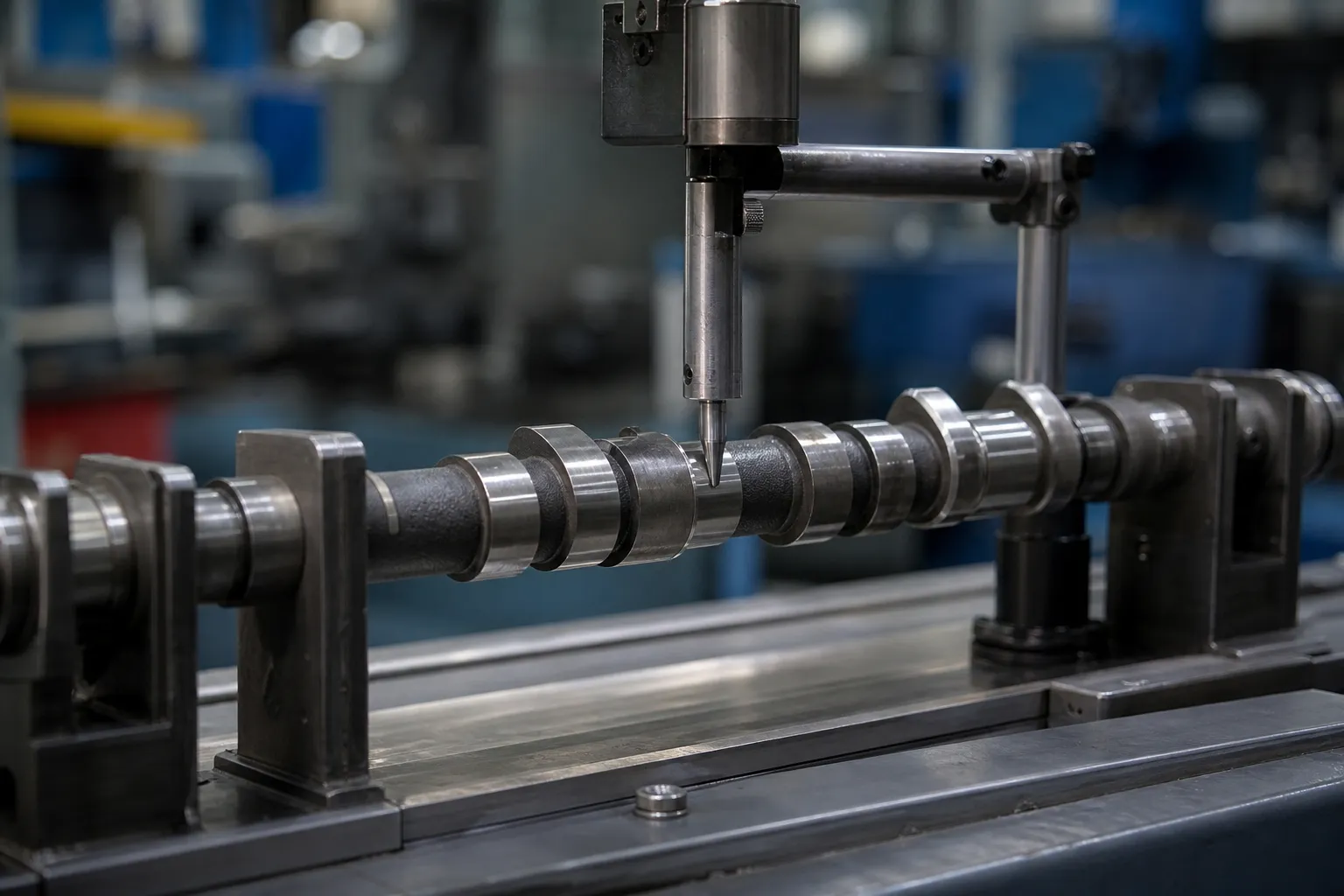
*Ilustración del concepto de ingeniería. Ilustra la medición del diario con reconocimiento de características.; datos reales, Las pistas de palpación y las máscaras angulares dependen de la pieza a controlar.*
Utilice una verificación de reinicio/repetición y compare múltiples estaciones. Si el seguimiento cambia sustancialmente después de repetir la configuración, Investigar la fijación o la realización del dato antes de aplicar la fuerza de corrección..
Comparar múltiples estaciones y orientaciones
La curvatura del eje generalmente requiere un mapa axial. Pueden aparecer redondez o lobulaciones locales en una estación pero no en otra. Una lectura única del indicador total en un momento dado no puede demostrar qué contribuyente domina. Grabar ubicaciones de estaciones, orientación, condición de referencia y la traza o resultado calculado requerido por el procedimiento de aceptación.
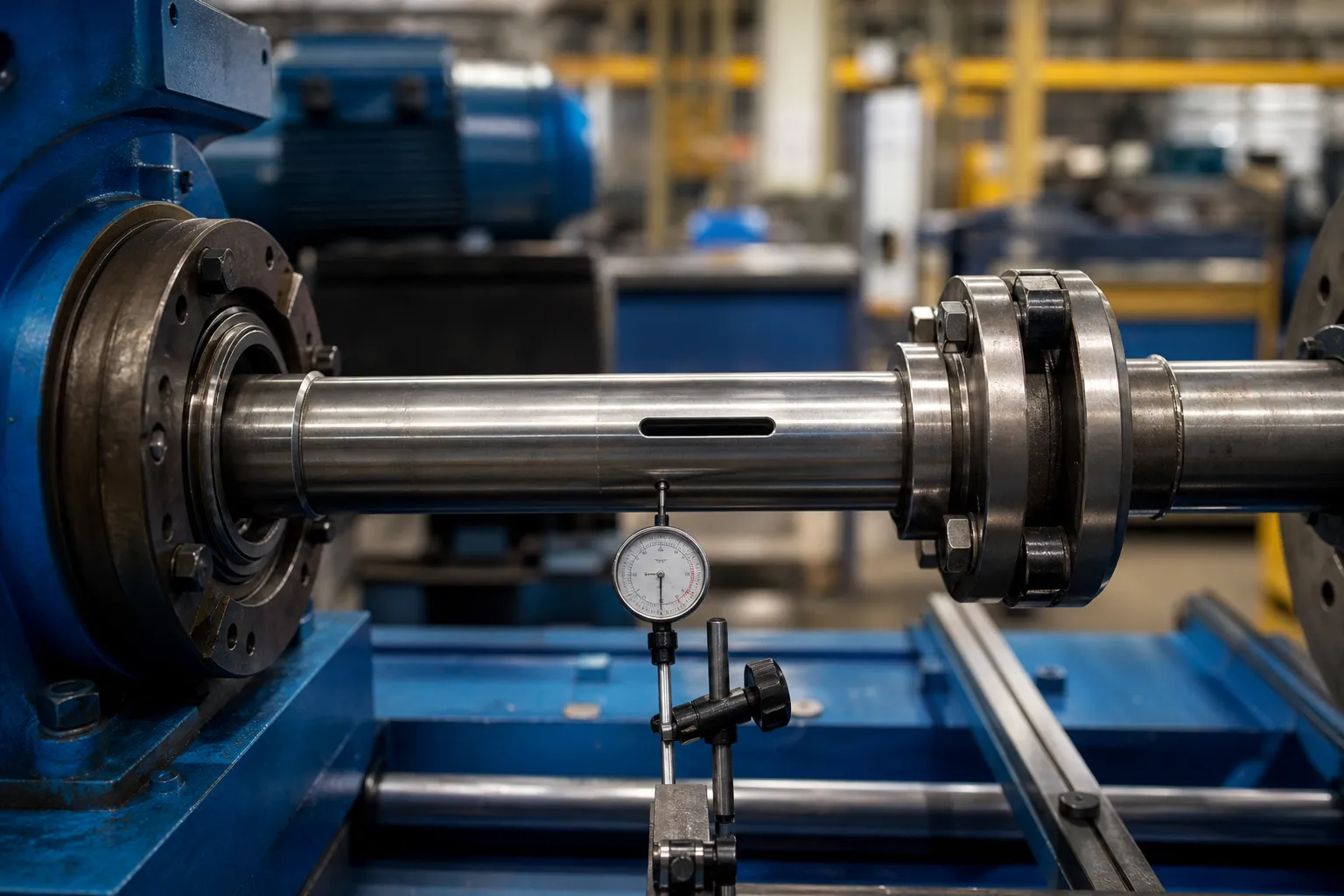
*Ilustración del concepto de ingeniería. Representa una pregunta de medición rotacional de múltiples funciones., no es un dispositivo aprobado o una conclusión de que la señal observada está distorsionada.*
Separating Spindle Error From Part Error
On any rotating instrument, the reading contains the part’s geometry plus the rotation error of the instrument itself — spindle runout, bearing wander, support eccentricity. Precision metrology has standard separation techniques for this, and their logic is worth knowing even when the full apparatus is not available. Reversal methods measure the part in one orientation, then rotate the part exactly half a revolution relative to the fixture and measure again: part error keeps its sign in part coordinates while setup error keeps its sign in machine coordinates, so combining the two traces separates them. Multistep methods extend the same idea through a series of indexed orientations. On a production straightening machine, the practical descendants are simpler: reseating the part in a different clocking orientation and checking whether the trace rotates with the part or stays fixed in the machine tells most of the story, and comparing readings before and after swapping a support identifies which element contributes what.
These checks cost minutes and prevent the most expensive mistake on this page: correcting a bend that lives in the bench. They also make the eventual correlation to the customer gauge meaningful, because both sides of that comparison are then measuring parts rather than setups — the premise underlying calibre R&R studies on straightening lines.
A Practical Diagnostic Sequence
The checks above assemble into a fixed order of operations that experienced lines follow before any correction decision. Primero, clean and inspect the seating features — centers, revistas, support vee blocks — for damage, burrs and debris, since the cheapest explanation is always the setup. Segundo, take a trace, reseat the part in the same orientation, and retrace: disagreement beyond the setup’s established repeatability stops the investigation at the fixture. Tercero, reseat in a rotated orientation: a trace that follows the part is a part signal; one that stays fixed in the machine is a machine or fixture signal. Fourth, map at least three stations along the length and note how the once-per-rev component’s amplitude and phase behave: varying amplitude and rotating phase indicate bend; constant phase with proportional amplitude indicates eccentricity. Fifth, look at the lobe content in relation to the part’s machining history before believing any form conclusion. Only then choose the response — correction for confirmed axis bend within approved zones, or the alternative routes for everything else, with the released-state condition treated per loaded versus released measurement.
The sequence exists because each step filters a class of false positives that would otherwise survive to the next. Skipping ahead to correction is how parts get pressed for eccentricity fixtures, ovality and chucking artifacts — damage that no later measurement undoes.
Seleccione la respuesta del diagnóstico
Si la evidencia respalda una condición de flexión del eje y hay zonas de contacto/soporte aprobadas, una ruta de enderezamiento candidata puede evaluarse mediante una prueba de muestra. Si la señal es principalmente redondez., geometría interrumpida, una cuestión de datos, error de fijación o una relación de característica separada, Es posible que se requiera un proceso diferente o una revisión de inspección.. No utilice el alisado para compensar un problema de medición..
Para corrección local controlada, ver alisado con prensa puntual. Para correlación con el método de inspección final, see machine gauge versus customer gauge correlation.
Validar con el medidor del cliente
El plan de muestra debe incluir condiciones conocidas/de referencia cuando estén disponibles., repetir la configuración, múltiples estaciones, medición del estado liberado, identificación de piezas y accesorios, retención de datos sin procesar y correlación del calibre del cliente. El resultado debe indicar qué característica se evaluó y qué incertidumbre o limitaciones de configuración permanecen.
Preguntas frecuentes
¿Un TIR alto siempre significa que el eje está doblado??
No. TIR puede incluir datos, redondez, accesorio y otros contribuyentes. Diagnostique primero la configuración y las múltiples estaciones.
¿Puede alisarse la redondez correcta??
No como conclusión general.. La redondez es una condición geométrica diferente y puede requerir un proceso o ruta de inspección diferente..
¿Por qué repetir la configuración??
Volver a leer después de volver a asentar ayuda a distinguir la señal de la pieza de trabajo del soporte, variación de referencia o accesorio.
What does a three-lobed trace usually indicate?
Most often, a surface produced by centerless grinding, where the three-point contact of wheel, regulating wheel and blade locks the section into a three-lobe form condition. It is a cross-sectional form issue, not an axis issue, and it should be verified against the part’s machining history before any response is chosen.
How can I tell eccentricity from bend with one probe?
Move the probe along the part and watch the once-per-rev component. Bend shows varying amplitude and shifting phase between stations; eccentricity keeps the same phase and proportional amplitude everywhere. If the probe cannot move, mapping several stations with a moved setup achieves the same separation at the cost of reseating discipline.
Does reseating the part in a different orientation really separate machine error?
Sí, in its simplest form. Part error rotates with the part; machine and fixture error stay fixed in machine coordinates. Comparing traces at two clockings shows which class dominates the reading. Formal reversal and multistep methods refine the same principle when numbers, not just classification, are required.