
Rotující stopa indikátoru může obsahovat několik efektů najednou. Může odrážet osu obrobku, místní kulatost, válcový tvar, datový vztah, podpora sezení, chyba přípravku, nastavení sondy nebo přerušená funkce. Označení každé vysoké hodnoty za „ohyb“ může vést k nesprávné opravné akci a může poškodit součást, která skutečně potřebuje měření nebo kontrolu obrábění..
Tato příručka vysvětluje, jak diagnostikovat signál před rozhodnutím o narovnání. Nezakládá systém měření StraighteningTech, tolerance, rozlišení snímače, referenční postup nebo schopnost korekce. Pro konečná rozhodnutí je vyžadována metoda řízeného kreslení a zákaznické kontroly.
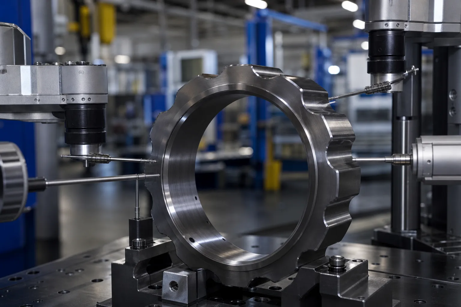
*Inženýrský koncept ilustrace. Ukazuje, že rotační signál může zahrnovat tvarovou variaci; nejedná se o výsledek měření pro zákaznický díl ani o předepsané nastavení kontroly.*
Před čtením měřidla pojmenujte charakteristiku
Kulatost popisuje podmínku tvaru průřezu. Ohyb osy popisuje prostorovou dráhu referenční osy. Házení je rotační měření vzhledem k nastavení základny a může zahrnovat více přispěvatelů. Koaxialita, soustřednost a válcovitost mají také odlišné definice a požadavky na kontrolu. Výkres musí identifikovat, která charakteristika řídí přijetí.
| Signál nebo charakteristika | Diagnostická otázka |
|---|---|
| Kulatost / lobování | Mění se místní poloměr, když se sekce otáčí? |
| Osový ohyb | Mění referenční osa polohu podél délky? |
| Výběh | Které datum, podpěry a sondová stanice vytvářejí čtení? |
| Koaxiální vztah | Je více prvků porovnáváno s definovanou společnou osou? |
| Signál zařízení | Změní opětovné usazení nebo změna orientace podpěry výsledek?? |
Vidět přímost hřídele, házení a TIR a souosost versus házivost pro související terminologii.
What a Rotating Trace Is Made Of
A probe reading taken while a part rotates is, mathematically, a mix of components that repeat once, twice, three times and more per revolution. Reading the mix is the core diagnostic skill. A once-per-rev component means the surface is, on average, further from the rotation axis on one side than the other — which is the signature of either an axis offset between the part’s reference geometry and the rotation axis, or of a bent axis displacing the section as a whole. A twice- or three-times-per-rev component means the section is oval or lobed: the local radius itself changes around the circumference, a form condition of the cross-section that no amount of axis correction removes. Higher-frequency content usually reflects surface texture, keyways and interrupted features, or vibration entering through the supports.
The decisive separation between the two once-per-rev causes is axial. A true bend displaces different stations by different amounts and often in different directions, so the once-per-rev component’s amplitude and phase change as the probe moves along the part. A pure eccentricity condition — centers offset, seat offset, chuck runout — produces a once-per-rev component that keeps the same phase and proportional amplitude at every station. One trace at one station cannot distinguish them; a short axial map routinely can. That is the reasoning behind the multi-station discipline above, and behind multipoint measurement arrangements that read several stations in one setup.
Where Lobing Comes From
Lobing is rarely random — it carries the fingerprint of the machining that produced the surface, which is what makes it diagnostic. Three-lobe out-of-roundness is the classic signature of parts ground on centerless machines, where the part floats between wheel, regulating wheel and blade and the geometry locks into a three-point stability condition. Even-lobe ovality traces back to opposing clamping or distortion relieved after machining — a thin sleeve released from a chuck, a part that relaxed after heat treatment. Odd lobing beyond three appears with certain workholding arrangements and with relapsing of interrupted cuts. Knowing the part’s process route therefore tells you what lobing to expect and whether an observed lobe count is a workpiece reality or an artifact of the current setup: a lobe count that changes when the part is reseated in different orientations is being generated by the setup, not the part.
Nejprve zkontrolujte datum a nastavení
Před výkladem dílu, ověřte vlastnosti středu, čepy nebo jiné referenční plochy, podmínka podpory, čistota, kontakt sondy, způsob rotace a axiální stanice. Poškozený střed, otřepy, špinavé sedadlo, nesprávná podpěra nebo kontakt sondy na přerušené ploše může způsobit zjevné házení, které nepředstavuje ohyb osy.
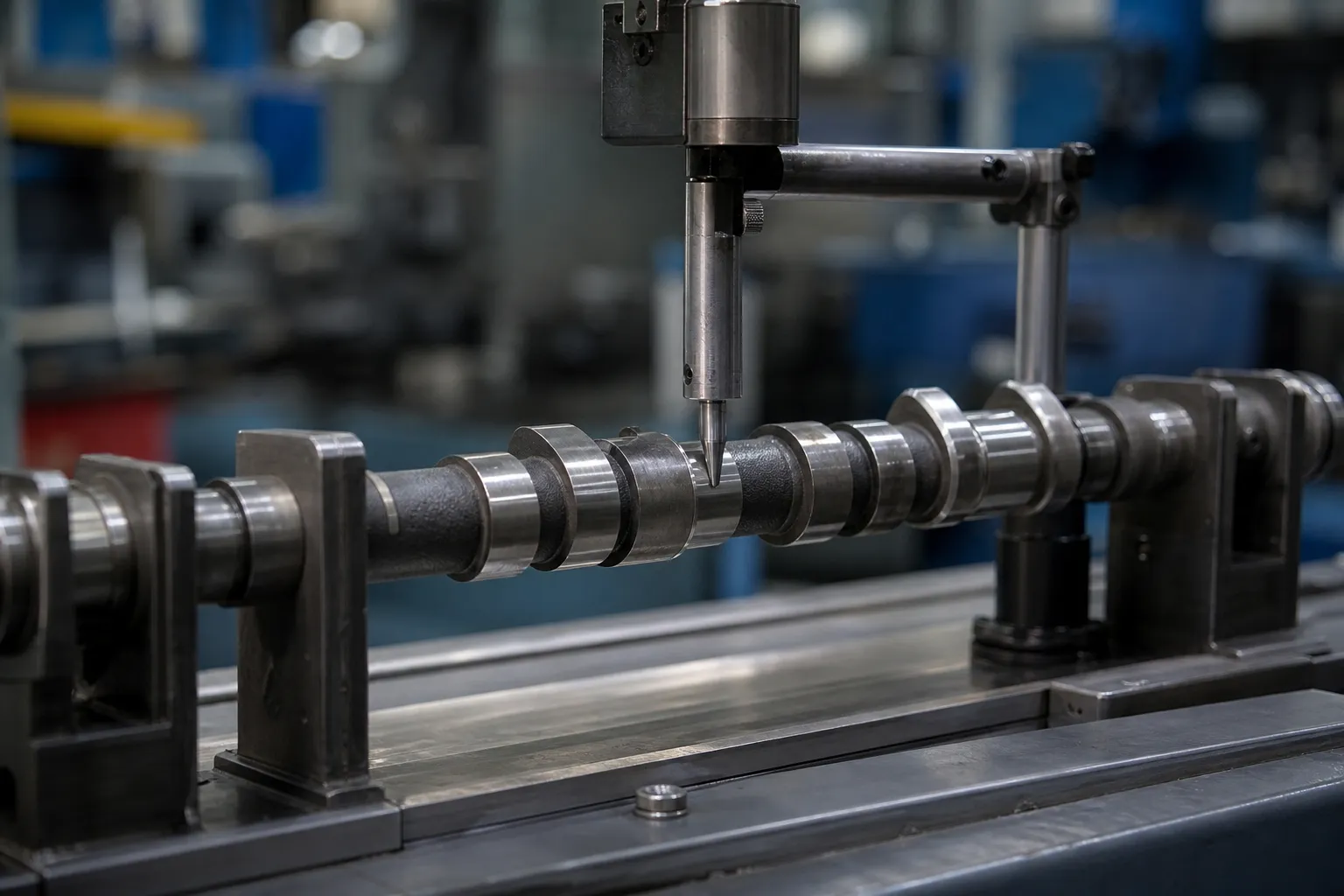
*Inženýrský koncept ilustrace. Ilustruje měření žurnálu s ohledem na funkce; skutečné údaje, dráhy sondy a úhlové masky závisí na řízeném obrobku.*
Použijte kontrolu opětovného usazení/opakování a porovnejte více stanic. Pokud se trasování po opakování nastavení podstatně změní, před použitím korekční síly prozkoumejte realizaci upínadla nebo základny.
Porovnejte více stanic a orientací
Osový ohyb obvykle vyžaduje axiální mapu. Lokální zaoblení nebo laloky se mohou objevit na jedné stanici, ale ne na jiné. Jediný údaj celkového ukazatele v jednom bodě nemůže prokázat, který přispěvatel dominuje. Zaznamenejte umístění stanic, orientace, referenční stav a trasování nebo vypočítaný výsledek požadovaný při přejímacím řízení.
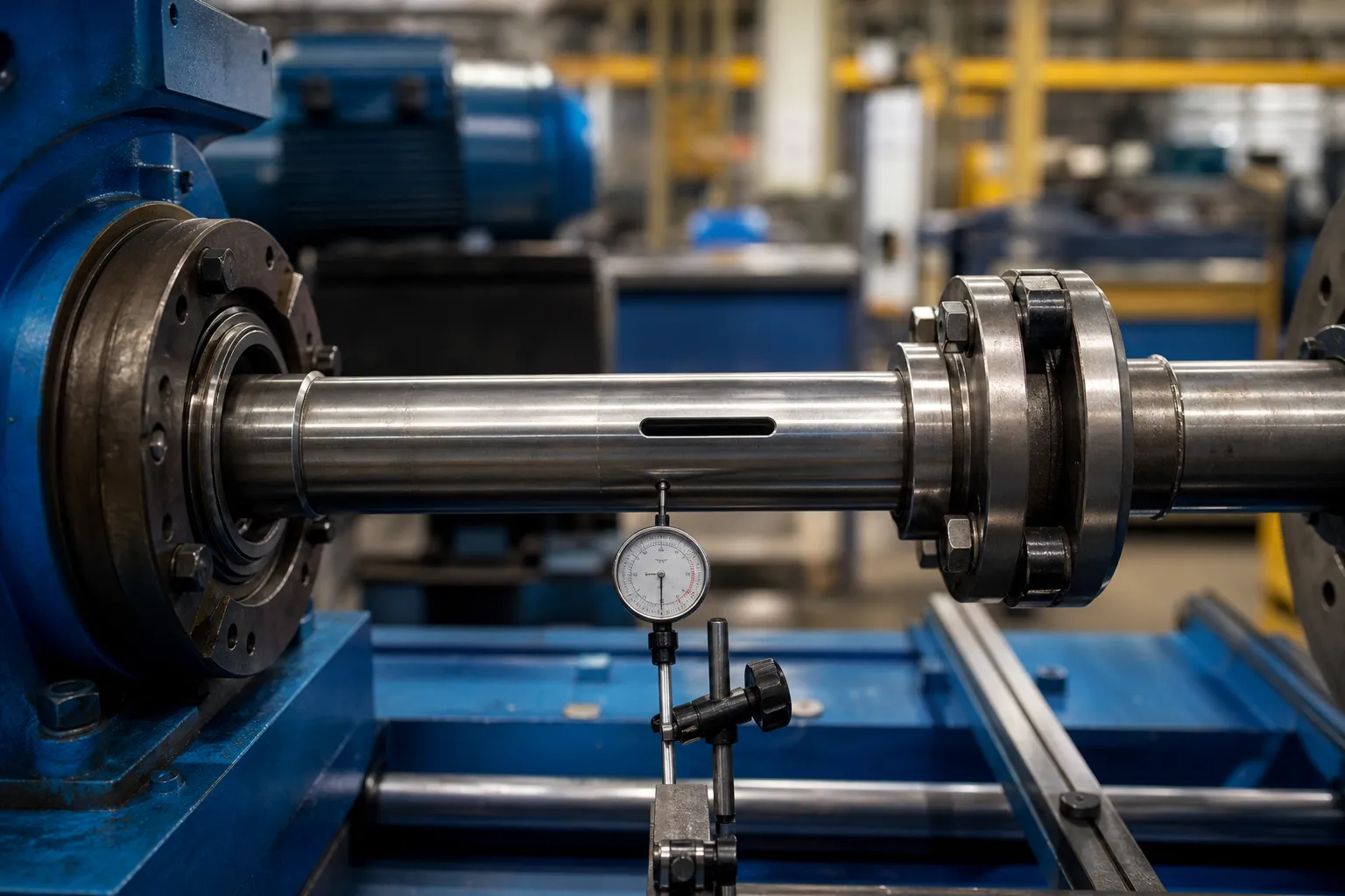
*Inženýrský koncept ilustrace. Představuje otázku rotačního měření s mnoha funkcemi, není schváleným zařízením nebo závěrem, že pozorovaný signál je ohnutý.*
Separating Spindle Error From Part Error
On any rotating instrument, the reading contains the part’s geometry plus the rotation error of the instrument itself — spindle runout, bearing wander, support eccentricity. Precision metrology has standard separation techniques for this, and their logic is worth knowing even when the full apparatus is not available. Reversal methods measure the part in one orientation, then rotate the part exactly half a revolution relative to the fixture and measure again: part error keeps its sign in part coordinates while setup error keeps its sign in machine coordinates, so combining the two traces separates them. Multistep methods extend the same idea through a series of indexed orientations. On a production straightening machine, the practical descendants are simpler: reseating the part in a different clocking orientation and checking whether the trace rotates with the part or stays fixed in the machine tells most of the story, and comparing readings before and after swapping a support identifies which element contributes what.
These checks cost minutes and prevent the most expensive mistake on this page: correcting a bend that lives in the bench. They also make the eventual correlation to the customer gauge meaningful, because both sides of that comparison are then measuring parts rather than setups — the premise underlying měřidlo R&R studies on straightening lines.
A Practical Diagnostic Sequence
The checks above assemble into a fixed order of operations that experienced lines follow before any correction decision. První, clean and inspect the seating features — centers, deníky, support vee blocks — for damage, burrs and debris, since the cheapest explanation is always the setup. Druhý, take a trace, reseat the part in the same orientation, and retrace: disagreement beyond the setup’s established repeatability stops the investigation at the fixture. Třetí, reseat in a rotated orientation: a trace that follows the part is a part signal; one that stays fixed in the machine is a machine or fixture signal. Fourth, map at least three stations along the length and note how the once-per-rev component’s amplitude and phase behave: varying amplitude and rotating phase indicate bend; constant phase with proportional amplitude indicates eccentricity. Fifth, look at the lobe content in relation to the part’s machining history before believing any form conclusion. Only then choose the response — correction for confirmed axis bend within approved zones, or the alternative routes for everything else, with the released-state condition treated per loaded versus released measurement.
The sequence exists because each step filters a class of false positives that would otherwise survive to the next. Skipping ahead to correction is how parts get pressed for eccentricity fixtures, ovality and chucking artifacts — damage that no later measurement undoes.
Vyberte odpověď z diagnostiky
Pokud důkazy podporují stav ohybu osy a existují schválené zóny kontaktu/podpory, kandidátní narovnávací cesta může být vyhodnocena pomocí vzorového testu. Pokud je signál hlavně kulatost, přerušená geometrie, problém data, chyba upínacího zařízení nebo vztah samostatného prvku, může být vyžadován jiný proces nebo kontrola kontroly. Nepoužívejte rovnání ke kompenzaci problému s měřením.
Pro řízenou lokální korekci, vidět rovnání bodovým lisem. Pro korelaci s metodou výstupní kontroly, see machine gauge versus customer gauge correlation.
Ověřte pomocí měřidla zákazníka
Plán vzorků by měl obsahovat známé/referenční podmínky, pokud jsou k dispozici, opakujte nastavení, více stanic, měření uvolněného stavu, identifikace dílů a přípravků, uchovávání nezpracovaných dat a korelace zákazník-měřidlo. Výsledek by měl uvádět, která charakteristika byla vyhodnocena a která nejistota nebo omezení nastavení zůstávají.
FAQ
Znamená vysoké TIR vždy, že hřídel je ohnutá?
Žádný. TIR může obsahovat datum, kulatost, příslušenství a další přispěvatelé. Nejprve diagnostikujte nastavení a více stanic.
Umí narovnání správné kulatosti?
Ne jako obecný závěr. Kulatost je jiná geometrická podmínka a může vyžadovat jiný proces nebo cestu kontroly.
Proč opakovat nastavení?
Opětovné čtení po opětovném usazení pomáhá odlišit signál obrobku od podpory, datum nebo variace přípravku.
What does a three-lobed trace usually indicate?
Most often, a surface produced by centerless grinding, where the three-point contact of wheel, regulating wheel and blade locks the section into a three-lobe form condition. It is a cross-sectional form issue, not an axis issue, and it should be verified against the part’s machining history before any response is chosen.
How can I tell eccentricity from bend with one probe?
Move the probe along the part and watch the once-per-rev component. Bend shows varying amplitude and shifting phase between stations; eccentricity keeps the same phase and proportional amplitude everywhere. If the probe cannot move, mapping several stations with a moved setup achieves the same separation at the cost of reseating discipline.
Does reseating the part in a different orientation really separate machine error?
Ano, in its simplest form. Part error rotates with the part; machine and fixture error stay fixed in machine coordinates. Comparing traces at two clockings shows which class dominates the reading. Formal reversal and multistep methods refine the same principle when numbers, not just classification, jsou vyžadovány.