
Rovnání bodovým lisem je metoda řízené lokální korekce, ne pouze lisování tam, kde díl vypadá ohnutý. Proces musí propojit platnou mapu geometrie se schváleným datem, opěrné body, reakční cesta, povolená opravná místa, přírůstkové řízení a přeměření uvolněného stavu. Bez té smyčky, zdvih lisu může vytvořit značku, přesunout sousední prvek nebo snížit dočasný údaj indikátoru, aniž by byl splněn skutečný požadavek na přijetí.
Toto je procesní rámec. Nevyžaduje lisovací sílu StraighteningTech, mrtvice, řídicí algoritmus, materiálový rozsah, přesnost, doba cyklu nebo kompatibilita obrobku. Tyto hodnoty vyžadují kontrolu výkresu a ověřené vzorky.
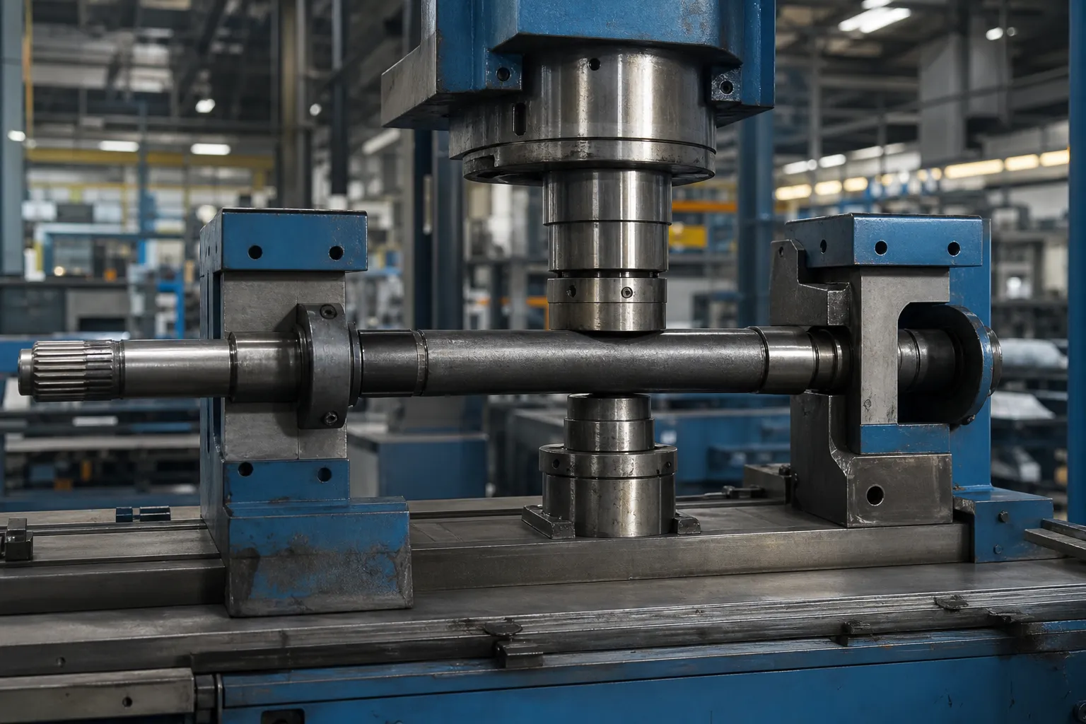
*Inženýrský koncept ilustrace. Ukazuje možný kontext korekce tisku pro konkrétní rodinu obrobků, nejde o univerzální procesní recept nebo ověřenou místní kapacitu.*
Definujte, co proces opravuje
Požadovanou charakteristikou může být přímost na rozpětí, radiální házení vzhledem k referenční ose, boční zametání, lokální vztah prvku nebo jiná řízená geometrie. Před výběrem lisu musí být pojmenován. Chyba kruhovitosti, povrchové přerušení, Signál zařízení nebo úmyslné prohnutí nelze opravit, jako by šlo o stejný druh ohybu.
Použití přímost hřídele, házení a TIR při rotační kontrole dílu. Trubice, profil, jaro, prstencové a svařované obrobky vyžadují vlastní geometrii a hranice procesu.
Vytvořte počáteční mapu chyb
Plán měření by měl určit schválený údaj, orientace dílu, axiální stanice, podmínka podpory, metoda senzoru a opakování/kontrola usazení. Jediný odečet středního bodu může vynechat více ohybů nebo si splést gravitační prohnutí a variace uchycení s geometrií součásti.

*Inženýrský koncept ilustrace. Ilustruje mapu měření před korekcí; skutečné umístění stanic, sondy a vztažný bod musí být stanoveny z kontrolovaného výkresu.*
| Vstup pro zmrazení | Rozhodnutí to podporuje |
|---|---|
| Výkresový základ a přejímací pravidlo | Určuje, co musí měření představovat |
| Počáteční geometrická mapa | Identifikuje korekční zóny kandidátů a riziko interakce |
| Schválené podpěry a reakční body | Zabraňuje silové cestě ve vytvoření nechtěného signálu |
| Chráněné vlastnosti a povrchové limity | Určuje, kde je kontakt zakázán |
| Fáze materiálu a procesu | Definuje možnou reakci, odpružení a omezení po proudu |
The Mechanics of a Point-Press Stroke
A point-press correction is a three-point bend executed on purpose. Two supports and one press point form a loading frame: the press pushes the section toward the supports, bending moment peaks at the press point and falls toward the supports, and the outer fibers at the correction location pass yield while the core of the section stays elastic. When the force is released, the elastic core tries to spring the section back while the yielded fibers hold their new shape — the permanent set is the difference, and the art of the process is delivering just enough plastic work to land the released part inside tolerance. Three consequences follow directly from this picture. The correction is local: the plastic zone concentrates around the press point, which is why error maps guide where to press rather than intuition. The process is self-limiting only if treated incrementally: a single stroke sized optimistically cannot be un-pressed. And the section’s own geometry — its stiffness variation, its transitions, its prior deformation history — modulates everything, which is why identical stroke settings do not transfer blindly between diameters, materials or lots, and why reverse-loading effects, as described for Bauschingerův efekt, change the response of a part that has already been corrected once.
Support Span Is the Primary Tuning Parameter
Operators reach for force when they should reach for geometry. Moving the supports changes the correction before any force value is touched: supports spread wide give a long, gentle bending field — the same press force produces a larger deflection spread over a longer zone, appropriate for a single broad bow; supports close in around the correction point concentrate the same energy into a short, deep correction, appropriate for a local kink but harder on the surface and the section. Span also sets the mechanical advantage of the stroke: the closer the supports, the more force the same correction demands, which is why narrowing the span on a stiff section quickly reaches the machine’s or the part’s limits. Two practical rules fall out. První, choose span from the error map’s wavelength — long bows get long spans, kinks get short ones — and document the choice in the setup record, because span is a process parameter like any other. Druhý, treat support condition as part of the tooling: kontaktní geometrie, cleanliness and wear change the reaction path silently, a surface-protection tooling discipline applies to supports exactly as it does to the press nose.
Vyberte podpory a opravné body společně
Lisovací bod nelze vybrat nezávisle na jeho podpěrách. Rozteč podpory, tuhost sekce, směr síly a kontaktní geometrie vytvářejí reakční dráhu. Špatná podpora může způsobit, že místní tisk bude vypadat efektivně, zatímco přenese chybu jinam nebo poškodí funkci.
Před ukázkovým pokusem, dokument:
- místa podpory a reakce, včetně bezkontaktních zón;
- opravný bod, směr síly a povolená orientace;
- kontaktní materiál, kontroly čistoty a značení;
- maximální přírůstková oprava a počet pokusů;
- plán měření odpružení/uvolnění;
- tvrdé vyřazení a podmínky technické kontroly.
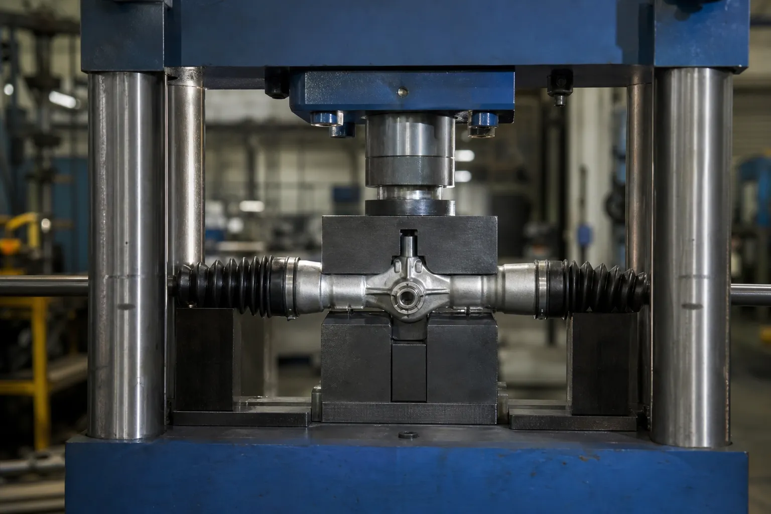
*Inženýrský koncept ilustrace. Ukazuje koncept přírůstkové korekce; nepředepisuje zatížení lisu, mrtvice, nástroj nebo schválený korekční bod pro jiný obrobek.*
Opravte postupně a znovu zkontrolujte po uvolnění
Sekvence uzavřené smyčky je:
- identifikovat řízenou rodinu obrobku a revizi výkresu;
- zkontrolovat poškození, špatná část, zakázaný stav povrchu nebo deformace mimo rozsah;
- načtěte schválený vztažný bod a ověřte usazení;
- změřte mapu počáteční geometrie;
- vyberte povolený plán podpory a oprav;
- použijte inkrementální korekci v rámci hranice vzorku-testu;
- úplně uvolnit sílu, svorky a omezení;
- přeměřte všechny požadované stopy a zaznamenejte výsledek;
- nasměrujte díl do OK, NOK nebo technická revize.
Konečné přijetí je po propuštění. Odečet, kdy součást zůstává pod tlakem lisu nebo uchycením, nelze použít jako důkaz konečného výsledku.
Springback as a Process Variable, Not a Constant
Because the released shape is set by the competition between yielded fibers and the elastic core, the same stroke delivers different permanent set on parts that differ in material condition, section or prior history. That is springback as a process variable, and treating it as a fixed correction factor is how lines end up oscillating around tolerance. The discipline that handles it honestly is described for kompenzace odpružení při rovnání hřídele: learn the response on representative samples, correct incrementally, and re-learn when the material lot or part revision changes. A related trap deserves its own sentence: pressing a part past nominal on purpose — overshoot to pre-compensate springback — is legitimate within a validated recipe and a defined limit, but repeated overshoot-and-press-back cycles accumulate reverse-loading damage, and the correction-attempt limit exists precisely to stop that sequence before it becomes a cracking risk, za the integrity-review framework.
Reading the Data Between Strokes
Each stroke in the incremental loop is also an experiment, and the data between strokes tells the operator when to continue and when to stop. A healthy convergence shows the remaining error shrinking by a decreasing amount each stroke — the response per stroke falling as the part approaches target, which is the natural signature of a stable correction. Three patterns break that signature and each demands stopping rather than pressing harder. No progress: the geometry stops responding, meaning the process is no longer engaging the error — the correction point, support condition or part state has changed under the operator. Diminishing returns with rising effort: each stroke moves the part less while the press works harder — the section is fighting back through strain hardening, and continuing trades diminishing geometry gain for accumulating material damage. Oscillation: the part crosses nominal in alternate directions stroke by stroke — the correction rule is over-reacting, often because it was calibrated on a different response, and the fix is the recipe, not the part. Building these three stop patterns into the operating procedure converts the between-stroke data from noise into the line’s earliest quality alarm.
Poznejte, kdy bodové stisknutí není správná cesta
Bodové lisování není výchozí metodou pro každý produkt. Nepřetržitý drát, tenkostěnná trubka, asymetrický profil, kroužek, jaro, část kritická z hlediska únavy nebo citlivá na svařování může vyžadovat jiný přístup, specializované nástroje nebo samostatné přezkoumání procesu. Vidět lisování versus rovnání válečkem pro hranici výběru metody.
Vzorový test a přijetí
Vzorový plán by měl zahrnovat normální a nejhorší případ příchozích částí, surové před/po geometrii, opakovatelnost opětovného usazení, povrchová kontrola, požadované kontroly materiálu/vlastností, limit maximálního pokusu a korelace s referenčním měřidlem zákazníka. Pokud praskne, tvrdost, NDT, broušení nebo vyvážení jsou relevantní, zůstávají nezávislou odpovědností za přijetí.
Použití zkouška rovnání vzorku a přejímka k definování důkazů požadovaných před produkčním tvrzením nebo rozhodnutím FAT/SAT.
FAQ
Může bodové lisování zaručit specifickou přesnost?
Žádný. Dosažitelný výsledek závisí na obrobku, datum, hmotný stav, podpora, kontaktní zóny, odezva vzorku a dohodnutá metoda kontroly.
Je nejvyšším indikačním bodem vždy korekční bod?
Žádný. Korekční bod musí být vybrán z geometrické mapy a schválené reakční dráhy, ne z izolovaného vizuálního nebo indikátorového pozorování.
Může lis opravit trhlinu nebo vyměnit NDT?
Žádný. Rovnání neopravuje vady materiálu a nenahrazuje kvalifikované kontrolní procesy.
Why does the same press stroke move two identical-looking parts differently?
Because released geometry depends on material condition, section detail and prior deformation, not on appearance. Different lots, heat-treatment states or a previous correction cycle all change the plastic-versus-elastic balance the stroke works against. The remedy is learning the response per family on samples and re-checking it when lots change.
When should supports be moved closer together?
When the error map shows a short, local kink rather than a broad bow. A narrow span concentrates the correction where the error lives; a broad span spreads it. The span choice belongs in the documented setup, because it changes both the correction shape and the force the part must carry.
What does it mean when a part stops responding to corrections?
The process is no longer engaging the error — a no-progress condition. Causes range from a changed correction point to a setup or part-state shift, and the defined response is to stop and route the part to review, not to increase force. Continuing to press spends the part’s deformation budget on nothing.
Rovnání před vs. po broušení
Pro není udržována žádná nezávislá kanonická stránka rovnání před vs po broušení protože průmyslová poptávka po přesné shodě je malá. Sekvence fází, do kované tyče patří přídavek zásoby a přenos nulového bodu, stránky s bodovým lisem a vícebodovým procesem. Před uzamčením výrobní cesty si ověřte, zda broušení odstraňuje materiál, který by znehodnotil dřívější měření přímosti.
Silové křivky posunutí při narovnávání
Věnovaná stránka pro rovnání síla displacement curve guide není udržován bez ověřeného požadavku dotazu. Interpretace Force's Troke, bezpečné limity a podmínky zastavení procesu jsou vysvětleny v point-pressu, vícebodové stránky a stránky s detekcí trhlin. Jakýkoli alarm založený na křivce musí být ověřen na reprezentativních dílech a nikoli zkopírován z jiné materiálové skupiny.
Point-press work lives or dies by stroke control – read why over-correction cracks parts before you size a machine, then use the návod k výběru rovnačky to match press concepts to your part family.