
Các bộ phận kết cấu đúc lớn có thể phức tạp, hình học tường mỏng và nhiều giao diện chức năng. Một hệ thống làm thẳng 3D đáng tin cậy phải kiểm soát chiến lược chuẩn và vật cố định, trạng thái đo, khái niệm hiệu chỉnh đa điểm, rủi ro tiếp xúc/bề mặt, đánh giá rủi ro crack và phát hành hình học. Báo chí chung chung hoặc kiến trúc của đối thủ cạnh tranh đã được công bố không phải là bằng chứng cho thấy nhà cung cấp có thể thực hiện công việc này.
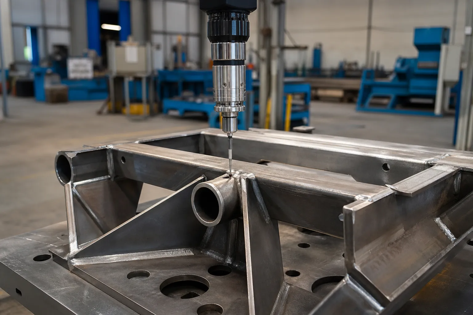
*Minh họa khái niệm kỹ thuật. Nó không thể hiện trình tự hiệu chỉnh đã được xác thực, bộ truyền động hoặc kết quả của bộ phận cấu trúc.*
Đừng tuyên bố ép buộc, số lượng thiết bị truyền động, thời gian chu kỳ, sức chịu đựng, tỷ lệ phát hiện vết nứt hoặc kiểu đúc tương thích mà không có bằng chứng dự án. Những giá trị này không thể được chuyển nhượng từ hệ thống giấy hoặc hệ thống của đối thủ cạnh tranh.
Why Large Castings Move After Casting
Cast structural parts distort because solidification and cooling are never uniform across a section of varying thickness. Thick features cool slowly and contract later than thin walls, so the casting leaves the die or mold with a locked-in residual stress field. That stress field is not visible on the part — it only announces itself later, when something changes. Ejection, trimming, xử lý nhiệt, shot blasting, and above all machining all remove or redistribute constraint, and the part moves toward a new equilibrium. A rear-structure casting that measured acceptable in the as-cast state can drift out of position tolerance after critical interfaces are machined, because removing material from one face releases the balancing stress on the opposite side.
This is why distortion control on structural castings is a sequence problem, not a single-press problem. The timing of the straightening operation inside the process route — before stress relief, sau khi gia công thô, before finish machining — changes both how much correction is needed and how stable that correction remains. Each of those routes has different risk: correcting an as-cast part may be undone by later machining, while correcting a finish-machined part risks damaging functional surfaces. The route decision belongs to the responsible process engineer, with the distortion history of the part in view.
What Makes Correction “3D” Instead of Planar
Conventional bar and shaft straightening corrects a centerline that is, to first order, a plane curve: bow in one plane, sometimes bow measured in two perpendicular planes and combined. The machine finds the high point of the bend, supports the part on two anvils, and presses at the peak. The geometry being controlled is a single neutral axis. This is the model behind quá trình làm thẳng trục tự động hoạt động như thế nào, and it assumes a stiff, uniform section.
A thin-wall structural casting breaks those assumptions. The section is not uniform — rails, xương sườn, bosses and window openings give it direction-dependent stiffness, so the same applied force produces different deflection depending on where and in which direction it acts. The deviation is not one bend: it is a combination of bow in one axis, sweep in another, twist about the longitudinal axis, and local displacement of individual functional interfaces — a mounting pad seated high on one end, a bore axis tilted relative to the datum system. The measurand is the position and orientation of each functional interface in the part coordinate system, not a single runout reading. Any correction plan that only chases an overall bow will move interfaces it did not intend to move.
Practically, this means the error map for a structural casting is a table of interface deviations, not a polar diagram of a centerline. It also means correction targets must be prioritized: interfaces with tight position tolerances and mating consequences come first, and secondary geometry is allowed to float inside its own tolerance bands. That prioritization is a drawing-driven engineering decision made before any press stroke is planned.
Datum and Fixture Strategy Comes Before Correction
Measurement and correction of a casting are only as good as the datum system they reference. As-cast surfaces are draft angles and skin — they are neither repeatable nor representative. The part must be located on its drawing-defined machined datums, the same features the customer gauge will use at acceptance. If measurement uses one set of features and the customer gauge uses another, the two systems will disagree by setup error alone, before any real part variation enters. The principles are the same as those covered for lựa chọn mốc đo trục bước, applied to a far less symmetric workpiece.
Fixtures for thin-wall castings carry an additional burden: the clamping and support scheme must not load the part into a false shape. A casting supported at the wrong points deflects under its own weight and under clamp force, and the measurement system will faithfully record that deflection as part error. Supports belong under stiff sections — ribs, rails, boss clusters — not in the middle of window openings. Every fixture concept should be proven by reseating: đo lường, unload, reload, measure again, and treat the spread between those readings as the floor of what the system can resolve. If reseating repeatability is poor, no amount of correction accuracy downstream will close the loop, a lesson that also drives máy đo R&R practice for straightening lines.
Correction Concepts and Their Limits
The mechanical idea behind correcting a casting is selective local plastic deformation: apply force at chosen points to shorten one side of the structure or shift its stiffness balance, so the released part settles closer to nominal. Two families of concepts exist. Point pressing — the same family described for nhấn điểm làm thẳng — concentrates deformation at a support-and-press location and is best suited to localized deviations on stiff sections. Distributed or multi-point methods spread smaller corrections over several locations to reshape a longer span. Which concept fits a given casting depends on where the deviations sit and how the stiffness varies between them, which is exactly why a generic press specification answers nothing.
Three limits bound any correction route. Đầu tiên, cast aluminum has limited ductility compared with drawn bar stock, and a thin-wall section concentrates strain: the crack-risk review — where cracks are likely, how they will be looked for, and who accepts the result — must be settled before the first trial stroke, not after a suspect part appears. Thứ hai, correction interacts with the residual stress field that caused the distortion. A correction imposed without regard to that field can relax during subsequent handling, machining or thermal exposure; stress behavior after correction is a topic treated separately for làm thẳng sau khi xử lý nhiệt. thứ ba, over-correction on a casting is usually not recoverable by pressing back, because reverse loading accumulates low-cycle fatigue damage in the section.
The discipline that manages all three limits is the same incremental loop used on precision shafts: small correction, giải phóng, đo lại, decide. The measure–correct–release–remeasure cycle described for long structural sections such as elevator guide rails scales down to castings in principle, but with one added rule: because interface positions rather than a single centerline are the target, each loop must re-read the interface table, not just the worst single reading.
Đo lường, Tính toàn vẹn và phát hành phải đồng ý
Bản ghi phát triển phải bảo toàn hình học đến, thiết lập mốc/cố định, phương pháp đo/phiên bản dữ liệu, trình tự hiệu chỉnh, hình học phát hành, phát hiện và xử lý bề mặt/kiểm tra. Nếu cần phải kiểm tra tính toàn vẹn, phương pháp của nó, phạm vi và thẩm quyền chấp nhận phải được xác định bởi đội ngũ kỹ thuật và chất lượng có trách nhiệm.
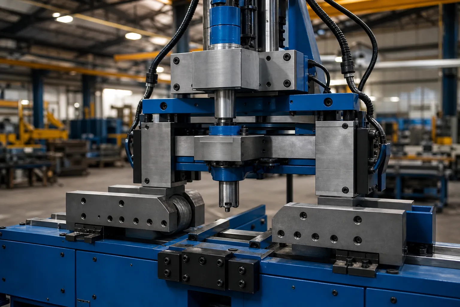
*Minh họa khái niệm kỹ thuật. Nó không phải là bằng chứng về thiết bị có sẵn, thiết kế an toàn hoặc ứng dụng đúc giga.*
Nhìn thấy độ lặp lại của vật cố định và chỗ ngồi chuẩn Và độ không đảm bảo đo trong kiểm tra độ thẳng để kiểm soát có liên quan; không cung cấp bằng chứng về khả năng đúc 3D.
Bằng chứng cần thiết trước bất kỳ khiếu nại nào của nhà cung cấp
Quyết định xuất bản MỞ yêu cầu dự án casting được ủy quyền thực sự, mốc thời gian và vật cố định 3D được xác định bằng bản vẽ, dữ liệu đo lường trước/sau/phát hành, hồ sơ đính chính, đánh giá bề mặt/tính toàn vẹn, chấp nhận mẫu và ủy quyền của khách hàng. Cho đến lúc đó trang này vẫn là một khuôn khổ nghiên cứu. Đối với một cuộc thảo luận kỹ thuật có phạm vi, liên hệ với StraighteningTech với thông tin dự án được ủy quyền.
Xác thực bắt buộc trước khi yêu cầu hệ thống
Any system claim for giga-cast correction needs a defined workpiece scope, calibrated datums and fixtures, dữ liệu đo lường có thể theo dõi, and correlation with the customer’s own gauge. A generic machine capability is not a verified result for this topic.
Câu hỏi thường gặp
Can a giga-cast structural part be straightened on a bar straightening machine?
Not as a drop-in. Bar straightening machines assume a uniform stiff section and a single centerline error. A thin-wall structural casting has direction-dependent stiffness, twist and interface-position deviations, and needs a datum, fixture and measurement concept built around its drawing — plus a crack-risk review appropriate to cast ductility. Some underlying correction physics is shared; the workholding, measurement and validation are not.
Should stress relief come before or after straightening a casting?
That depends on the distortion history and the process route, and it is a decision for the responsible process engineer. Correcting before stress relief risks later relaxation of the correction; correcting after removes one instability source but may face harder material. What should be non-negotiable is that the choice is deliberate, documented, and consistent between the trial and production.
What evidence should a buyer request before accepting a 3D straightening proposal?
A drawing-defined 3D datum and fixture concept, measurement data in the as-received and released states, the correction record for every trial part, an integrity or crack-inspection scope agreed with the quality team, and acceptance judged on the customer gauge. A proposal that offers only machine specifications, without those items, is not a proposal for this work.
Tài nguyên công nghệ làm thẳng liên quan
Nhìn thấy quá trình làm thẳng trục tự động hoạt động như thế nào, thử nghiệm và chấp nhận mẫu thẳng Và độ thẳng của trục so với độ lệch tâm so với TIR đối với các ranh giới kiểm soát chung áp dụng trước bất kỳ yêu cầu nào về năng lực trên 3D Làm thẳng các bộ phận kết cấu Giga-Cast.

*Minh họa khái niệm kỹ thuật.*
Giga-casting correction is an automation-first conversation – cái so sánh thủ công và tự động addresses the process jump, và Hộp ROI để làm thẳng tự động addresses the capital question.