
Choosing a wire straightener is not simply a choice between more rolls and a faster machine. The method must match the incoming coil memory, wire section, матеріальний стан, surface requirement, cut length and downstream operation. Payoff behavior, feed traction, cutting and collection can also change the geometry measured after the wire leaves the line.
This guide compares multi-plane roll straightening, rotary straightening and combined routes for cut-to-length production. It is a Tier C engineering framework, not a statement that one method always reaches a particular straightness, speed or diameter range. Final selection must be based on representative coils, the agreed released-sample measurement and a documented reaction plan.

*Source-video frame.*
*Source-video frame.*
*Інженерна концепція ілюстрації. It compares candidate architectures and is not a customer installation or performance record.*
Define the Wire and the Cut-Part Requirement First
The same nominal diameter can behave differently after drawing, теплова обробка, покриття, spooling and transport. Before choosing a straightening head, define both the incoming coil condition and the released cut-part requirement.
| Обов'язковий вхід | Why it changes the decision |
|---|---|
| Круглий, flat or shaped section | Roll groove, contact pattern and whether rotation is acceptable depend on the section |
| Diameter or section range | Determines feasible roll size, guide clearance, feed force and candidate rotary tooling |
| Material and heat-treatment state | Changes elastic recovery, allowable strain and sensitivity to repeated bending |
| акторський склад, helix and torsion | A single-plane correction may reduce one component while leaving another |
| Поверхня, coating and cleanliness | Groove pressure, sliding contact, debris and rotary motion can create unacceptable marks |
| Cut length and support condition | A short piece and a long slender piece can show different released bow under the same setup |
| Довжина, end and straightness requirements | годувати, encoder, cutter and straightener must be validated as one process |
| Downstream forming or assembly | Residual twist, end deformation or surface marks may matter even when the part appears straight |
The acceptance drawing should identify the actual characteristic: прямолінійність центральної лінії, bow over a defined span, maximum gap, free-state profile, довжина відрізу, end squareness, diameter or surface condition. “Straight wire” is not a complete inspection instruction.
How Multi-Plane Roll Straightening Works
A roll straightener guides the wire through a series of offset rolls or bearings. The wire experiences repeated, controlled bending as the roll offsets gradually reduce coil memory. Two or more planes can address curvature in different directions; additional planes or adjustments may be needed when helix or shaped sections make the response directional.
Roll straightening is a candidate when:
- the wire can be guided through controlled grooves without unacceptable marking;
- the correction can be separated into defined planes;
- the product mix benefits from recorded roll positions and repeatable changeover;
- shaped wire must keep a controlled angular orientation;
- the required cut length and released geometry can be demonstrated with the chosen payoff and feed system.
It is not automatically the safer route for every surface. Too much roll penetration, contaminated grooves, the wrong groove profile or unstable wire entry can create scratches, flattening or inconsistent residual stress. The setup must therefore specify roll sequence, groove condition, entry guidance, adjustment method and cleaning controls.
How Rotary Wire Straightening Works
A rotary straightener passes the wire through an arbor or spinner containing offset dies, bushings or guides. The rotating correction field applies bending around the wire axis as the material advances. This can be useful when long cut pieces, complex coil memory or a need for circumferential correction makes a fixed-plane route difficult.
Rotary straightening is a candidate when:
- the wire is round or otherwise compatible with controlled rotation;
- the required length makes residual multi-directional curvature important;
- the material and surface can tolerate the selected rotary contact system;
- arbor speed, line speed and correction setting can be controlled as one recipe;
- the payoff and feed system can present the wire without unstable tension or torsional disturbance.
Rotary does not mean universally better. A rotating arbor can introduce heat, debris, spiral marking or torsional effects if tooling, мастило, speed and material condition are not compatible. Shaped wire, покриття, very soft material or parts with orientation-sensitive features may require a roll route, special tooling or a combined trial.
Roll, Rotary or Combined: Use Conditional Selection
| Decision condition | Roll route to evaluate | Rotary route to evaluate | Combined or trial route |
|---|---|---|---|
| Curvature mainly lies in known planes | Strong candidate | Possible but not automatically necessary | Add another roll plane if evidence supports it |
| Cast and helix are both unstable | Multi-plane setup may work | Strong candidate for round wire | Pre-straighten, then rotary trial |
| Shaped section must keep orientation | Strong candidate with matched grooves | Usually limited unless special tooling proves compatibility | Guided roll route with orientation control |
| Long cut pieces show residual multi-direction bow | Requires long released-sample validation | Candidate for long-length control | Compare both routes on identical coils |
| Surface is easily marked or coated | Use low-friction matched grooves and low contact pressure | Requires a dedicated surface-risk trial | Test both contact systems and cleanliness controls |
| Frequent product changes | Recorded roll settings and quick release may help | Tooling/arbor change and recipe control must be assessed | Select by verified changeover and sample results |
| Intermittent feed or downstream press | Roll or oscillating route may match the cycle | Rotary inertia and synchronization need review | Decouple feed with accumulation where appropriate |
The table defines questions, not guaranteed answers. Material from two suppliers, or even two coil lots, may need different settings. The approved method should therefore be stored as a controlled recipe with its applicable material, coil and part range.
Payoff, Feed and Cutting Can Change Straightness
The straightening head does not operate in isolation. A stable line must manage the whole path from coil to released part.
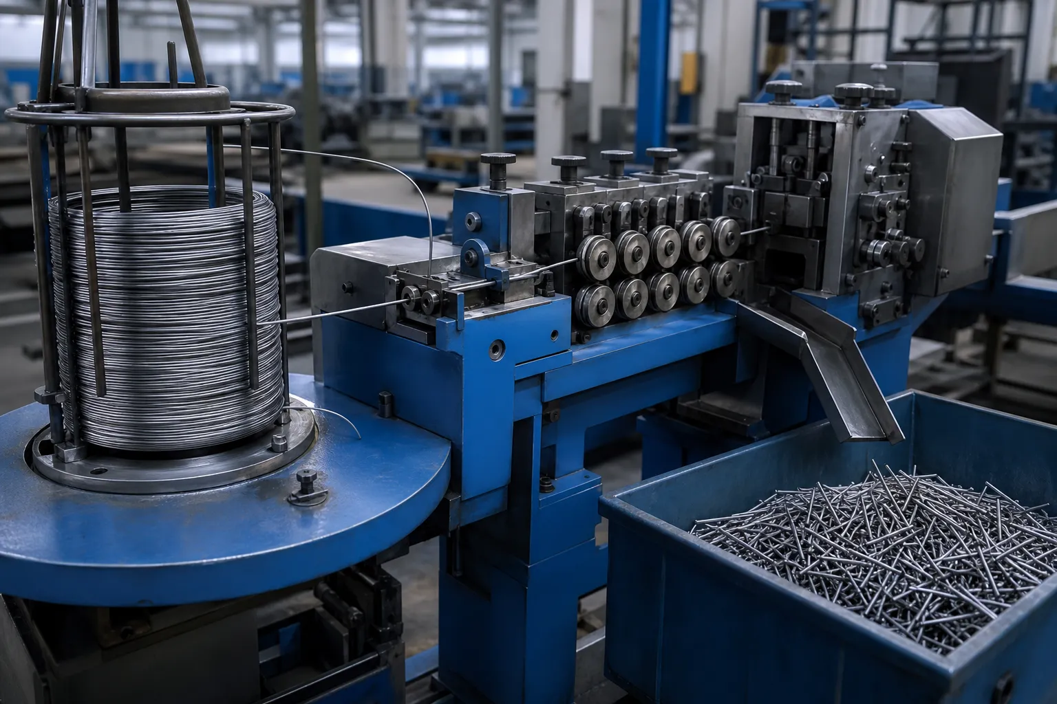
*Інженерна концепція ілюстрації. Component selection and guarding remain subject to line-specific engineering review.*
Payoff and entry condition
A heavy coil, uncontrolled overrun or changing coil diameter can vary entry tension. A powered payoff, dancer, accumulator or controlled turntable may be needed so the straightener is not also pulling unstable coil mass. Entry guides must prevent loops, kinks and side loading without forcing the wire into a false datum.
Feed and length measurement
Feed rolls must generate enough traction without flattening or marking the wire. If length is measured only from a driven roll, slip can create a difference between commanded and actual length. An independent encoder or validated feed correlation may be appropriate, but its pressure and contact position also require control.
Cutting and end condition
The cutter must match diameter, material and end-quality requirements. A stop cut, pneumatic shear, servo cutter or flying shear can affect line continuity, length control and end deformation differently. Cut quality is part of acceptance; it should not be hidden behind a straightness result.
Runout and collection
Long pieces need support after cutting. A sagging runout, a hard impact against a stop or uncontrolled bundling can bend a part after it has left the straightener. Collection design must preserve the condition being measured and prevent accepted and quarantined parts from mixing.
Measure the Released Cut Sample
An in-line guide or feed roll can hold wire in an apparently straight condition. Final acceptance should therefore be based on the cut sample after it is released from straightener, годувати, керівництво, cutter and collection forces, unless a validated correlation proves that an in-line measurement represents the released part.
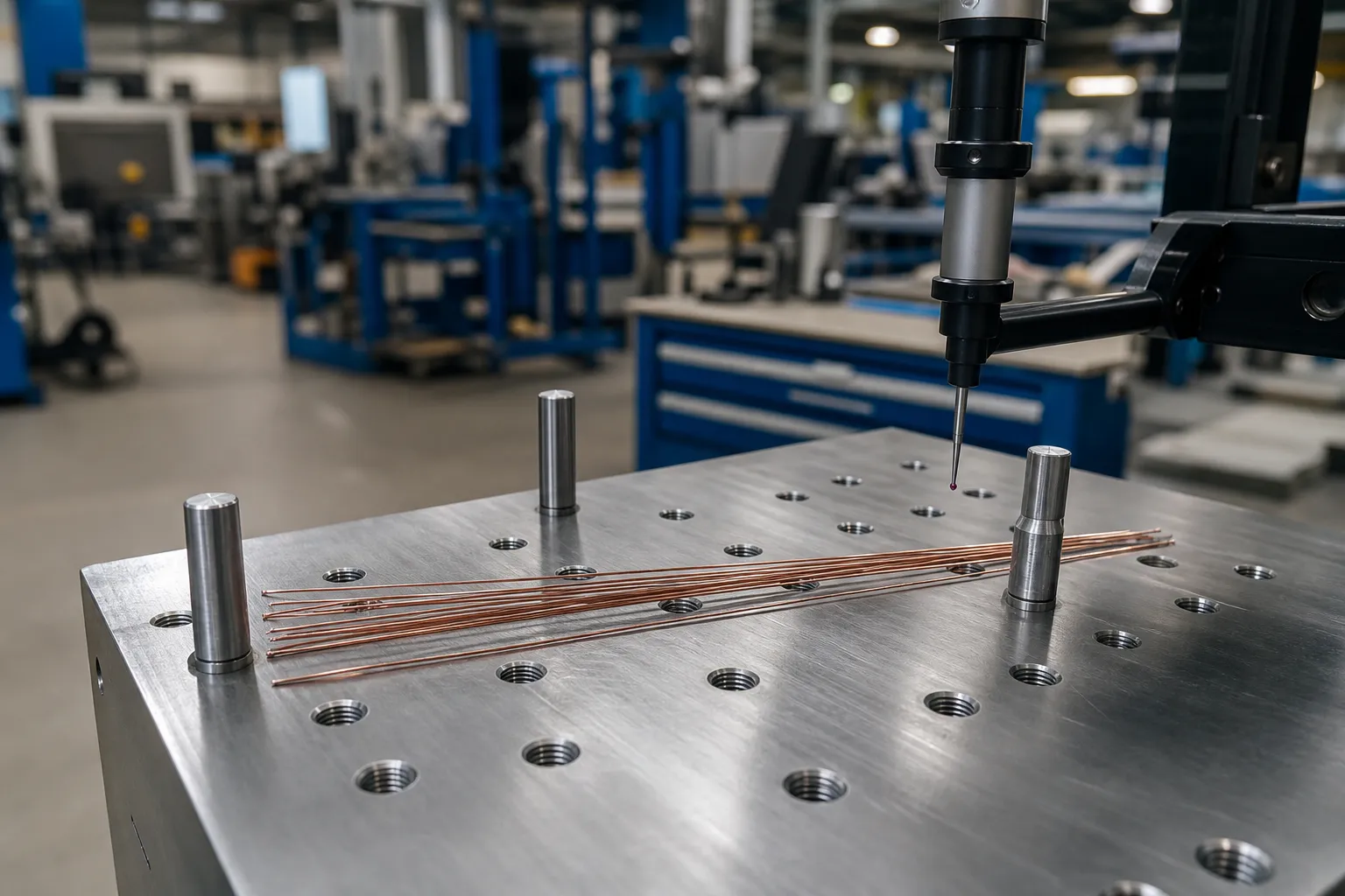
*Інженерна концепція ілюстрації. The support, проліт, instrument and acceptance limits must come from the controlled inspection method.*
План перевірки повинен визначати:
- час кондиціонування після різання, if material behavior requires it;
- free-state support arrangement and span;
- whether the sample is rotated and which orientations are checked;
- прямолінійність, bow or maximum-gap calculation;
- cut length and end inspection;
- діаметр, section and surface checks;
- sample frequency, record fields and measurement-system correlation.
An добре sample meets every required characteristic. А ДОСТАТЬ sample triggers the approved reaction: adjust the validated recipe and run a new confirmation sample, segregate production since the last accepted check, stop the line when required, or reject material outside the allowed rework window. A cut part should not be repeatedly passed through an improvised correction loop unless that route has its own validation.
Build a Representative Coil Trial
The trial should compare methods using material that represents production variation rather than a single easy sample.
| Trial factor | Minimum comparison |
|---|---|
| Coil source | Supplier, heat/lot and coil position when relevant |
| Вхідний стан | акторський склад, спіраль, кручення, surface and dimensional baseline |
| метод | Roll, rotary or combined candidate with recorded settings |
| Line condition | Payoff mode, entry tension, feed pressure, line speed and cutter mode |
| Cut pieces | Short, nominal and long lengths if the product family includes them |
| Released inspection | Така ж підтримка, проліт, орієнтація, gauge and calculation for every route |
| Quality result | Straightness/bow, довжина, закінчується, diameter/section and surface |
| Stability | Repeated samples after startup, adjustment, coil transition and planned stop |
| Розпорядження | OK/NOK, adjustment, rework boundary and affected-batch action |
The result should identify the approved operating window and its exclusions. A successful sample at one diameter, length and coil condition does not prove the entire requested range.
What We Need to Select the Route
Send the wire drawing, section and diameter range, матеріал і стан термічної обробки, coil data, surface requirement, incoming cast/helix examples, cut-length range, required line rate, cutter/end requirement, released-part inspection method and representative coils.
Використовуйте Посібник з випробувань зразків випрямлення та приймання to define the trial and acceptance record, and keep the acceptance terminology distinct with the прямолінійність, Runout and TIR Guide. For application review, зверніться до StraighteningTech with the drawing and coil information.