
Aerospace components earn their tolerances the hard way. A turbine engine shaft spins at high speed in a hot section; a landing gear pin carries impact load on every touchdown; a flight actuator rod positions a control surface thousands of times per flight. When one of these parts arrives at inspection with a bend, the correction has to hit a tight geometric tolerance in a difficult material, without damaging the surface, without hiding a crack, and with a documented record of everything that was done. That is aerospace shaft straightening.
This article explains where straightening sits in aerospace part production, which part families need it, why the materials make it harder, and how the quality-system context changes the way correction work is specified and verified. It complements our part-specific pages on railway axle straightening і правка шпинделя верстата, which apply similar physics under different commercial and regulatory constraints.
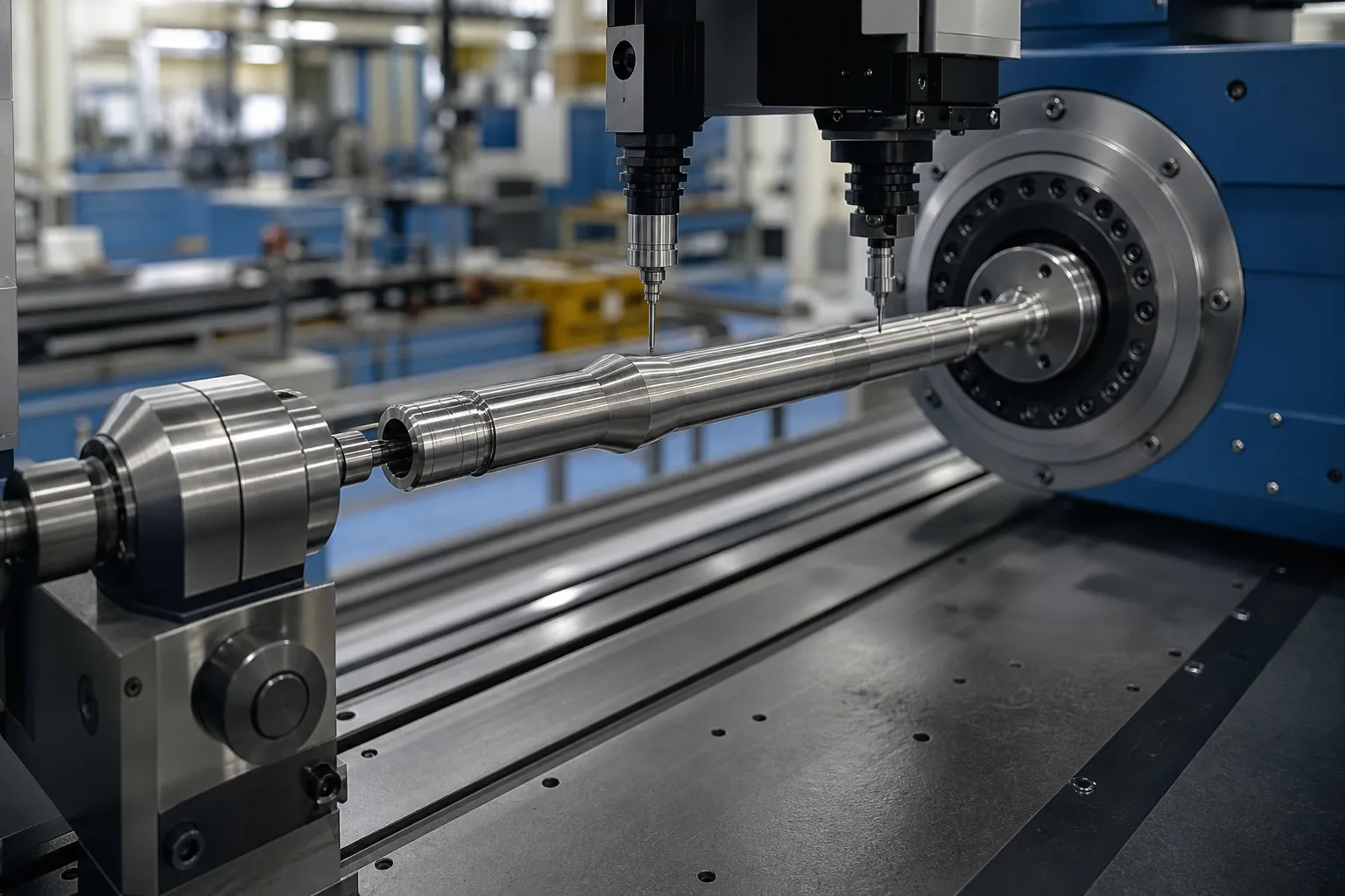
What Makes an Aerospace Shaft Different
Three factors separate aerospace straightening from general industrial practice:
- Матеріали. Nickel-based superalloys, precipitation-hardening stainless steels, titanium alloys, and high-strength low-alloy steels dominate. These materials combine high yield strength – which raises the press force needed for a given correction – with a strong springback response and, in some conditions, sensitivity to overloading. The correction strategy has to respect the material’s tolerance for plastic deformation, not just the target geometry.
- Геометрія. Engine shafts in particular are long in relation to their diameter and usually hollow, with internal features, фланці, and thin-wall sections machined into them. A part that started as a forged billet may have had a large percentage of its mass removed by turning and deep-hole drilling, and every one of those operations changes the residual stress balance. Thin-wall sections also limit how and where the part can be supported and pressed.
- The quality system. Aerospace production runs under AS9100-family quality management, with special-process controls, full material and process traceability, and first-article inspection. A straightening operation on a flight hardware part is not an informal touch-up; it is a defined process with parameters, записи, and acceptance criteria.
None of this changes the underlying mechanics – a bend is still corrected by controlled plastic deformation against properly placed supports, exactly as described in як працює автоматичне рихтування валу. What changes is the margin for error and the amount of evidence required at every step.
Part Families That Need Straightening
Straightening work appears across the aerospace supply chain in several recurring families:
- Engine shafts and spools. High-pressure and low-pressure turbine shafts, fan shafts, and gearbox shafts for turbofan and turboshaft engines. These are the most demanding parts: порожнистий, thin-wall, термічно оброблені, and intolerant of runout at bearing journals and mating splines.
- Structural pins and axles. Landing gear axles, links, and pins, actuation rods, and track components. Typically high-strength steel, often plated or coated, with straightness requirements tied to bearing fit and load distribution.
- Fasteners and engine hardware. Long precision bolts, шпильки, and engine-mount hardware where bend would compromise fatigue life or assembly preload.
- MRO and repair. Overhaul shops straighten worn or service-distorted shafts as part of repair scope, using the same measurement-driven methods against the original drawing limits or approved repair limits.
The mix matters for equipment planning. Engine OEM tiers face series production of a small number of high-value part numbers, where a dedicated, automated straightening cell with full data capture pays for itself in consistency alone. Job shops and MRO facilities see the opposite profile – many part numbers, low volumes per number – and need quick changeover, flexible support tooling, and recipe management more than raw cycle speed. Both profiles exist inside aerospace, and the same quality expectations apply to both.
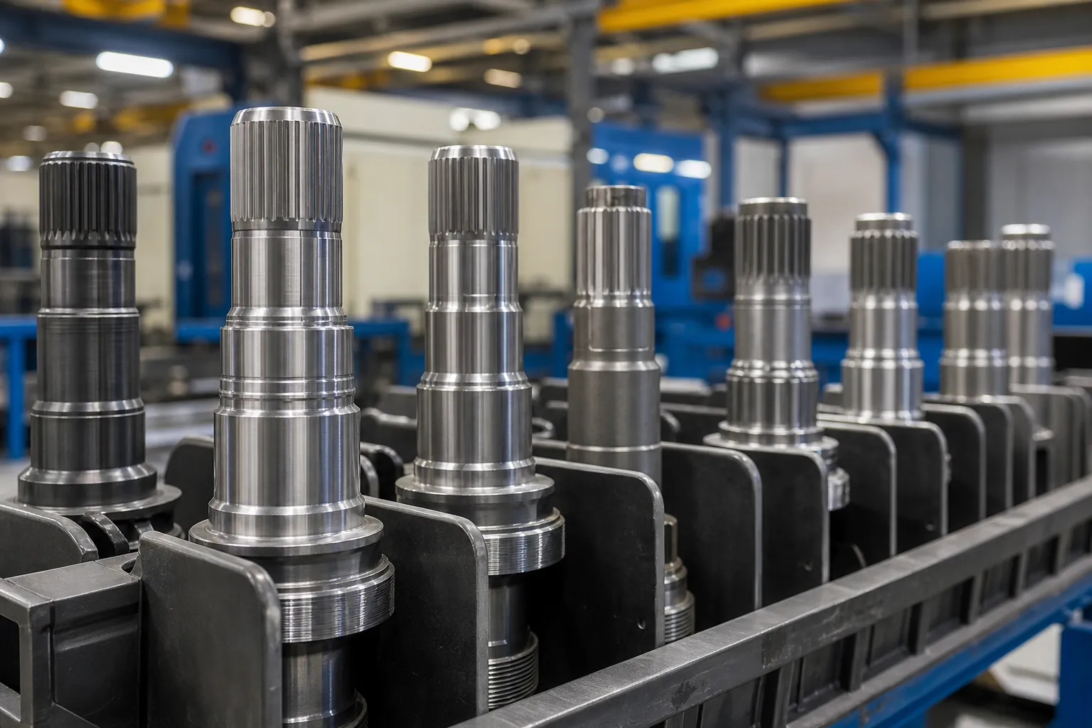
Where the Distortion Comes From
Aerospace shafts accumulate distortion from the same sources as other precision shafts, amplified by the material and geometry:
- Термічна обробка. Solution treating, aging, and case hardening of high-strength alloys release forging and machining stresses and bend the part, sometimes days after treatment as stresses continue to relax. The mechanisms are the ones described in випрямлення після термообробки.
- Deep-hole drilling. Gun-drilling a long bore leaves residual stress in the wall, and the resulting bow frequently appears late. Handling drilled parts is delicate enough that we treat gun drill and deep-hole drill straightening as its own discipline.
- Heavy machining. Rough turning and milling of asymmetric features relieve locked-in stresses from the forging and distort the part as stock comes off.
- Welding and joining. Welded flanges, brazed assemblies, and friction-welded joints introduce local heat distortion on parts that may already be near net shape.
Because several of these sources act progressively, aerospace process plans generally place a measurement gate after each distortion-prone step, with straightening triggered by data rather than by schedule.
Correction Methods Used on Aerospace Parts
Three correction approaches cover most aerospace work:
- Precision press straightening. The part is supported at defined stations, measured – commonly with multipoint systems of the kind described in LVDT багатоточкове вимірювання валу – and pressed at computed points and orientations, then re-measured. On automatic machines this measure-press-remeasure loop repeats until the part is inside limits, and every iteration is recorded.
- Localized thermal methods. Hot-spot straightening – applying controlled local heat so the material yields in tension on cooling – is reported in the turbine literature as an approach for large shafts, with hammer peening described as a finer-grained alternative for smaller corrections. Thermal methods demand strict process control because the heated zone’s temperature window and cooling behavior determine both the correction and any metallurgical effect.
- Peening-based correction. Controlled shot or flap peening induces a compressive stress layer that bows the part in a predictable direction. It is used where press access is difficult or where introducing compressive surface stress is acceptable or even desirable for fatigue reasons.
Which method applies to a given part is a decision for the process engineer against the drawing, the material specification, and any customer-directed repair or processing limits – not something to improvise at the machine.
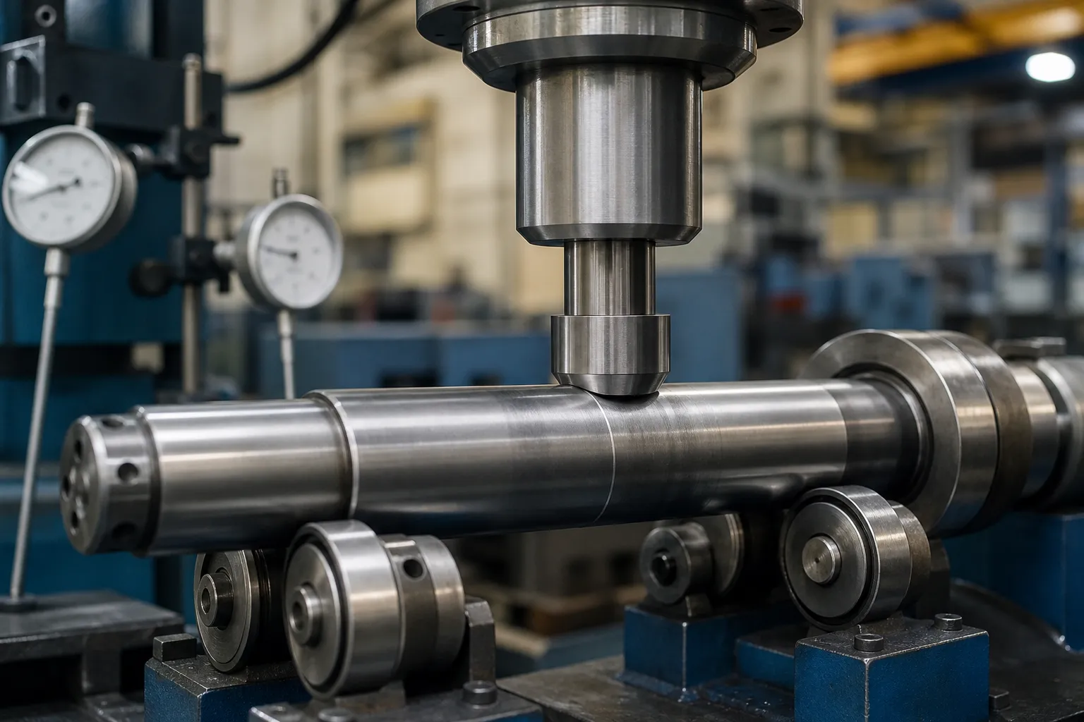
Тріщини, Surface Integrity, and Inspection
The single biggest technical risk in straightening high-strength aerospace material is not failing to reach the tolerance – it is what an overloaded correction can do. Excessive bending stress can initiate or grow cracks, and a part that measures perfectly straight after an aggressive press is not acceptable if its integrity has been compromised. This is why capable straightening processes run inside computed load limits, and why crack detection belongs in the conversation around any straightening step on flight hardware; наша стаття про виявлення тріщин під час автоматичного рихтування covers the process-signature side of this discipline.
Surface condition is the second concern. Шийки підшипників, діаметри ущільнень, and plated surfaces must survive the straightening operation without marks, brinelling, or coating damage, which constrains support and tooling contact – the same class of problems discussed in our page on вибір точки вимірювання для ступінчастих валів, where what the machine touches and what the drawing cares about have to stay aligned.
Specifying and Qualifying the Process
When aerospace suppliers bring straightening in-house or vet an outside service, the practical specification questions are:
- Definition of good. Straightness over full length, runout at named diameters, or both – stated exactly as the drawing states them. Наш огляд straightness vs runout vs TIR helps keep the definitions straight in procurement documents.
- Proof with your parts. Capability demonstrated on representative production parts, not on demonstration pieces. Structured sample testing of the kind described in випробування зразків випрямлення та прийняття is the norm, extended with first-article inspection for the production launch.
- Records. Per-part initial measurement, press iterations, остаточне вимірювання, and disposition, exportable into the quality system and retained for traceability.
- Dispositions for the rejects. What happens to a part that will not come into tolerance – rework limit, брухт, or engineering review – decided in advance. Setting these limits is the same discipline described in NOK сортування та межі доробки в лінії правки.
- Machine capability, not just machine function. For tight work, ask how the machine’s own measurement is validated. Gage studies of the kind covered in Гейдж Р&R для випрямлення ліній separate real part variation from measurement variation – a distinction that matters enormously when the acceptance band is narrow and the material is expensive.
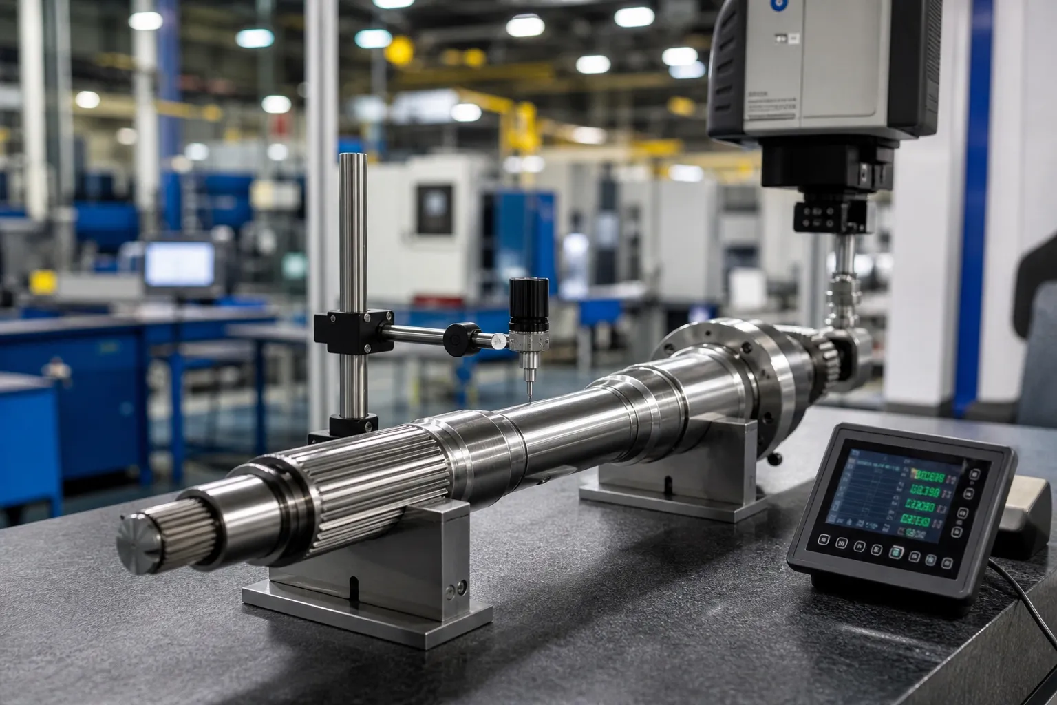
A note on the images in this article: they are engineering concept illustrations created for this article, not photographs of a specific customer line, machine model, or installation, and they are intended to support the process discussion only.
Часті запитання
Can nickel-base superalloy shafts be press straightened?
так, within the limits of the material and the drawing. High yield strength means higher forces and a stronger springback response, so the machine, оснащення, and correction strategy have to be sized for the material. Whether press straightening or a thermal or peening method is appropriate for a specific flight part is a process-engineering decision made against the material specification.
Does straightening affect fatigue life?
Any plastic deformation changes the local stress state, and that is exactly why aerospace straightening is controlled rather than improvised. Controlled correction inside computed load limits, with surface integrity protected by proper tooling, is standard practice across the industry; uncontrolled over-pressing is not acceptable anywhere. Where fatigue is the governing concern, the correction method and any subsequent inspection are agreed with the responsible engineer.
Is straightening allowed under AS9100?
AS9100 does not prohibit straightening; it requires that it be a defined, controlled process. That means documented parameters, qualified equipment and personnel where applicable, traceable records, and acceptance against the drawing or approved repair limits. Many aerospace suppliers run straightening as an in-house controlled process for exactly this reason.
Should straightening happen before or after final grinding?
The common sequence corrects geometry after heat treatment and before finish grinding, so the grinding operation cleans up surface effects and holds final diameters on a part that is already substantially straight. The exact position depends on how much grinding stock the plan carries and how the tolerances are distributed, and it should be agreed between machining and straightening process owners.
Our volumes are low – does an automatic straightening machine still make sense?
Automation in aerospace is usually justified by repeatability and records rather than by cycle time. A machine that measures, виправляє, повторні заходи, and documents every part removes operator-to-operator variation from a controlled process and produces the traceability the quality system wants. Where part variety is wide and volumes are genuinely small, the decision usually comes down to changeover time and recipe handling rather than automation level – a semiautomatic machine with quick-change tooling can be the right answer.
Висновок
Aerospace shaft straightening is precision correction work under full quality-system discipline. The parts are expensive, the materials are unforgiving, and the evidence requirements are strict – but the underlying method is measurement-driven, controlled plastic deformation with protected surfaces and verified results. Suppliers who define the process up front, demonstrate it on their own parts, and demand per-part records end up with a straightening step that auditors and customers can both live with. If your operation produces aerospace shafts, шпильки, or actuation components and you are evaluating how to bring correction in-house or under better control, start the conversation with your part spectrum, матеріалів, and tolerances.