
Beton ve darbeli matkap uçları, uzun çelik gövdeyi helisel kanallarla birleştirir, karbür kesme yapısı ve oluklu veya profilli tahrik sapı. Bu özellikler iş parçasını düz yuvarlak çubuktan çok farklı kılar. Bir ölçüm probu, gerçek gövde ekseni yerine kanalı takip edebilir, yanlış yerleştirilmiş bir destek veya pres karbür bağlantıya zarar verebilir, kesme kafası, oluk kenarı veya SDS bağlantısı.
Bu nedenle bir beton matkap ucu düzeltme çözümü, tam uç ailesi ve üretim aşamasına göre tasarlanmalıdır.. Çizimle tanımlanan bir özelliği ölçmelidir, yalnızca onaylı çelik bölgeleri düzeltin ve düzeltmeden sonra hem geometriyi hem de durumu doğrulayın.
Beton Matkap Uçları Tek Bir İş Parçası Değildir
Resmi ürün çeşitleri önemli yapısal farklılıklar göstermektedir. Bosch, iki kesicili tungsten karbür plakaları listeliyor, dört kesicili tam karbür başlıklar, iki- ve dört flüt gövdeleri, özel kaynaklı uç bağlantıları ve SDS Plus sapları. Hilti, yekpare karbür çoklu kesici başlıkları ve dörtlü helisleri listeliyor. DEWALT karbür uçlarını listeliyor, açık kafalı tasarımlar ve uzatılmış dört kanallı gövdeler.

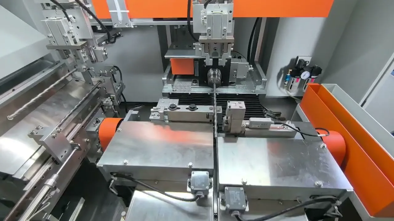
Görüntü, projenin elektrikli çekiçli matkap ucu videosundan gerçek bir küçük resim çerçevesidir. Yivli bir matkap ucunu doğrular, tutma istasyonu ve düzeltme mekanizması. Bit malzemesi oluşturmaz, boyutlar, doğruluk veya döngü süresi.
| İş parçası özelliği | Düzeltme sonucu |
|---|---|
| Lehimli/kaynaklı karbür plaka | Bağlantı noktası ve karbür normalde pres/destek bölgesinin dışında kalmalıdır |
| Tam karbür çoklu kesici kafa | Daha yüksek değerli kırılgan kafa, kontrollü kullanım ve darbe koruması gerektirir |
| İki- veya dört kanallı sarmal | Eksenel ve açısal konumla temas ölçümü değişiklikleri |
| Azaltılmış çekirdek veya değişken kanal derinliği | Bükülme sertliği çalışma uzunluğu boyunca değişir |
| SDS Plus/Max veya diğer tahrik şaftı | Yuvalar ve sürücü özellikleri düz silindirik bir veri değildir |
| Yuvarlak, düz veya özel ayna ucu | Varyanta özel konumlayıcı ve salgı tanımı gerektirir |
| Sertleştirilmiş veya yüzeyi işlenmiş çelik gövde | Geri yaylanmayı değiştirir, işaretleme ve çatlak riski |
Üretim Aşamasını Belirleyin
| Sahne | Potansiyel amaç | Ana kısıtlama |
|---|---|---|
| Oluklamadan önce çelik boş | İşleme/şekillendirme öncesinde düz bir referans oluşturun | Son flüt/kafa ilişkisi henüz mevcut değil |
| Flüt oluşturulduktan sonra | Karbürü takmadan önce gövde çarpıklığını düzeltin | Periyodik sarmal profil aracılığıyla ölçüm yapın |
| Isıl işlemden sonra | Doğru termal bozulma | Sertlik, geri esneme ve çatlak limitlerinin doğrulanması gerekir |
| Karbür bağlandıktan sonra | Montaj veya birleştirme distorsiyonunu düzeltin | Karbür ve lehimli/kaynaklı bağlantıyı koruyun |
| Taşlama/kaplama sonrasında | Nihai geometriyle tanışın | Çok sıkı yüzey ve son teknoloji koruma |
En güvenli ve en yetenekli aşama otomatik olarak son aşama değildir. Bir işlem daha önceki bir düzeltmeden sonra tekrar tekrar bitleri büküyorsa, proje bu yukarı yöndeki nedeni ele almalı veya düzeltme işlemini daha sonraki uygun bir aşamaya taşımalıdır.
Gerekli Proje Girdileri
| Giriş | Gerekli ayrıntı |
|---|---|
| Çizim | Revizyon, kontrollü özellik, tarih ve toleranslar |
| Bit ailesi | Çap, toplam/çalışma uzunluğu, flüt sayısı ve çekirdek profili |
| Kesme kafası | Karbür plaka/tam kafa, kesici sayısı, ortak tip ve yasak bölgeler |
| İncik | SDS Plus/Maks, yuvarlak, altıgen veya özel bağlantı geometrisi |
| Malzeme rotası | Çelik kalitesi, sertleşme, karbür bağlama ve kaplama sırası |
| Gelen viraj | Büyüklük, Temsili partilerden düzlem ve eksenel dağılım |
| Son muayene | Doğrusallık/saldırı/profil yöntemi, ölçer, yönlendirme ve çözünürlük |
| Üretim kapsamı | Varyantlar, çıktı hedefi, yükleniyor, geçiş ve izlenebilirlik |
Önceki sayfalarda doğrulanmış boyut yoktu, sertlik, doğruluk veya döngü verileri. Videodan hiçbir şey çıkarılmamalı.
Doğruluk, Salgı ve Uç Hizalaması Farklı
| karakteristik | Neyi değerlendirir | Tanım gerekli |
|---|---|---|
| Vücut düzlüğü | Seçilen bir yüzey elemanının veya türetilmiş gövde ekseninin formu | Kontrollü uzunluk ve flüte duyarlı değerlendirme yöntemi |
| Radyal salgı | Bir veri etrafında dönerken yüzey değişimi | Datum özellikleri, prob/optik konum ve açısal örnekleme |
| Uçtan sapa hizalama | Kesme kafası ile tahrik-şaft ekseni arasındaki ilişki | Kafa özelliği, sap verisi ve kabul bölgesi |
| Flüt profili/kurşun | Helisel özellik geometrisi | Eksenel aralık, açısal referans ve profil yöntemi |
| Fonksiyonel rotasyon | Onaylı bir ayna veya test milindeki davranış | Chuck, ekleme derinliği, hız ve ölçülen konum |
ISO 1101 geometrik spesifikasyon dilini tanımlar, ancak müşteri çizimi gerçek toleranslı özelliği tanımlamalıdır. Bir makine, bu seçim ve veri açık bir şekilde ortaya çıkana kadar "doğruluk veya salgıyı garanti edemez".
Flüt Farkında Ölçüm Önemlidir
Dönen bir sarmala temas eden bir temas probu olukla birlikte yükselir ve düşer. Bu periyodik sinyal, değerlendirilen merkez hattı bükülmesinden çok daha büyük olabilir. SDS yuvaları ve daireleri sürücü ucunda aynı sorunu yaratıyor.
Ölçüm konsepti aşağıdakilerden birini veya birkaçını kullanmalıdır:
- çizim bir tane sağladığında tanımlanmış düzgün silindirik bir alan;
- Aynı flüt/arazi ilişkisini ölçmek için kontrollü açısal indeksleme;
- çoklu optik silüetler ve kalibre edilmiş merkez çizgisi/profil modeli;
- Onaylanmış eksenel konumlarda temassız sensör;
- fonksiyonel veriyi temsil eden bir ana ayna veya merkezler;
- bilinen referans parçalara göre doğrulanmış filtreleme, yalnızca grafiğin düzgün görünmesi için seçilmemiştir.
Prob kuvveti, destek konumu ve sıkıştırma kuvveti, ince matkap gövdesinin ölçümün kendisi tarafından bükülmemesini sağlayacak kadar düşük olmalıdır.
Önerilen Kapalı Döngü Doğrultma İşlemi
1. Bit ailesini tanımlayın
Operatör veya otomasyon uç çapını doğrular, uzunluk, flüt/kafa tasarımı ve sap tipi. Tarif konum belirleyiciyi seçer, destekler, onaylı ölçüm konumları, düzeltme sınırları ve yasak bölgeler.
2. Kesici kenarlara temas etmeden yükleme yapın
Tepsi, Magazin veya besleyici takımları, karbür ile karbürün çarpışmasına gerek kalmadan bir parça sunar. Kafa ve kanal kenarları sert duruşlardan uzak kalır. Otomatik besleme gerçek uzunlukta denenmelidir, yüzey, yağ ve dolaşma koşulları.
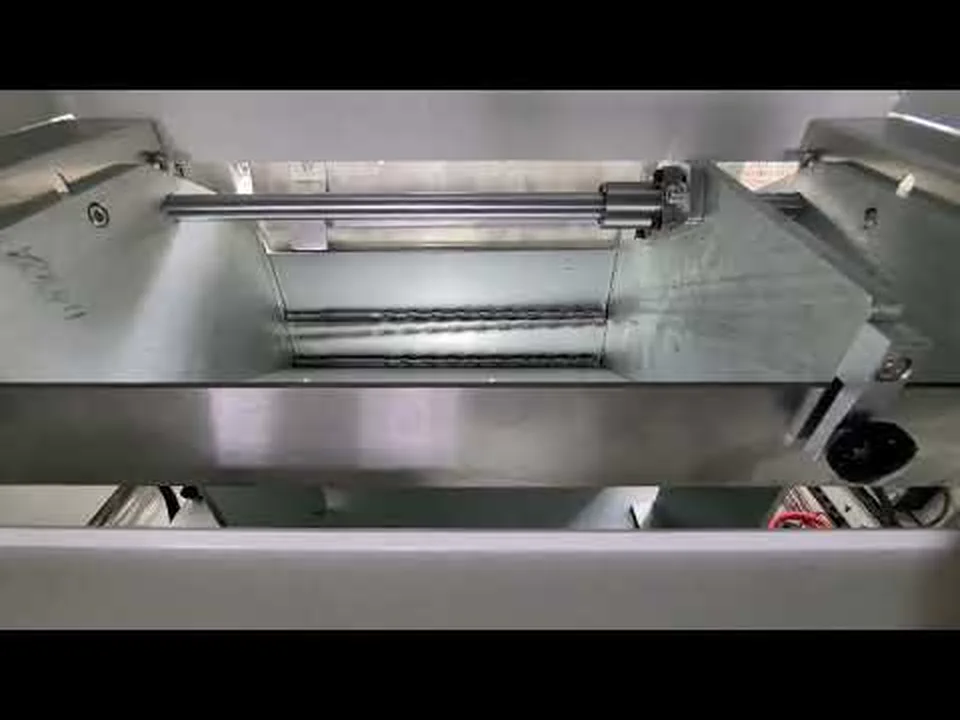
Bu kare, halka açık doğru beton-bit makinesi videosundan geliyor ve besleme alanını gösteriyor. Gözetimsiz besleme performansını kanıtlamaz, kapasite veya değişim süresi.
3. Veriyi oluşturun
Uç, onaylı bir pürüzsüz sap bölgesi tarafından tutulur, merkezler veya işlevsel bir arayüz. SDS yuvaları konum belirleyiciyi etkilediklerinde indekslenir. Fikstür, ucu yapay olarak düz bir duruma sıkıştırmamalıdır.
4. Gelen geometriyi ölçün
Temaslı veya temassız sensörler yalnızca doğrulanmış konumlarda ve yönlerde veri toplar. Kontrolör tekrarlanabilir kanal/profil imzasını büküm karakteristiğinden ayırır ve gelen sonucu saklar.
5. Destekleri ve düzeltme noktasını seçin
Destekler ve onaylanmış çelik gövde bölgelerindeki baskı hareketi. Kesme kafası, karbür eklem, flüt kenarı, azaltılmış çekirdek, Çizim ve numune testi teması açıkça onaylamadığı sürece ısıl işlem geçişi ve SDS özellikleri hariç tutulur.
6. Sınırlı nokta düzeltmesi uygula
Pres kontrollü bir yer değiştirme veya kuvvet uygular. Sertleştirilmiş, ince ve yivli uçlar, maksimum kuvvet/strok ve yineleme limitleriyle aşamalı düzeltme gerektirir. Ağır bir düzeltme genel bir strateji değildir.
7. Aynı veriyi kullanarak yeniden ölçün
Parça, veri mantığını değiştirmeden yeniden ölçülür. Yalnızca doğrulanan pencerede başka bir düzeltmeye izin verilir. Aşırı gelen bükülmeye sahip parçalar, kararsız okumalar veya beklenmeyen geri esnemeler incelenmek üzere ayrılır.
8. Durumu ve işlevi doğrulayın
Son kontroller geometriyi içerebilir, karbür/bağlantı muayenesi, flüt ve kaplama durumu, çatlak kontrolü ve fonksiyonel ayna dönüşü. Gerekli set üretim aşamasını ve kalite planını takip eder.
Gerçek Beton Matkap Ucu Doğrultma Videosu
Aşağıdaki videonun başlığı Automatic Straightening Machine for concrete bit Doğrultma Makinesi kanalında. Beslemeli bir beton/döner darbeli matkap ucu hücresini gösterir, tutma ve düzeltme ekipmanı. Belirli bir doğruluğu kanıtlamaz, çıktı, getiri veya müşteri sonucu.
Yüzey, Karbür ve Bağlantı Koruması
| Risk | Kontrol |
|---|---|
| Karbür uç elleçleme nedeniyle kırıldı | Parçaları ayırın ve kafa boşluğu takımını kullanın |
| Lehimli/kaynaklı bağlantı aşırı yüklenmiş | Bir dışlama mesafesi ve maksimum düzeltme momenti tanımlayın |
| Flüt kenarı çentikli | Profil uyumlu destekleri ve onaylı temas bölgelerini kullanın |
| Sertleşmiş gövde çatlakları | Gelen bükülmeyi ve düzeltmeyi sınırlayın; gerekli çatlak incelemesini ekleyin |
| Yanlış veri olarak kullanılan SDS yuvası | Çizim onaylı yüzeylere veya işlevsel ayna arayüzüne yerleştirin |
| Prob sarmalı takip ediyor | Dizine alınmış/profile duyarlı veya temassız ölçüm kullanın |
| Kaplama veya bitiş işaretli | İletişim malzemesini doğrulayın, basınç ve muayene standardı |
| Bit fikstürden çıkıyor | Sıkıştırmayı kontrol edin ve düzeltme alanını koruyun |
Nokta Düzeltme veya Rulo Doğrultma?
| Karar faktörü | Nokta düzeltme şu durumlarda tercih edilebilir: | Silindir doğrultma şu durumlarda değerlendirilebilir: |
|---|---|---|
| Büküm dağılımı | Yüksek noktalar ayrı ayrı ölçülebilir | Eğrilik yeterince düzgün bir gövde boyunca dağıtılır |
| Geometri | KAFA, yivler ve sap seçici temas gerektirir | Sürekli bir silindir temas yolu mevcuttur |
| Ölçüm | Kapalı döngü yeniden ölçüme ihtiyaç var | Hat içi ölçümden önce/sonra sonucu doğrulayabilir |
| Yüzey | Yerel korumalı temas kabul edilebilir | Sürekli silindir temasına izin verilir |
| Ürün karışımı | Çoklu varyantlar özel tariflere/aletlere ihtiyaç duyar | Kararlı yüksek hacimli aileler doğrulanmış bir rulo düzenini paylaşıyor |
Karbür başlık tüm düzleştirme işlemlerini otomatik olarak engellemez, ancak güvenli temas ve düzeltme penceresini daraltır. Süreç örneklerden ve çizimden seçilir, evrensel bir slogandan değil.
Örnek Test ve Kabul Planı
Temsili örnekler
- en küçük gövde/çekirdek ve en uzun esnek model;
- her flüt sayısı, karbür kafalı tasarım ve sap ailesi;
- each heat-treatment and coating condition;
- gerçek gelen bükülme dağılımı boyunca örnekler;
- multiple production batches where joining distortion or springback can vary;
- boundary parts near the intended correction limit.
Gerekli kanıt
| Kayıt | Kabul kanıtı |
|---|---|
| Parça kimliği | Çizim revizyonu, değişken, material route and batch |
| Gelen geometri | Veri, yönlendirme, positions and measured values |
| Takımlama | Locator, destekler, press and prohibited contact zones |
| Düzeltme geçmişi | Konum, kuvvet/yer değiştirme ve yineleme sayısı |
| Son geometri | Same machine setup plus customer-gauge correlation |
| Head/joint/flute condition | Agreed visual, magnified or NDT result |
| Functional result | Chuck rotation or downstream test when required |
| Üretim denemesi | Ölçülen döngü, feeding stability, changeover and availability |
Automation and Changeover
| Seviye | Tipik kapsam |
|---|---|
| Manuel yükleme | Operatör yüklemeleri; makine önlemleri, düzeltir ve doğrular |
| Magazine/tray | Controlled presentation for a stable bit family |
| Otomatik hücre | Besleme, Tanılama, ölçüm, correction and sorting |
| İzlenebilir hücre | Part/lot, yemek tarifi, ölçüm ve düzeltme kayıtları |
Changing diameter or length may require supports, chuck, sensor position and press-tool changes. Changing from a two-cutter SDS Plus bit to a full-carbide four-cutter or another shank family is not only a PLC recipe change.
Evrensel Bir Vaat Ne Değildir?
Çizim incelemesinden ve örnek doğrulamadan önce, bu çözüm vaat etmiyor:
- one tolerance, cycle time or yield for every concrete drill bit;
- that straightness and runout are interchangeable;
- gelen her bükülme büyüklüğünün düzeltilmesi;
- zero damage to carbide, joint, flüt, coating or shank;
- automatic feeding for every length and head style;
- that PLC control eliminates software, tooling or changeover work;
- a fixed labour saving or production improvement;
- safe repair of used, impact-damaged or cracked drill bits.
İlgili Uygulamalar
Gözden geçirmek Bağlantı Elemanı ve Takım Doğrultma Çözümleri ve Bilyalı Saplama Doğrultma Makinası for adjacent tooling and controlled-correction concepts. Medical and surgical drills remain a separate content family because their workpiece, yüzey, regulatory and measurement requirements differ.
Teklif İçin Gönderilecek Bilgiler
To turn this concrete drill bit guidance into a purchase decision, ile başla düzleştirici seçim kılavuzu ve sayıları basınç testiyle test edin doğrultma makinesi için bütçe resmi.
Çizimi ve revizyonu gönderin, temsili örnekler, diameter/length/flute/head/shank range, material and hardening route, carbide attachment method, imalat aşaması, gelen viraj dağıtımı, Nihai karakteristik ve veri, müşteri inceleme kurulumu, yasaklı temas bölgeleri, head/joint/flute inspection rules, çıktı hedefi ve yükleme tercihi.
StraighteningTech ile iletişime geçin numune bazlı beton matkap ucu düzeltme çalışması için. Ölçüm modelini tanımlayacağız, korumalı takımlar, düzeltme sınırları, Gerçek bit ailesi için otomasyon kapsamı ve kabul kanıtı.
Sıkça Sorulan Sorular
Prob doğrudan sarmal kanal üzerinde ölçüm yapabilir mi??
Yalnızca o profil için tasarlanmış bir yöntemle. Dönen bir temas probu aksi halde sarmalı takip edecek ve periyodik profil değişikliğini merkez hattı bükülmesiyle karıştırabilir. Kontrollü indekslemeyi kullan, doğrulanmış bir profil modeli, pürüzsüz bir arazi veya uygun temassız ölçüm.
Karbür başlık destek veya baskı noktası olarak kullanılabilir mi??
Varsayılan olarak değil. Karbür ve lehimli/kaynaklı bağlantısı hassas işlevsel bölgelerdir. Takım normalde kafa ve bağlantıdan bir dışlama mesafesi ile onaylanmış çelik gövde alanlarına etki eder.
SDS sapı güvenilir bir dönüş verisi midir??
Yalnızca çizim veya işlevsel test bunu bu şekilde tanımlıyorsa ve konumlayıcı, onaylanmış ayna arayüzünü yeniden üretiyorsa. Yuvaları ve sürücü özellikleri tam bir silindirik yüzeye eşdeğer değildir.
Uç, karbür eklemeden önce veya sonra düzeltilmeli mi??
Bu, çarpıtmanın nerede ortaya çıktığına ve hangi nihai ilişkinin kontrol edildiğine bağlıdır.. Daha erken düzleştirme daha güvenli temas sağlar; daha sonra yapılan düzleştirme, birleştirme veya ısıl işlem çarpıklığını düzeltebilir ancak daha sıkı koruma ve düzeltme sınırları gerektirir.
Bir tarif iki tarifi kapsayabilir mi?- ve dört kesici uç?
Otomatik olarak değil. Kafa boşluğu, flüt imzası, sertlik, veri, destek ve sensör konumları farklı olabilir. Doğrulanmış her ailenin doğru alet ve tarif kombinasyonuna ihtiyacı vardır.
Teknik Referans Sınırı
- Bosch SDS plus-1: https://www.bosch-professional.com/mz/en/sds-plus-1-hammer-drill-bits-2868938-ocs-ac/
- Bosch EXPERT SDS plus-7X: https://www.bosch-professional.com/gb/en/expert-sds-plus-7x-hammer-drill-bit-2867204-ocs-ac/
- Bosch SDS plus-3: https://www.bosch-professional.com/in/en/sds-plus-3-hammer-drill-bits-2867846-ocs-ac/
- Hilti TE-CX: https://www.hilti.com/c/CLS_POWER_TOOL_INSERT_7126/CLS_CONCRETE_MASONRY_DRILL_BITS_7126/r4429
- DEWALT SDS Plus Duvar Matkap Ucu: https://www.dewalt.com/en-us/product/dw5443/916-x-10-x-12-rock-carbide-sds-plus-drill-bit
- MAE İş Parçaları ve Uygulamaları: https://mae-group.com/en/workpieces-applications/
- ISO 1101:2017: https://www.iso.org/standard/66777.html
Bu referanslar matkap ucu yapı çeşitliliğini ve genel geometrik/doğrultma ilkelerini destekler. Başka bir tedarikçinin performansının StraighteningTech konfigürasyonu için geçerli olduğunu kanıtlamazlar.