
Oceľové hriadele a časti valcového tyčového typu môžu po tepelnom spracovaní vyvinúť oblúkové a radiálne hádzanie, sústruženie, brúsenie, skladovanie alebo manipulácia. Keď obrobok obsahuje niekoľko priemerov, problém s korekciou nie je jednoducho „vyrovnať tyč“: stroj musí otáčať diel v dohodnutom nulovom bode, merať iba schválené priemery, vyberte jeden alebo viac bezpečných korekčných bodov a chráňte špecifikovanú povrchovú úpravu.
Toto navrhované riešenie je založené na 25 oceľ alebo ekvivalentný materiál, tvrdosť HB 241–302, dĺžky od 183 do 720 mm a meracie priemery od 14 do 23.5 mm. Zákazník zaznamená maximálny prichádzajúci nábeh z 0.5 mm a cieľové hádzanie vonkajšieho priemeru 0.2 mm, s 1–5 vyrovnávacími bodmi. Toto sú vstupy projektu a musia byť v korelácii s výkresom, dátum, meracích pozícií a reprezentatívnych skúšok vzoriek predtým, ako sa stanú zárukami akceptácie stroja. The underlying closed-loop principle is explained in ako funguje automatické vyrovnávanie hriadeľa.
Oceľový hriadeľ / Požiadavka na lištu a projekt
Údaje zákazníka rozlišujú merné a nemerné priemery, čo naznačuje skôr problém s kontrolou rotujúceho hriadeľa/hádzania ako jednoduchú kontrolu pravítka po celej dĺžke. Konečný výkres musí identifikovať funkčný základ, presné meracie priemery a funkcie, ktoré možno použiť na podporu, otáčanie a lisovanie.
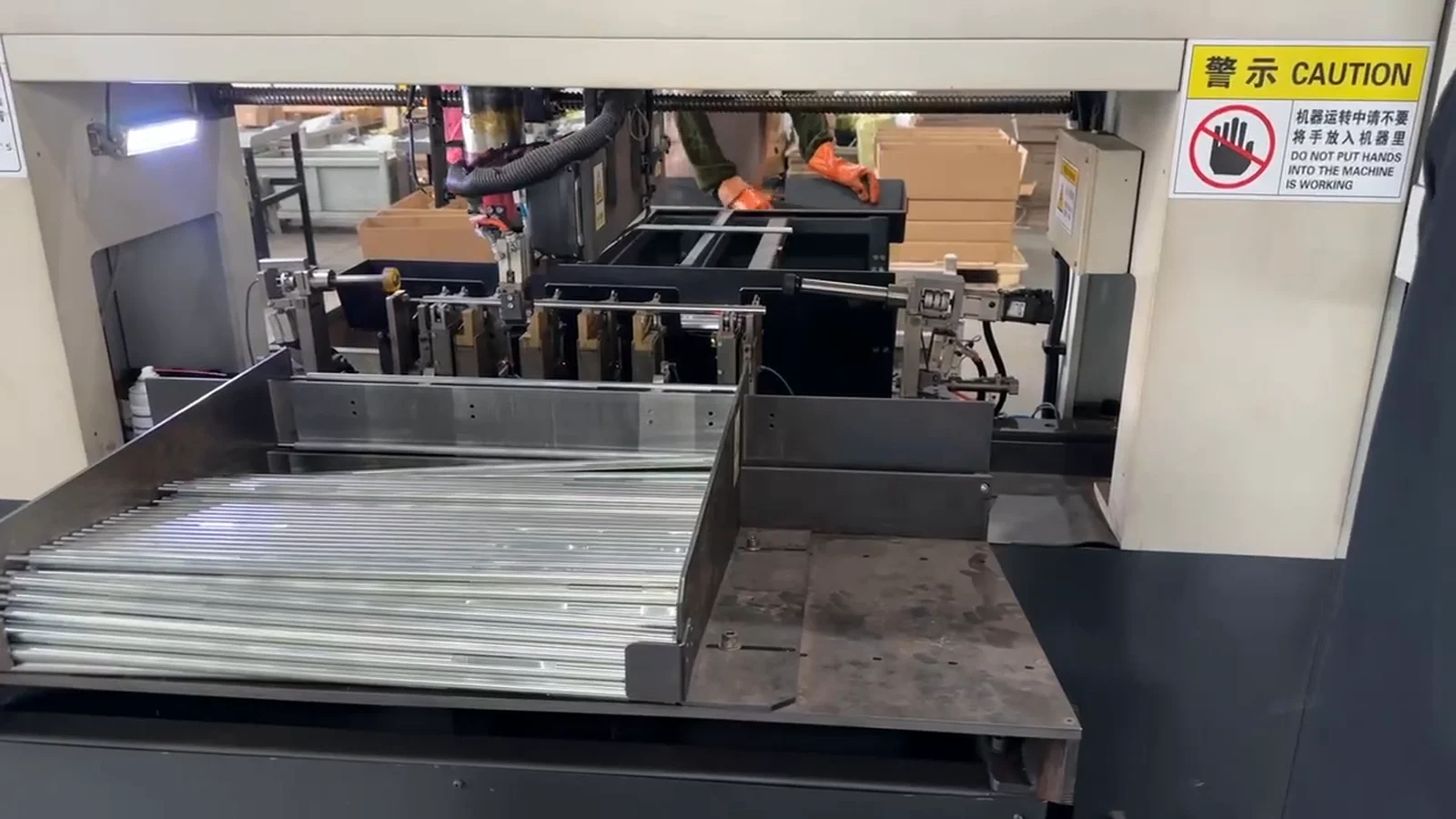
Verejné projektové video má názov stroj na vyrovnávanie rúr a zobrazuje dávku valcového materiálu vstupujúceho do viacbodovej meracej/lisovacej stanice. Pretože nie je jasne viditeľná žiadna čelná plocha, zábery nepreukazujú, či sú diely plné tyče alebo duté rúry, ani nedokazuje, že sú uvedené 25 oceľové obrobky. Tento článok preto používa zákaznícku špecifikáciu na definovanie návrhu oceľového hriadeľa/tyče a video používa iba ako dôkaz všeobecnej koncepcie automatizácie valcového skladu.
| Projektová položka | Zákaznícky vstup / Stav |
|---|---|
| Obrobok | Oceľový hriadeľ / časť valcového tyčového typu; konečná žiadosť bude potvrdená |
| Materiál | 25 oceľ alebo ekvivalent; vyžaduje sa presný štandard a certifikát |
| Drsnosť povrchu | Ra 1.25 μm |
| Tvrdosť | HB 241–302 |
| Maximálny prichádzajúci beh | 0.5 mm vstup zákazníka |
| Target OD Runúť | 0.2 mm požiadavka zákazníka; údaj a metóda merania sa majú potvrdiť |
| Merací priemer | 14.0-23,5 mm |
| Iný priemer | 14.0-28,5 mm |
| Dĺžka | 183– 720 mm |
| Rovnacie polohy | 1– 5 zákazníckych vstupov; vyžaduje sa definícia meracieho/korekčného bodu |
| Navrhovaná metóda | Automatické rotačné meranie s bodovým lisovaním a úplným premeraním |
Radiálne hádzanie je definované referenčným bodom
Radiálne hádzanie je rozdiel medzi maximálnymi a minimálnymi hodnotami sondy, keď sa obrobok otáča okolo definovanej osi. Ak je hriadeľ podopretý v stredoch, dva denníky, valčeky alebo iný pár priemerov, každé nastavenie môže priniesť iný výsledok. The customer's 0.2 mm terč musí byť preto pripojený k rovnakému nulovému bodu, aký bol použitý pri výstupnej kontrole.
Rovnosť a hádzanie spolu súvisia, ale nie sú vzájomne zameniteľné. Rovný povrch môže stále vykazovať hádzanie, ak je základný bod excentrický, a zjavne prijateľné hádzanie pri jednom priemere môže skrývať ohyb v inej axiálnej polohe. Recept stroja by mal identifikovať každý požadovaný merací bod, jeho priemer, povolený kontaktný oblúk sondy a limit prijatia.
| Kontrolná položka | Povinná definícia |
|---|---|
| Dátum | centrá, vybrané čapy alebo špecifikované referenčné priemery |
| Meranie priemerov | Presné polohy v rámci uvedeného rozsahu 14–23,5 mm |
| Limit prichádzajúcich | Maximálne 0.5 hádzanie mm; potvrdiť, či to platí v každom bode |
| Konečný cieľ | 0.2 mm OD runúť; požiadavka zákazníka, zatiaľ neakceptovaný výsledok |
| Rovnacie polohy | 1–5 schválených axiálnych lisovacích zón; nie sú automaticky identické s meracími bodmi |
| Stav povrchu | Ra 1.25 μm a povolené kontaktné plochy podpery/sondy/lisu |
| Záverečná kontrola | Rovnaká základná logika, rotačný spôsob a filtrovanie ako dohodnuté meradlo zákazníka |
Prečo je ťažké narovnať túto rodinu hriadeľov a tyčí
Dĺžka sa mení takmer štvornásobne a obálka priemeru zahŕňa meracie aj nemeracie úseky. A 720 mm časť pri menšom priemere je oveľa pružnejšia ako krátka časť pri najväčšom priemere. Jedno pevné rozpätie podpery alebo zdvih lisu nemôže bezpečne pokryť rodinu.
Odchýlka tvrdosti od HB 241 do 302 tiež mení pruženie a množstvo trvalej korekcie vyvolanej rovnakým zdvihom. Ra 1.25 μm povrch musí zostať bez neprijateľných škrabancov sondy, podporné značky alebo tlačové výtlačky. Ak časť obsahuje ramená, drážky, krížové otvory, vlákna alebo iné prechody, ktoré nie sú uvedené v aktuálnych údajoch, môžu vytvárať koncentrácie napätia a dodatočné zóny bez tlaku.
| Výzva pre konkrétny obrobok | Riziko | Požadovaná kontrola |
|---|---|---|
| 183Rozsah dĺžky - 720 mm | Nesprávny rozsah podpory a nestabilná odozva | Podporné pozície a recepty špecifické pre daný model |
| Meracie vs. nemeracie priemery | Sonda na nesprávnom povrchu alebo nesúlad nuly | Definícia meracieho bodu a dráha snímača založená na výkrese |
| Rozsah tvrdosti HB 241–302 | Variabilné odpruženie, riziko nadmernej korekcie alebo prasknutia | Adaptívny zdvih, konzervatívne limity a overenie šarže/vzorky |
| Ra 1.25 μm povrchu | Kontaktné značky alebo hlučné meranie | Čisté tvarované podpery, vhodná sila sondy a schválené kontaktné zóny |
| 1–5 korekčných polôh | Jedno stlačenie zmení susedné body | Meranie po celej dĺžke a overená sekvencia korekcií |
| Možné prechody sekcií | Lokálna koncentrácia stresu | Zóny bez lisovania a vhodná geometria razníka/podpory |
| Žiadosť o výmenu konkurenta | Nepodporovaná ekvivalencia alebo nárok na cenu | Referenčná hodnota rovnakej vzorky s dohodnutými kritériami prijatia |
Odporúčaná metóda vyrovnávania
Automatické vyrovnávanie bodov lisovaním je preferovanou počiatočnou metódou, pretože diel sa meria pomocou radiálneho hádzania v niekoľkých možných axiálnych miestach. Systém otáča hriadeľom, identifikuje veľkosť ohybu a smer uhla, umiestni obrobok alebo lis na schválený korekčný bod, aplikuje kontrolované prehýbanie a potom zopakuje celé meranie.
Kontinuálny valčekový vyrovnávač môže byť vhodný, ak je konečným obrobkom tyč s konštantným priemerom s rovnomerným zakrivením a požiadavkou na priepustnosť, ktorá uprednostňuje spracovanie s priebežným posuvom. Menej vhodné je, keď má dielec niekoľko priemerov, chránené hotové povrchy alebo špecifických 1–5 lisovacích zón. Ak je skutočnou časťou dutá rúrka a nie plná hriadeľ/tyč, hrúbka steny, Pred výberom metódy je potrebné pridať limity vnútorného priemeru a kolapsu/ovality. Pre 12 m through-feed bar lines, pozri vyrovnávanie valcov dlhých oceľových tyčí riešenie.
Navrhovaný proces automatického vyrovnávania
Súvisiace 16-sekundové video ukazuje valcový materiál na podávacom zásobníku a kompaktnú stanicu s viacerými podperami, meracie komponenty a vertikálna lisovacia hlava. Demonštruje koncept materiálového toku a stanice, ale neoveruje materiál obrobku, pevná/dutá konštrukcia, 0.5-do-0.2 mm výsledok, Rozsah HB, čas cyklu alebo konečná konfigurácia projektu.
| Krok | Proces | Inžiniersky účel |
|---|---|---|
| 1 | Identifikácia dielov a výber receptúry | Dĺžka zápasu, priemerov, dátum, body a limity |
| 2 | Kŕmenie a oddeľovanie | Preneste jednu valcovú časť bez poškriabania alebo dvojitého podávania |
| 3 | Umiestnenie a rotácia vzťažného bodu | Vytvorte opakovateľnú os na meranie hádzania |
| 4 | Počiatočné viacbodové meranie | Zaznamenajte prichádzajúce hádzanie pri každom požadovanom priemere |
| 5 | Overenie signálu a výpočet ohybu | Oddeľte skutočný ohyb od drsnosti, výstredné alebo rysové efekty |
| 6 | Korekčný bod a uhlové polohovanie | Zarovnajte jednu zo schválených 1–5 lisovacích zón s baranidlom |
| 7 | Kontrolované nadmerné ohýbanie | Kompenzujte spätné pruženie v rámci limitov sily/zdvihu |
| 8 | Kompletné premeranie | Po každej korekcii vyhodnoťte všetky body |
| 9 | Adaptívna korekcia alebo rozhodnutie NOK | Pokračujte iba v okne overeného procesu |
| 10 | Konečné triedenie a evidencia údajov | Oddeľte diely OK/NOK a zachovajte požadované hodnoty kvality |
Kŕmenie a kontrola modelu
Odkladacia podnos alebo zásobník môžu do stanice prezentovať valcové časti. Vodiace lišty, separátory a kontaktné materiály musia pokrývať obálku s priemerom 14–28,5 mm bez zaseknutia, zmiešanie dvoch častí alebo poškodenie Ra 1.25 μm povrchu. Zmiešané modely vyžadujú overenie receptúry prostredníctvom ID dielu, kontrola dĺžky, kontrola priemeru alebo ekvivalentná metóda poka-yoke.
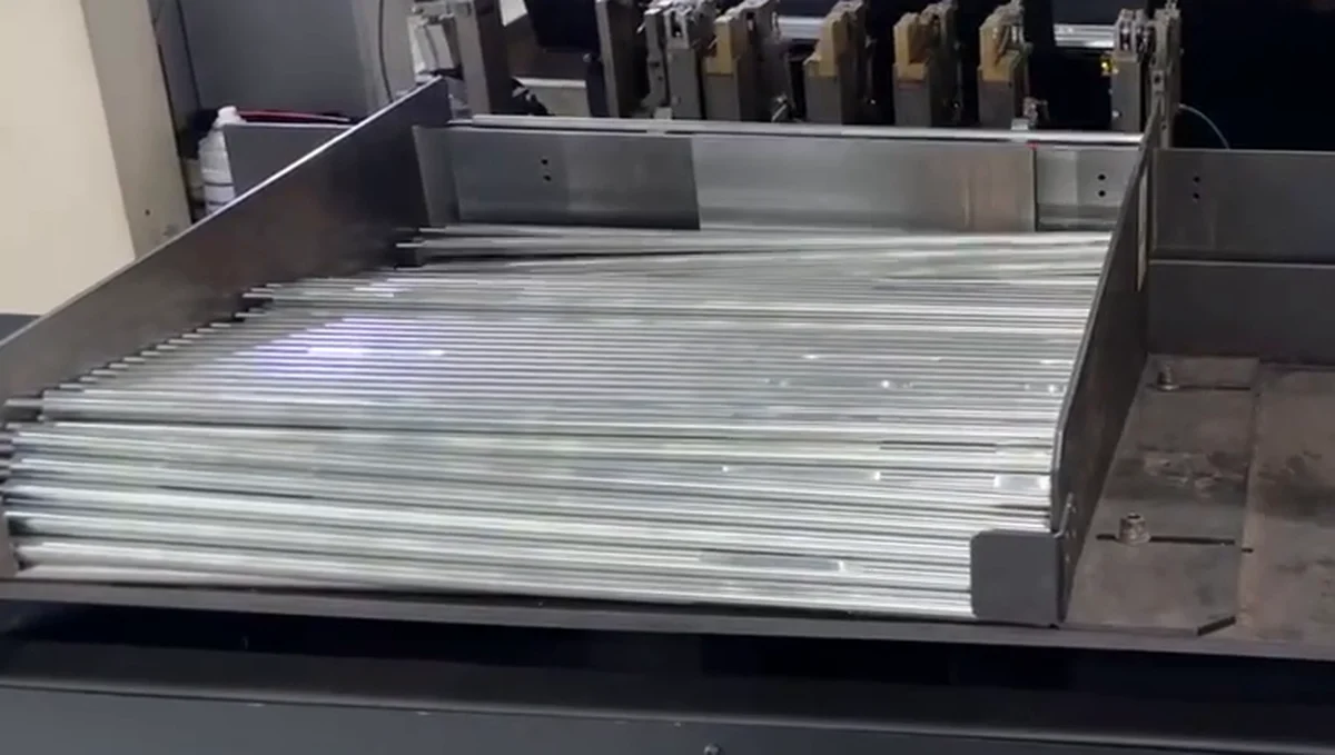
Video nedokazuje, že zobrazený zásobník pokrýva všetky uvedené dĺžky a priemery. Konečný systém podávania by sa mal overiť pomocou najkratšieho, najdlhšie, najmenší a najväčší skutočný variant.
Viacbodová rotácia a meranie
Diel sa otáča v dohodnutom dátume, zatiaľ čo kontaktné sondy alebo laserové snímače zachytávajú hádzanie pri špecifikovaných meracích priemeroch. Sila sondy, rozsah snímača a filtrovanie by sa mali zvoliť pre povrch a rýchlosť otáčania. Drsnosť povrchu, chyba kruhovitosti alebo znečistenie sa nesmie zamieňať s ohybom hriadeľa.

1–5 pozícií vyrovnávania by sa malo mapovať oddelene od meracích bodov. Sonda môže merať funkčný čap, zatiaľ čo najbezpečnejšie miesto lisu leží na susednom mieste, silnejší úsek. Riadiaca jednotka musí použiť vzťah medzi týmito bodmi namiesto toho, aby predpokladal, že každé namerané maximum možno stlačiť priamo.
Výpočet ohybu a riadené nadmerné ohýbanie
Ovládanie identifikuje dominantný vektor ohybu a vyberie sekvenciu korekcie. Prílišné ohýbanie posunie diel za požadovanú konečnú polohu, takže elastické odpruženie ho vráti bližšie k cieľu. Počiatočné limity mŕtvice by mali byť konzervatívne, najmä v blízkosti HB 302 koniec sortimentu materiálov, a spresnené z nameranej odozvy reprezentatívnych vzoriek.
Kde je k dispozícii meranie sily, sila/posunutie môže poskytnúť dodatočný limit abnormálnej odozvy. Systém by sa mal zastaviť, ak sa odpoveď podstatne líši od overeného receptu, dosiahne sa maximálny počet korekcií alebo sa časť nepodarí bezpečne zblížiť.
Kompletné premeranie a konečné rozhodnutie
Po každej tlačovej akcii, všetky požadované meracie body sa znova skontrolujú v rovnakom údaji. Lokálne zlepšenie nestačí, ak sa iný priemer pohybuje mimo toleranciu. Konečné rozhodnutie OK si vyžaduje úplný súbor špecifikovaných bodov, aby sa splnilo kritérium zákazníka.
Záznamy o kvalite môžu obsahovať ID modelu, prichádzajúci a konečný nábeh, výsledky meracích bodov, korekčné pozície/počet, verzia receptúry a konečná klasifikácia. The scope should match the customer's traceability requirement rather than adding data fields that will not be used.
Výmena existujúceho zariadenia: Použite kontrolovaný benchmark
Zákazník posudzuje alternatívu k existujúcemu rovnaciemu zariadeniu. Tvrdiť rovnaký výkon alebo pevnú dvojtretinovú cenu bez porovnania rovnakých obrobkov nie je technicky správne, metóda merania, rozsah automatizácie, nástrojov a podpory životného cyklu.
| Referenčná položka | Povinné porovnanie |
|---|---|
| Súprava obrobkov | Rovnaký najkratší/najdlhší, najmenšie/najväčšie vzorky a vzorky s najhorším ohybom |
| Dátum a meradlo | Rovnaká podpora, rotácia, sondy a výpočet akceptácie |
| Kvalita | Konečné hádzanie v každom požadovanom bode; stav povrchu a prasklín |
| Proces | Počet korekcií, čas cyklu, opakovateľnosť a sadzba NOK |
| Zmena | Nástroje, recept a čas obsluhy pre všetky modely |
| automatizácia | Kŕmenie, triedenie, sledovateľnosť a rozhrania závodu zahrnuté v oboch rozsahoch |
| Náklady na vlastníctvo | Vybavenie, náradia, inštalácia, školenia, údržbu, náhradné diely a predpoklady prestojov |
| Prijatie | Písomné kritériá FAT/SAT namiesto nepodporovaného všeobecného vyhlásenia o rovnocennosti |
Odporúčaná konfigurácia bunky
| modul | Navrhovaná požiadavka | Prečo je to potrebné |
|---|---|---|
| Koncepcia stroja | Automatická vyrovnávacia bunka lisu s rotačným bodom | Korekcia uzavretej slučky pre viacbodové hádzanie hriadeľa |
| Obal na obrobok | Dĺžka 183–720 mm; rozmer OD 14–23,5 mm; ostatné OD až 28.5 mm | Zahŕňa uvedenú skupinu projektov, podlieha kontrole kresby |
| Merací systém | Meranie viacbodového kontaktu alebo laserového hádzania | Dátum zápasu, požiadavky na povrch a dráhu snímača |
| Rotácia / Dátum | centrá, valčeky alebo podpery čapu vybrané z výkresu | Opakovateľné meranie uhlového ohybu |
| Vyrovnávacia jednotka | Jemne riadený servo/elektromechanický/hydraulický lis podľa veľkosti | Spravujte odpruženie cez HB 241–302 |
| Podporuje a Punch | Nastaviteľné, kontúrované, nástroje na ochranu povrchu | Pokryte rozsah dĺžky/priemeru a chráňte Ra 1.25 μm povrchov |
| Stratégia kontroly | Recepty, vektor ohybu, adaptívny zdvih a limity tvrdej iterácie | Opravte 1–5 bodov bez nekontrolovaného opakovaného stláčania |
| Kŕmenie | Podnos, zásobník alebo ručné nakladanie na základe overeného taktu a zmesi dielov | Prispôsobte tok výroby bez predpokladu nepodporovanej automatizácie |
| Údaje o kvalite | Výsledky pred/po a história opráv podľa potreby | Benchmarking, akceptovanie a sledovateľnosť |
| Bezpečnosť | Stráženie, zámky, alarmy preťaženia a abnormálneho merania | Chráňte operátora, diel a náradie |
Validácia projektu pred konečnou cenovou ponukou
Reprezentatívne vzorky by mali pokrývať minimálnu a maximálnu dĺžku, všetky varianty meracieho priemeru, normálne a maximálne prichádzajúce hádzanie, HB 241 a HB 302 materiálne podmienky, každá relevantná dávka tepelného spracovania a všetky prechody sekcií. Správa o skúške by mala zaznamenať údaj, každý merací bod, vstupná hodnota, opravná poloha/počet, konečná hodnota, stav povrchu a čas cyklu.
The customer's inspection gauge and the machine should be correlated before the 0.2 mm sa stáva zárukou prijatia. Ak je skutočný obrobok dutý alebo obsahuje skryté prvky, ktoré nie sú zobrazené v aktuálnych údajoch, výkres a kontrola vzorky musia pred konečným výberom stroja zrevidovať nástroje a posúdenie rizika.
Informácie potrebné pre návrh vyrovnávania oceľového hriadeľa a tyče
Uveďte konečný názov obrobku a aplikáciu, kreslenie, materiálový štandard a certifikát, stupeň tvrdosti a tepelného spracovania, všetky priemery a polohy prvkov, stredové otvory/časopisy, distribúcia prichádzajúceho výbehu, cieľ v každom bode merania, referenčná a meracia metóda, schválené podporné/tlačové zóny, požiadavka na ochranu povrchu, cieľová sadzba, ročný objem, smer zaťaženia a reprezentatívna vzorka dielov.
Tieto vstupy umožňujú tímu riešenia potvrdiť, či je dielom plný hriadeľ/tyč alebo dutá rúrka, vyberte metódu merania a vyrovnávania, veľkosť sily/zdvihu a nástrojov, a vybudovať objektívny benchmark FAT/SAT.
FAQ
Je cieľ 0.2 mm priamosť alebo radiálne hádzanie?
Aktuálny vstup to nazýva hádzanie vonkajšieho priemeru. Výkres musí potvrdiť základ, meranie polôh a spôsob otáčania. Bez týchto dôkazov by sa to nemalo prepísať ako priamosť.
Môže stroj znížiť maximálny hádzavosť z 0.5 do 0.2 mm?
To je cieľ projektu, zatiaľ neoverený výsledok. Uskutočniteľnosť závisí od dátumu, geometria, tvrdosť, rozloženie ohybov, schválené korekčné zóny a odozva na testovanie vzoriek.
Zvládne jeden stroj dĺžky od 183 do 720 mm?
potenciálne, ak podpora cestuje, meracie polohy, os lisu, systém kŕmenia a receptúry pokrývajú celý sortiment. Varianty koncového bodu musia byť zahrnuté do validácie.
Ako sa má Ra 1.25 μm povrch chránený?
Riešenie využíva čisté tvarované podpery, riadená sila sondy a ťahom schválené kontaktné/lisovacie zóny. Kontrola povrchu zostáva súčasťou akceptačného plánu vzorového testu.
Prečo je dôležité 1–5 vyrovnávacích bodov?
Naznačujú, že rôzne modely alebo profily ohybov môžu vyžadovať rôzne miesta korekcie. Stroj musí po každej korekcii premerať všetky kontrolované priemery, pretože zlepšenie jedného bodu môže zmeniť iný.
Dokazuje video, že sú pevné 25 oceľové hriadele?
Nie. Zobrazuje valcový materiál a vyrovnávaciu stanicu, ale konce a materiál nie sú identifikovateľné. The article's shaft/bar specification comes from the project data, nie z vizuálneho dohadu o videu.
Môže byť toto zariadenie prezentované ako rovnocenné s existujúcim konkurentom za fixne nižšiu cenu??
Iba po kontrolovanej referenčnej hodnote rovnakej vzorky a porovnateľnom komerčnom rozsahu. Kvalita, čas cyklu, náradia, automatizácie, náklady na služby a životný cyklus sa musia porovnať pomocou písomných kritérií prijatia.
Záver
Tento projekt oceľového hriadeľa/tyče je definovaný meraním hádzania s viacerými priemermi, 1–5 riadených korekčných polôh, HB 241–302 odpruženie a ochrana Ra 1.25 μm povrchu. Spoľahlivé riešenie musí merať celý diel na funkčnom meradle, opravte len schválené zóny a overte každý bod po každom stlačení.
For a steel shaft and bar application like this one, procurement teams usually pair the manuálna vs automatická logika výberu with the ROI puzdro pre automatické vyrovnávanie before shortlisting vendors.
Pošlite svoje kresby, certifikáty materiálu/tvrdosti, prichádzajúce údaje o vyčerpaní, 0.2 definícia prijatia mm, mix častí a vzorové informácie na preskúmanie realizovateľnosti a benchmarku. Konečný výkon by mal byť dohodnutý skôr na základe objektívnych kritérií FAT/SAT než neoverenej ekvivalencie alebo cenových vyhlásení.