
Rotujúca stopa indikátora môže obsahovať niekoľko efektov naraz. Môže odrážať os obrobku, miestne zaoblenie, valcový tvar, referenčný vzťah, podporovať sedenie, chyba prípravku, nastavenie sondy alebo prerušená funkcia. Označenie každého vysokého čítania za „ohyb“ môže viesť k nesprávnej korekčnej akcii a môže poškodiť súčiastku, ktorá skutočne potrebuje meranie alebo kontrolu obrábania..
Táto príručka vysvetľuje, ako diagnostikovať signál pred rozhodnutím o vyrovnávaní. Nezakladá systém merania StraighteningTech, tolerancie, rozlíšenie snímača, referenčný postup alebo schopnosť korekcie. Pre konečné rozhodnutia je potrebný kontrolovaný výkres a metóda zákazníckej kontroly.

*Inžiniersky koncept ilustrácie. Ukazuje, že rotačný signál môže obsahovať variáciu tvaru; nejde o výsledok merania pre zákaznícky diel ani o predpísané nastavenie kontroly.*
Pred prečítaním meradla pomenujte charakteristiku
Kruhovitosť popisuje stav tvaru prierezu. Ohyb osi opisuje priestorovú dráhu referenčnej osi. Rút je rotačné meranie vzhľadom na nastavenie nuly a môže zahŕňať viacerých prispievateľov. Koaxialita, sústrednosť a valcovitosť majú tiež odlišné definície a požiadavky na kontrolu. Výkres musí identifikovať, ktorá charakteristika riadi akceptáciu.
| Signál alebo charakteristika | Diagnostická otázka |
|---|---|
| Okrúhlosť / lobing | Mení sa miestny polomer pri otáčaní sekcie? |
| Ohyb osi | Zmení referenčná os polohu pozdĺž dĺžky? |
| Výbeh | Ktorý dátum, podpery a sondová stanica vytvárajú čítanie? |
| Koaxiálny vzťah | Sú viaceré funkcie porovnávané s definovanou spoločnou osou? |
| Signál zariadenia | Zmení výsledok opätovné usadenie alebo zmena orientácie podpery? |
Pozri priamosť hriadeľa, runout a TIR a koaxiálnosť verzus hádzanie pre súvisiacu terminológiu.
What a Rotating Trace Is Made Of
A probe reading taken while a part rotates is, mathematically, a mix of components that repeat once, twice, three times and more per revolution. Reading the mix is the core diagnostic skill. A once-per-rev component means the surface is, on average, further from the rotation axis on one side than the other — which is the signature of either an axis offset between the part’s reference geometry and the rotation axis, or of a bent axis displacing the section as a whole. A twice- or three-times-per-rev component means the section is oval or lobed: the local radius itself changes around the circumference, a form condition of the cross-section that no amount of axis correction removes. Higher-frequency content usually reflects surface texture, keyways and interrupted features, or vibration entering through the supports.
The decisive separation between the two once-per-rev causes is axial. A true bend displaces different stations by different amounts and often in different directions, so the once-per-rev component’s amplitude and phase change as the probe moves along the part. A pure eccentricity condition — centers offset, seat offset, chuck runout — produces a once-per-rev component that keeps the same phase and proportional amplitude at every station. One trace at one station cannot distinguish them; a short axial map routinely can. That is the reasoning behind the multi-station discipline above, and behind multipoint measurement arrangements that read several stations in one setup.
Where Lobing Comes From
Lobing is rarely random — it carries the fingerprint of the machining that produced the surface, which is what makes it diagnostic. Three-lobe out-of-roundness is the classic signature of parts ground on centerless machines, where the part floats between wheel, regulating wheel and blade and the geometry locks into a three-point stability condition. Even-lobe ovality traces back to opposing clamping or distortion relieved after machining — a thin sleeve released from a chuck, a part that relaxed after heat treatment. Odd lobing beyond three appears with certain workholding arrangements and with relapsing of interrupted cuts. Knowing the part’s process route therefore tells you what lobing to expect and whether an observed lobe count is a workpiece reality or an artifact of the current setup: a lobe count that changes when the part is reseated in different orientations is being generated by the setup, not the part.
Najprv skontrolujte dátum a nastavenie
Pred interpretáciou časti, overte vlastnosti stredu, čapy alebo iné referenčné povrchy, podmienka podpory, čistota, kontakt sondy, spôsob otáčania a axiálna stanica. Poškodené centrum, otrep, špinavé sedadlo, nesprávna podpera alebo kontakt sondy na prerušovanom povrchu môže vytvoriť zdanlivé hádzanie, ktoré nepredstavuje ohyb osi.
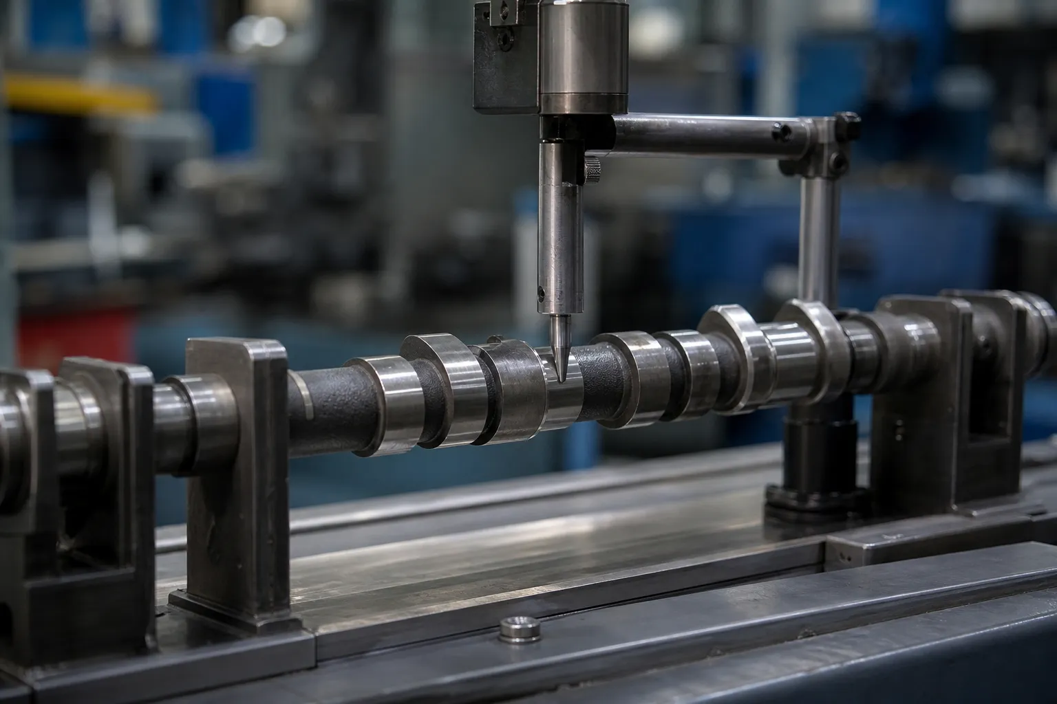
*Inžiniersky koncept ilustrácie. Ilustruje meranie žurnálu s ohľadom na funkcie; skutočné údaje, dráhy sondy a uhlové masky závisia od kontrolovaného obrobku.*
Použite kontrolu opätovného zasadenia/opakovania a porovnajte viacero staníc. Ak sa stopa po opakovaní nastavenia podstatne zmení, pred použitím korekčnej sily preskúmajte realizáciu prípravku alebo základu.
Porovnajte viacero staníc a orientácií
Ohyb osi zvyčajne vyžaduje axiálnu mapu. Miestne zaoblenie alebo lobing sa môže objaviť na jednej stanici, ale nie na inej. Jediný údaj celkového ukazovateľa v jednom bode nemôže dokázať, ktorý prispievateľ dominuje. Zaznamenajte umiestnenie staníc, orientácia, referenčná podmienka a trasovanie alebo vypočítaný výsledok požadovaný akceptačným postupom.
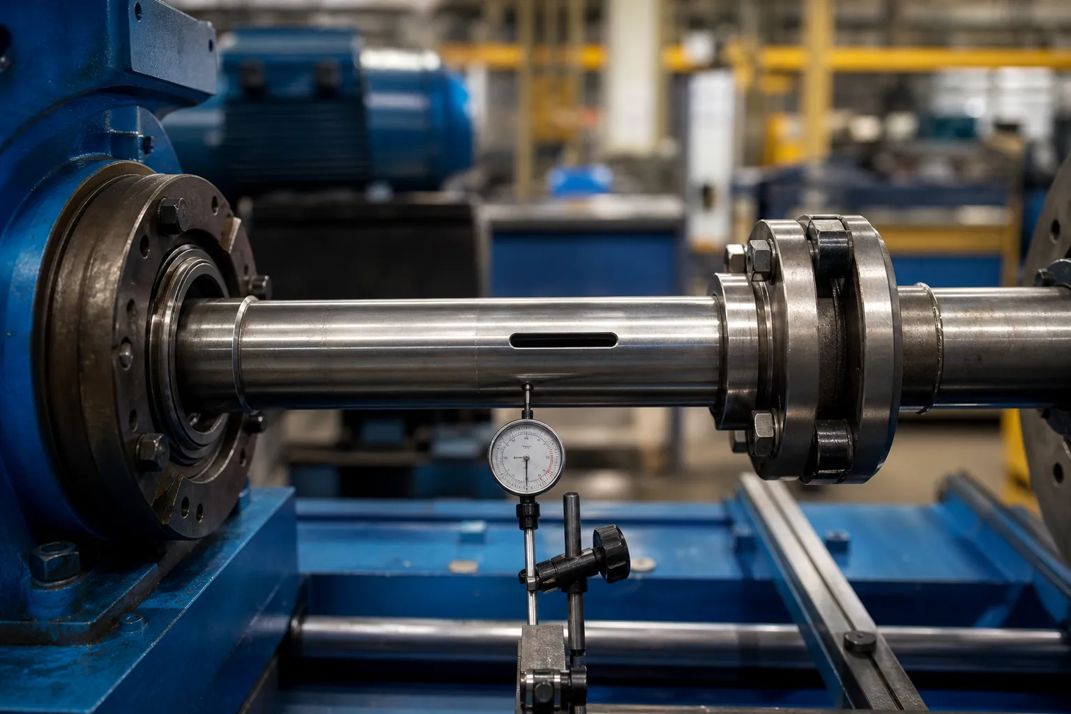
*Inžiniersky koncept ilustrácie. Predstavuje otázku rotačného merania s viacerými funkciami, nie je schváleným prípravkom alebo záverom, že pozorovaný signál je ohnutý.*
Separating Spindle Error From Part Error
On any rotating instrument, the reading contains the part’s geometry plus the rotation error of the instrument itself — spindle runout, bearing wander, support eccentricity. Precision metrology has standard separation techniques for this, and their logic is worth knowing even when the full apparatus is not available. Reversal methods measure the part in one orientation, then rotate the part exactly half a revolution relative to the fixture and measure again: part error keeps its sign in part coordinates while setup error keeps its sign in machine coordinates, so combining the two traces separates them. Multistep methods extend the same idea through a series of indexed orientations. On a production straightening machine, the practical descendants are simpler: reseating the part in a different clocking orientation and checking whether the trace rotates with the part or stays fixed in the machine tells most of the story, and comparing readings before and after swapping a support identifies which element contributes what.
These checks cost minutes and prevent the most expensive mistake on this page: correcting a bend that lives in the bench. They also make the eventual correlation to the customer gauge meaningful, because both sides of that comparison are then measuring parts rather than setups — the premise underlying meradlo R&R studies on straightening lines.
A Practical Diagnostic Sequence
The checks above assemble into a fixed order of operations that experienced lines follow before any correction decision. Po prvé, clean and inspect the seating features — centers, žurnály, support vee blocks — for damage, burrs and debris, since the cheapest explanation is always the setup. Po druhé, take a trace, reseat the part in the same orientation, and retrace: disagreement beyond the setup’s established repeatability stops the investigation at the fixture. Po tretie, reseat in a rotated orientation: a trace that follows the part is a part signal; one that stays fixed in the machine is a machine or fixture signal. Fourth, map at least three stations along the length and note how the once-per-rev component’s amplitude and phase behave: varying amplitude and rotating phase indicate bend; constant phase with proportional amplitude indicates eccentricity. Fifth, look at the lobe content in relation to the part’s machining history before believing any form conclusion. Only then choose the response — correction for confirmed axis bend within approved zones, or the alternative routes for everything else, with the released-state condition treated per zaťažené versus uvoľnené meranie.
The sequence exists because each step filters a class of false positives that would otherwise survive to the next. Skipping ahead to correction is how parts get pressed for eccentricity fixtures, ovality and chucking artifacts — damage that no later measurement undoes.
Vyberte odpoveď z diagnostiky
Ak dôkazy podporujú stav ohybu osi a existujú schválené kontaktné/podporné zóny, kandidátna dráha vyrovnávania môže byť vyhodnotená prostredníctvom vzorového testu. Ak je signál hlavne okrúhlosť, prerušená geometria, problém s dátumom, chyba upínača alebo samostatný vzťah funkcie, môže byť potrebný iný proces alebo kontrola inšpekcie. Na vyrovnanie problému s meraním nepoužívajte vyrovnávanie.
Pre riadenú lokálnu korekciu, pozri bodové lisovanie rovnanie. Pre koreláciu s metódou konečnej kontroly, see machine gauge versus customer gauge correlation.
Overte pomocou meradla zákazníka
Plán vzoriek by mal obsahovať známe/referenčné podmienky, ak sú k dispozícii, zopakujte nastavenie, viac staníc, meranie uvoľneného stavu, identifikácia dielu a príslušenstva, uchovávanie nespracovaných údajov a korelácia zákazníka. Výsledok by mal uviesť, ktorá charakteristika bola vyhodnotená a ktorá neistota alebo obmedzenia nastavenia zostávajú.
FAQ
Znamená vysoké TIR vždy, že hriadeľ je ohnutý?
Nie. TIR môže obsahovať údaj, guľatosti, príslušenstvo a ďalší prispievatelia. Najprv diagnostikujte nastavenie a viacero staníc.
Môže vyrovnávanie správne zaoblenie?
Nie ako všeobecný záver. Kruhovitosť je iná geometrická podmienka a môže vyžadovať iný proces alebo cestu kontroly.
Prečo opakovať nastavenie?
Opätovné čítanie po opätovnom usadení pomáha rozlíšiť signál obrobku od podpery, dátum alebo variácia prípravku.
What does a three-lobed trace usually indicate?
Most often, a surface produced by centerless grinding, where the three-point contact of wheel, regulating wheel and blade locks the section into a three-lobe form condition. It is a cross-sectional form issue, not an axis issue, and it should be verified against the part’s machining history before any response is chosen.
How can I tell eccentricity from bend with one probe?
Move the probe along the part and watch the once-per-rev component. Bend shows varying amplitude and shifting phase between stations; eccentricity keeps the same phase and proportional amplitude everywhere. If the probe cannot move, mapping several stations with a moved setup achieves the same separation at the cost of reseating discipline.
Does reseating the part in a different orientation really separate machine error?
áno, in its simplest form. Part error rotates with the part; machine and fixture error stay fixed in machine coordinates. Comparing traces at two clockings shows which class dominates the reading. Formal reversal and multistep methods refine the same principle when numbers, not just classification, are required.