
Um rotor de motor de lama é uma das peças de endireitamento mais exigentes na fabricação de campos petrolíferos: um sólido, eixo de aço temperado com vários metros de comprimento e apenas alguns centímetros de diâmetro, carrying a precision multi-lobe helical profile along its entire length. That helix meshes with an elastomer stator to form the power section of a positive displacement motor (PDM), and the sealing line between rotor lobes and stator only works if the rotor’s centerline is straight. A bowed rotor wears the stator, loses pressure and torque, and kills the downhole motor’s life — which is why the rotor repair and remanufacture ecosystem (hard-chrome and tungsten-carbide recoating shops, profile grinding, and dedicated rotor straightening machines) exists as its own industrial niche.
Search evidence for the rotor straightening market is concrete: European builders offer hydraulic NC rotor straightening machines built specifically for power-section and PCP rotors, with press capacities reported in the 100-400 kN class and part lengths up to fourteen meters; coating and plating contractors advertise rotor repair flows that include straightening; and rotor manufacturers describe hobbing, polishing and plating sequences where geometry control between stages is critical. Related searches even carry purchase intent (“best”, “price”). This is a real equipment and process problem — and a specialized one.
Five questions frame a mud motor rotor straightening solution:
- Is the rotor entering straightening at OEM stage (após tratamento térmico, before or after profile machining, before coating) or in remanufacturing (stripped, cleaned, awaiting re-coating)?
- What is the lobe configuration (por exemplo, multi-lobe profiles such as 5:6, 7:8), the across-crest dimension, and the total length?
- O desvio é um arco da linha central, a twist of the helix, or local bending from downhole service in a bent housing?
- Which surfaces may take press contact — and how do supports and ram feet engage a helical profile without brinishing lobe crests?
- What straightness band does the power section require, and how will it be measured on a non-round, continuously variable profile?

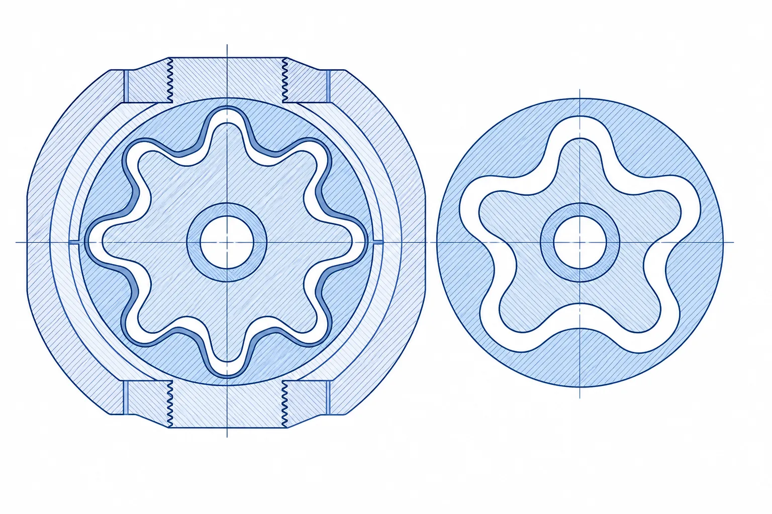
*Ilustração do conceito de engenharia: a helical power-section rotor supported for controlled correction. Não é uma fotografia do site do cliente. Force class, fixture geometry and acceptance limits must be established on representative rotors for each lobe configuration.*
What the Rotor Is — and Why Its Geometry Is Special
Inside a downhole mud motor, drilling fluid pumped through the string drives the rotor in a planetary motion inside the stator; rotation exits through a universal joint and drive shaft to turn the bit. Industry references are explicit about the geometry trade: higher lobe configurations raise output torque and lower output speed. The rotor that carries this profile is a long, sólido, heat-treated shaft — typically plated (hard chrome in classic designs, tungsten-carbide coatings in modern repair flows) to survive the abrasive, stator-interference environment. Downhole, the same rotor may run inside a deliberately bent housing for directional drilling, cycling bending stress continuously.
Two consequences follow for straightening. Primeiro, the profiled surface is a functional sealing geometry, not a shaft journal: every support and every ram foot that touches it must respect the helix. Segundo, the length-to-diameter ratio is extreme enough that the rotor’s own weight deflects it between supports — support positions during measurement are part of the measurement, and any serious process controls them explicitly.
Where the Rotor Sits in the Downhole Motor Chain
| Elemento | Função | Straightening Interest |
|---|---|---|
| Power-section rotor (helical) | Converts mud pressure into rotation inside the stator | This article — profiled long shaft, coating-sequence-critical |
| Drive shaft assembly | Transmits rotor rotation through the universal joint to the bit | Conventional precision shaft work; bending-stiff but round section — see our motor shaft straightening e pump shaft straightening pages for the method family |
| Drill string above (pipe, HWDP, collars) | Peso, rotation and mud path | Tubo de perfuração, HWDP, drill collars, kelly |
The Surface Cousin: PCP Rotors Share the Geometry, Not the Economics
Progressive cavity pumping (PCP) is the same positive-displacement principle at surface-lift scale: a helical multi-lobe rotor inside an elastomer stator, meshing along a sealing line, driven from the surface instead of by drilling mud. The rotor of a surface PCP pump is geometrically the same workpiece family as the power-section rotor this page is about — same lobe profiles, same long helix, same straightness-to-sealing dependence. Readers arriving from the PCP side should know upfront: the geometry rhymes, but the repair economics split the two worlds.
On the repair side, PCP service companies publish maintenance flows that open with visual inspection of rotor and stator and treat the rotor largely as a replaceable item (reported service documentation from PCP repair providers). The economics behind that are structural: surface PCP rotors are shorter, made in industrial volumes, and priced where a strip–straighten–recoat–revalidate loop costs more than a new rotor plus the downtime it saves. Downhole motor rotors sit at the opposite end of every one of those axes — long, coated with expensive hard chrome or tungsten carbide, and valuable enough that the remanufacturing loop (strip, inspecionar, straighten, recoat) is the industry standard. That economic asymmetry, not the geometry, is why dedicated rotor straightening machines and rotor-repair service lines exist as a market of their own.
Where straightening does enter the PCP rotor conversation is OEM manufacturing. A newly hobbed, heat-treated PCP rotor carries the same correction window described above — straighten after heat treatment, before plating — and the same profile-aware tooling rules: supports and ram feet engage the crests through form-matched soft inserts, never a point contact on a lobe flank. The force class is lower and the bed is shorter than downhole motor work, so a cell sized for PDM rotors generally covers PCP rotors — not the reverse.
For shops serving general pump repair, the round-shaft side of that world is covered separately in our industrial pump shaft straightening solution; this page remains the reference for the helical members. If your mix includes PCP rotor manufacturing, bring the lobe configurations, lengths and coating sequence to the sample-part discussion — the validation matrix is per lobe family, exactly as for downhole rotors.
Manufacturing Sequence: Straighten Before You Coat
Rotor manufacturing references describe a flow of profile machining (hobbing or milling the helix), tratamento térmico, and then surface engineering — polishing and plating, with modern shops applying carbide coatings and re-polishing. Straightening belongs between heat treatment and coating: pressing a plated or coated rotor risks cracking the coating over the correction zone, and re-grinding after correction can disturb the profile’s fit to the stator. The sequencing logic is the general rule of alisamento após tratamento térmico applied with an unforgiving surface layer at the end of the chain — once the coating is on, the correction options are essentially gone.
Remanufacturing inverts the sequence: the used rotor arrives stripped (coating removed), is inspected for profile wear, cracks and bow, then goes through correction, re-coating and final polishing. Coating contractors that advertise rotor repair with straightening in the flow are describing exactly this loop. For the straightening operation, reman rotors carry one extra caution: service exposure in bent housings means some bows are fatigue events, so correction candidacy is an engineering disposition, never a default.
Measuring Straightness on a Helical Profile
A rotating runout scan does not transfer to a multi-lobe helix the way it does to a round shaft — the profile itself dominates the signal. Practical measurement adapts along three lines: support the rotor at defined stations (controlling self-weight deflection by support placement), reference the centerline via the end journals or center holes, and read deviation from the lobe crests at intervals — clock-referencing the helix position at each station so crest readings compare like with like. Non-contact sensing helps here, for the reasons we set out in medição de retilinidade com contato versus sem contato: no probe pressure on a plated or ground crest, no fixture marks. The datum-selection logic for long stepped members follows our measuring datum selection guia, with the rotor’s end journals playing the datum role.
Helix twist is the rotor’s third geometry, alongside bow and crest runout: clock-error of the profile along the length. Like the kelly twist we describe in oilfield kelly straightening, twist is a section-form problem — pressing a bow does not remove it, and pronounced twist goes back to engineering disposition.

Process Route: Profile-Aware Pressing
Dedicated rotor straightening machines on the market are hydraulic NC presses in C-frames with reported capacities from 100 para 400 kN — that force class, for these diameters, says everything about how stiff a solid heat-treated helical shaft is. The correction route is gag-press logic as in press vs roller straightening, with the rotor-specific layer being tooling: supports and ram feet engage the profile through form-matched soft inserts that distribute load across crests, never point-contact a single lobe flank. Long members also press in shorter spans with more cycles — the bend map, not a mid-span habit, decides support spacing, and springback behavior follows the compensation discipline in compensação de retorno elástico, validated per lobe configuration because profile stiffness varies with it.
The closest methodological cousin in general manufacturing is the plasticizing screw we treat separately — another long, tratado termicamente, helically profiled shaft where straightening protects a functional flight geometry (plasticizing screw straightening). The rotor adds oilfield length, coating-sequence constraints and fatigue-history dispositions on top of that common discipline. Machine capability for any specific rotor family must come from sample-part trials; published machine envelopes elsewhere in the market (lengths into the double-digit meters) show how much this workpiece stretches a cell’s frame, handling and floor plan.

Deviation Classes and Disposition
| Desvio | Typical Origin | Posture |
|---|---|---|
| Arco global, pre-coating | Tratamento térmico, machining stress relief | Standard candidate: map, press in spans, medir novamente, settle, re-verify |
| Local bend (service) | Bent-housing operation, stuck-pipe events | Engineering review of fatigue exposure before any press |
| Bow with coating intact | Handling damage after plating | High-risk correction — coating cracking governs; usually route to strip-and-remanufacture instead |
| Helix twist | Torque/thermal events | Not press-correctable; disposition with the profile geometry owner |
| Bow plus crack indication | Fatigue | Never a straightening case; scrap-or-engineering disposition first |
Common Mistakes in Rotor Straightening Projects
- Round-shaft fixtures meeting a helix: first heavy press point-brinishes a lobe crest and the stator interface is compromised silently.
- Pressing after coating to “rescue” a bowed plated rotor — correction cracks the functional surface it was meant to save.
- Ignoring self-weight deflection in measurement by letting support positions drift between map and re-measure cycles.
- One springback factor assumed across different lobe configurations; profile stiffness changes with lobe count.
- No fatigue disposition step for service-bent rotors from directional programs.
One operational note from long-shaft cells generally: at rotor lengths, the bottleneck is rarely press force — it is handling and datum discipline. Every extra lift between map, press and re-measure is an opportunity for a new ding on a finished crest, and every support reposition without a recorded station corrupts the trend data that sizes the next press increment. Cells that treat support positions, lift points and sensor stations as numbered, recorded setup items (rather than operator habits) hold their acceptance bands across shifts; cells that improvise chase the same rotor twice.
RFQ Data for a Rotor-Grade Cell
A realistic equipment conversation starts from: lobe configurations in your mix; across-crest diameters and total lengths (with weights); steel family and hardness; whether parts arrive bare, machined or coated; inbound bow statistics; the acceptance straightness band and its measurement method; annual volume split between OEM and remanufacturing; and the hall’s handling envelope — at rotor lengths, crane and support logistics are half the engineering. From that base, a sample test on representative rotors per lobe family fixes force class, fixture inserts and cycle time. Machine sizing honesty matters here: this is a workpiece family where published competitor envelopes run to fourteen-meter beds, so scope your own lengths precisely and verify against demonstrated sample results rather than nameplate optimism.
Perguntas frequentes
Can a mud motor rotor be straightened?
Yes — before coating. The remanufacturing industry straightens stripped rotors as a standard step before re-plating or carbide coating, and machine builders sell dedicated NC rotor presses for exactly this workpiece. Plated or coated rotors are a different, high-risk case where correction usually loses to strip-and-redo.
What about the drive shaft below the power section?
Downhole motor drive shafts and universal-joint members are round precision shafts — demanding, but conventional straightening work in the same method family as our automatic motor shaft straightening soluções, sized to the oilfield lengths involved.
How is straightness measured on a helical profile?
By referencing the centerline from end journals or centers, supporting at controlled stations to manage self-weight deflection, and reading deviation at clock-referenced lobe crest positions along the length — usually with non-contact sensing to protect finished surfaces.
Does the lobe configuration change the machine requirement?
It changes stiffness and tooling. More lobes change section mechanics and the insert geometry that safely engages the profile, which is why process validation is done per lobe family on sample parts rather than transferred between configurations.
Summary and Next Step
Mud motor rotor straightening is precision long-shaft work with an unforgiving twist: the surface is a functional helix, the coating sequence locks the correction window, and fatigue history gates candidacy. Classifique o desvio, respect the profile in every tooling contact, measure with controlled supports, and validate the process per lobe family on real rotors. If you are building or rebuilding a rotor line, send the configuration mix, lengths and acceptance bands — and pair this with our pages on plasticizing screw straightening e broca de canhão e endireitamento de broca de furo profundo for the adjacent long-shaft disciplines.