
Stopniowy element wiertła medycznego nie jest jednolitym wałem. Jego duże i małe sekcje cylindryczne, plecy, promienie przejścia, Koniec tnący i koniec napędowy mogą pełnić inną rolę funkcjonalną, sztywność i dopuszczalny stan styku. Dlatego system prostowania musi mierzyć i korygować obrabiany przedmiot po przekroju, zamiast traktować całą długość jako jeden zwykły okrągły pręt.
Celem nie jest po prostu zmniejszenie wartości wskaźnika. Proces musi zachować cechy funkcjonalne, unikaj ładowania wrażliwych przejść i uzyskaj wynik zgodny z rysunkiem klienta i metodą kontroli.
Dlaczego stopniowe ćwiczenia medyczne wymagają dedykowanego procesu
Rodziny ćwiczeń medycznych są bardzo zróżnicowane. Oficjalne informacje o produkcie firmy DePuy Synthes odnoszą się do wierteł stopniowanych stosowanych z ogranicznikami wiercenia, podczas gdy Stryker oferuje wiertła o różnych średnicach i długościach. Referencje te potwierdzają różnorodność obrabianych przedmiotów; nie oznacza to, że do każdego ćwiczenia medycznego stosuje się ten sam materiał, wymagania dotyczące geometrii lub akceptacji.
Do projektu prostowania, poniższe funkcje zmieniają projekt procesu:
| Funkcja przedmiotu obrabianego | Konsekwencja prostowania |
|---|---|
| Wiele średnic cylindrycznych | Każda sekcja może wymagać innej pozycji pomiarowej, rozpiętość wsparcia i granica korekcji |
| Ramiona i promienie przejściowe | Lokalna koncentracja naprężeń powoduje, że są to słabe domyślne strefy nacisku lub wsparcia |
| Długa część o zmniejszonej średnicy | Niższa sztywność zginania zwiększa ugięcie grawitacyjne i wrażliwość na siłę pomiarową |
| Końcówka tnąca lub ząbkowana | Geometria cięcia musi być chroniona przed szczękami, sondy i narzędzia korekcyjne |
| Prowadzić, złącze lub element płaski | Może to być funkcjonalna podstawa odniesienia, ale nie jest to automatycznie okrągła powierzchnia bicia |
| Korpus poddany obróbce cieplnej lub wykończony powierzchniowo | Wiosna, ryzyko oznakowania i pęknięcia należy sprawdzić na reprezentatywnych próbkach |

Ta prawdziwa rama projektu przedstawia długi schodkowy element utrzymywany na stanowisku pomiarowym i korekcyjnym. Potwierdza rozmieszczenie przedmiotu obrabianego i wyposażenia, ale nie ustanawia materiału, wymiary, dokładność lub czas cyklu.
Zdefiniuj wymagania dotyczące rysunku przed wyborem maszyny
Słowo „prostość” jest często używane w odniesieniu do kilku różnych cech. ISO 1101 zapewnia język tolerancji geometrycznej, ale rysunek nadal musi identyfikować rzeczywistą charakterystykę i układ odniesienia.
Przed wyceną lub próbą próbną, potwierdzić, czy klient potrzebuje:
- prostoliniowość osi jednego przekroju cylindrycznego;
- bicie promieniowe lub całkowite bicie wskazane w odniesieniu do wybranych czopów;
- współosiowość lub położenie pomiędzy dwiema schodkowymi sekcjami;
- wymóg koperty pełnej długości;
- lokalna prostoliniowość na określoną długość pomiarową;
- lub połączone wymaganie obejmujące geometrię i stan powierzchni.
Wymagania te nie są zamienne. Przedmiot obrabiany może wykazywać akceptowalne bicie w jednej sekcji, podczas gdy inna sekcja o zmniejszonej średnicy pozostaje poza tolerancją ciągnienia. Możliwe jest również ulepszenie jednego śladu wskaźnika przy jednoczesnym pogorszeniu współosiowości między sekcjami, jeśli strategia odniesienia jest błędna.
Zgłoszone dane wejściowe projektu nie stanowią specyfikacji końcowych
Aplikacja źródłowa opisała obrabiany przedmiot w przybliżeniu 230 mm długości i podawane średnice w pobliżu 7.9, 6.9 I 5.9 mm. Wspomniano także o 0.05 cel mm. Wartości te są przydatne przy planowaniu przykładowej dyskusji, nie są one jednak tutaj traktowane jako zweryfikowane wyniki produkcyjne.
Przed zatwierdzeniem technicznym, klient musi wyjaśnić:
| Wymagane dane wejściowe | Dlaczego to ma znaczenie |
|---|---|
| Kontrolowane rysowanie i rewizja | Zapobiega budowaniu narzędzi i inspekcji w oparciu o przestarzałą geometrię |
| Stan materiału i obróbki cieplnej | Określa sztywność, sprężynowanie, ryzyko pęknięcia i dopuszczalny nacisk kontaktowy |
| Etap produkcji | Określa, czy elementy tnące, powłoka, pasywacja lub ostateczne wykończenie już istnieją |
| Punkt odniesienia i charakterystyka | Określa wsparcie, obrót i położenie sondy |
| Początkowy rozkład zgięcia | Określa wymagany skok korekcyjny i możliwość odzyskania części |
| Zabronione strefy kontaktu | Chroni ramiona, cechy cięcia, wykończenia i funkcjonalne powierzchnie łączące |
| Próbki pomiarowe lub korelacyjne klienta | Sprawia, że wyniki pracy maszyny są porównywalne z końcową kontrolą odbiorczą |
Strategia pomiaru specyficzna dla sekcji
System pomiarowy nie powinien zakładać, że jedna para środków lub jedna powierzchnia cylindryczna reprezentuje cały przedmiot obrabiany.
1. Ustal podstawę funkcjonalną
Wybierz powierzchnie odniesienia z rysunku i logiki montażu końcowego. Odpowiednimi kandydatami mogą być gotowe czasopisma, zdefiniowaną średnicę trzpienia lub kontrolowaną cechę środkową. Ramię, flet, reliefowa lub nieobrobiona, pusta powierzchnia nie powinna stać się punktem odniesienia tylko dlatego, że jest łatwa w kontakcie.
2. Sterowanie wsparciem i efektami grawitacyjnymi
Długie, zredukowane sekcje uginają się pod własnym ciężarem. Podparcie poziome nie eliminuje błędu grawitacji. Metoda przykładowa musi definiować lokalizacje podpór, wolna rozpiętość, orientacja przedmiotu obrabianego, prędkość obrotowa i siła sondy. Urządzenie i miernik klienta powinny sprawdzać tę samą charakterystykę w skorelowanych warunkach.
3. Zmierz więcej niż jedną sekcję
Użyj zdefiniowanych na rysunku stanowisk osiowych dla odpowiednich średnic. Sonda musi pozostać na zatwierdzonym cylindrycznym podłożu i nie może podczas pomiaru przechodzić przez pobocze lub relief. Jeśli część zawiera element inny niż okrągły, system może wymagać indeksowania kątowego lub innego czujnika zamiast konwencjonalnego wskaźnika stykowego.

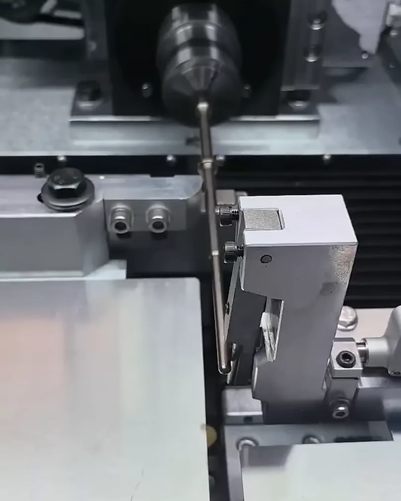
Klatka wideo przedstawia obrabiany przedmiot w pobliżu kompaktowego zespołu czujnikowo-korekcyjnego. Dokładny typ czujnika i siła zależą od projektu i muszą zostać potwierdzone podczas projektowania maszyny.
Projekt chronionej strefy korekcyjnej
Korekcja punktowa powinna działać wyłącznie na zatwierdzone strefy stalowe. Nie należy go umieszczać automatycznie w miejscu największego zmierzonego odchylenia, jeśli tym miejscem jest pobocze, promień przejścia, element cięcia lub inny ograniczony obszar.
Przed programowaniem utwórz mapę korekcyjną:
| Typ strefy | Domyślna reguła |
|---|---|
| Stabilna cylindryczna część korpusu | Strefa wsparcia kandydata lub korekta po przeglądzie ciśnienia powierzchniowego |
| Długi odcinek o zmniejszonej średnicy | Stosuj mniejsze przyrosty siły i węższe limity ruchu |
| Promień barku i przejścia | Zabroniona lub specjalnie zaprojektowana strefa kontaktu |
| Cięcie, koniec ząbkowany lub karbowany | Chronić przed bezpośrednim dociśnięciem i mocnym zaciśnięciem |
| Funkcja napędu/sprzęgu | Lokalizuj tylko za pomocą narzędzi specyficznych dla danego wariantu |
| Powierzchnia wykończona lub powlekana | Użyj zatwierdzonych materiałów stykowych i kryteriów znakowania |
Sekwencja kontrolna powinna stosować ograniczoną korekcję, zwolnij ładunek, ponownie zmierz i zaktualizuj następną akcję. Ta pętla „zmierz – popraw – zmierz ponownie” jest niezbędna, ponieważ sprężynowanie może różnić się w zależności od przekroju średnicy i partii poddanej obróbce cieplnej.
Przykładowy proces automatyczny
Automatyczną stopniowaną komorę prostowania wierteł medycznych można skonfigurować w następującej kolejności:
- Załaduj lub przyjmij obrabiany przedmiot bez uderzania w elementy tnące i występy.
- Potwierdź obecność części i, gdzie jest to wymagane, tożsamość wariantowa.
- Zlokalizuj zatwierdzone powierzchnie odniesienia i skontroluj położenie osiowe.
- Obróć obrabiany przedmiot i zmierz określone sekcje przy kontrolowanym podparciu i sile pomiarowej.
- Oblicz kierunek zagięcia i określ zatwierdzoną lokalizację korekty.
- Zastosuj ograniczoną korekcję punktu z monitorowaniem siły lub przemieszczenia.
- Uwolnienie, obróć i ponownie zmierz odpowiednie sekcje.
- Powtarzaj tylko w ramach zweryfikowanej iteracji, ograniczenia siły i ruchu.
- Sklasyfikuj część jako zaakceptowaną, odrzucone lub wymagające przeglądu technicznego.
- Jeśli wymagana jest identyfikowalność, zapisz wynik końcowy i odpowiednie dane procesu.
Rzeczywista komórka może wymagać ręcznego ładowania, magazyn, robotem lub inną metodą przenoszenia. Poziom automatyzacji powinien być zgodny z rodziną części, wielkość partii, wymagania dotyczące stabilności orientacji i czystości, a nie zakładane na podstawie jednego filmu demonstracyjnego.
Prawdziwy krokowy film dotyczący prostowania wierteł medycznych
Poniższy film z kanału Prostownica przedstawia długi element wiertła medycznego na automatycznym stanowisku pomiarowo-korekcyjnym.
Film przedstawia ruch sprzętu i fizyczny przedmiot obrabiany. Nie jest to protokół kontroli i nie stanowi dowodu na powszechną tolerancję, tempo produkcji, wydajność lub akceptacja klienta.
Walidacja i akceptacja próbki
Reprezentatywna próba próbna jest właściwą podstawą potwierdzenia wykonalności. Powinien zawierać najgorsze wiarygodne kombinacje średnic, długość, stan materialny, początkowe zagięcie i stan powierzchni.
Zalecany przykładowy zapis
| Nagrywać | Minimalna zawartość |
|---|---|
| Tożsamość części | Numer rysunku, rewizja, etap partii i produkcji |
| Nadchodząca geometria | Charakterystyczny, fakt, stacje osiowe i zmierzone wartości |
| Ustawienia procesu | Stanowiska wsparcia, strefy korekcyjne, limity siły/przesunięcia i liczba iteracji |
| Ostateczna geometria | Wyniki z maszyny i skorelowanego miernika klienta |
| Stan powierzchni | Znaki, wgniecenia, kontrola uszkodzeń powłoki i cech skrawania |
| Stan materialny | W stosownych przypadkach dowody dotyczące twardości lub obróbki cieplnej |
| Wyjątki | Odrzucone części, naruszeń limitów i dyspozycji inżynieryjnych |
Zgłoszony cel, taki jak 0.05 mm nie może stać się gwarancją na maszynę do czasu uzyskania charakterystyki, fakt, metoda pomiaru, uzgodniono stan początkowy i reprezentatywne wyniki próbek.
Granica jakości wyrobów medycznych
ISO 13485 określa wymagania dotyczące zarządzania jakością dla wyrobów medycznych. W Stanach Zjednoczonych, rozporządzenie FDA w sprawie systemu zarządzania jakością weszło w życie w lutym 2, 2026 i zawiera ISO 13485:2016 przez odniesienie.
Prostownica może wspierać kontrolowany proces klienta poprzez przepisy, poziomy dostępu, planowanie kalibracji, rejestrowanie wyników i kontrola zmian. Sama maszyna nie certyfikuje produktu klienta, zatwierdzić cały proces produkcyjny lub ustalić zgodność z przepisami. Obowiązki te pozostają w gestii legalnego producenta i jego systemu jakości.
Rozwiązanie to dotyczy komponentów na etapie produkcji. Nie jest to propozycja naprawy lub ponownego użycia zużytych wierteł chirurgicznych.
Czego potrzebujemy do propozycji stopniowej wiertarki medycznej
Niezależnie od tego, czy modernizujesz istniejącą stopniowaną linię wierteł medycznych, czy kupujesz nową, the przewodnik po wyborze prostownicy i obraz budżetu na maszynę do prostowania ustal kompromisy przed rozmową z dostawcami.
Wyślij poniższe informacje do przeglądu technicznego:
- rysunek i rewizja;
- tworzywo, obróbka cieplna i stan powierzchni;
- etap produkcji, na którym wymagane jest prostowanie;
- sekcje średnicy, długość całkowita i geometria ramion;
- charakterystyka zdefiniowana na rysunku, punkt odniesienia i granica akceptacji;
- początkowy rozkład zgięcia i próg odrzutu;
- zabronione strefy kontaktu;
- metoda kontroli klienta i dostępne próbki korelacyjne;
- wymagana wielkość produkcji i preferencje dotyczące załadunku;
- identyfikowalność, wymagania dotyczące receptur i eksportu danych.
Nasz zespół wykorzysta te dane wejściowe do zdefiniowania przykładowego testu, koncepcja pomiaru, mapa korekcyjna i konfiguracja maszyny.
Często zadawane pytania
Czy jeden program może obejmować kilka stopniowanych rozmiarów wierteł medycznych??
Prawdopodobnie, ale każdy wariant wymaga kontrolowanej receptury i kompatybilnego lokalizatora, wsparcie, mapa stacji pomiarowej i strefy korekcyjnej. Podobna długość całkowita nie świadczy o tym, że można dzielić oprzyrządowanie.
Czy maszyna może zagwarantować 0.05 mm?
Nie na podstawie samej wartości docelowej. Charakterystyka, fakt, miernik, początkowy zakręt, stan materiału i wyniki próbek muszą zostać określone przed podjęciem zobowiązania w zakresie tolerancji.
Czy prostowanie uszkodzi ramiona lub wykończoną powierzchnię??
Rozwiązanie zaprojektowano tak, aby uniknąć bezpośredniego obciążenia ograniczonych elementów i kontrolować nacisk kontaktowy. Ostateczna akceptacja powierzchni nadal wymaga reprezentatywnej kontroli próbki.
Czy to ten sam proces, co prostowanie jednolitego pręta medycznego?
NIE. Wiele średnic zmienia sztywność, transfer danych, lokalizacje sond i dopuszczalne strefy korekcji. Proces musi być specyficzny dla sekcji.
Omów swój przedmiot
Przejrzyj nasze Strona aplikacji wiertarki medycznej I Rozwiązania w zakresie urządzeń medycznych, Lub skontaktuj się z naszym zespołem zajmującym się prostowaniem z rysunkiem i przykładowymi informacjami.