
Most automation content about machine tending is written for CNC machines: the robot opens the door, swaps a finished part for a blank, closes the door, and repeats to a steady beat. Tending a straightening machine looks similar from the outside, but the process inside the machine behaves differently – the cycle time varies part to part, a measurable fraction of parts leave as rejects that need their own handling path, and the workpieces are frequently finished or near-finished surfaces that must not be marked. A cell designed on CNC assumptions will disappoint; a cell designed around how a straightener actually runs will run for years.
This article explains what changes when the tended machine is an automatic straightening press, what tending architecture options exist, and how to specify and accept a robot cell around a straightening process. For the process inside the machine itself, beginnen met hoe het automatisch richten van de as werkt.
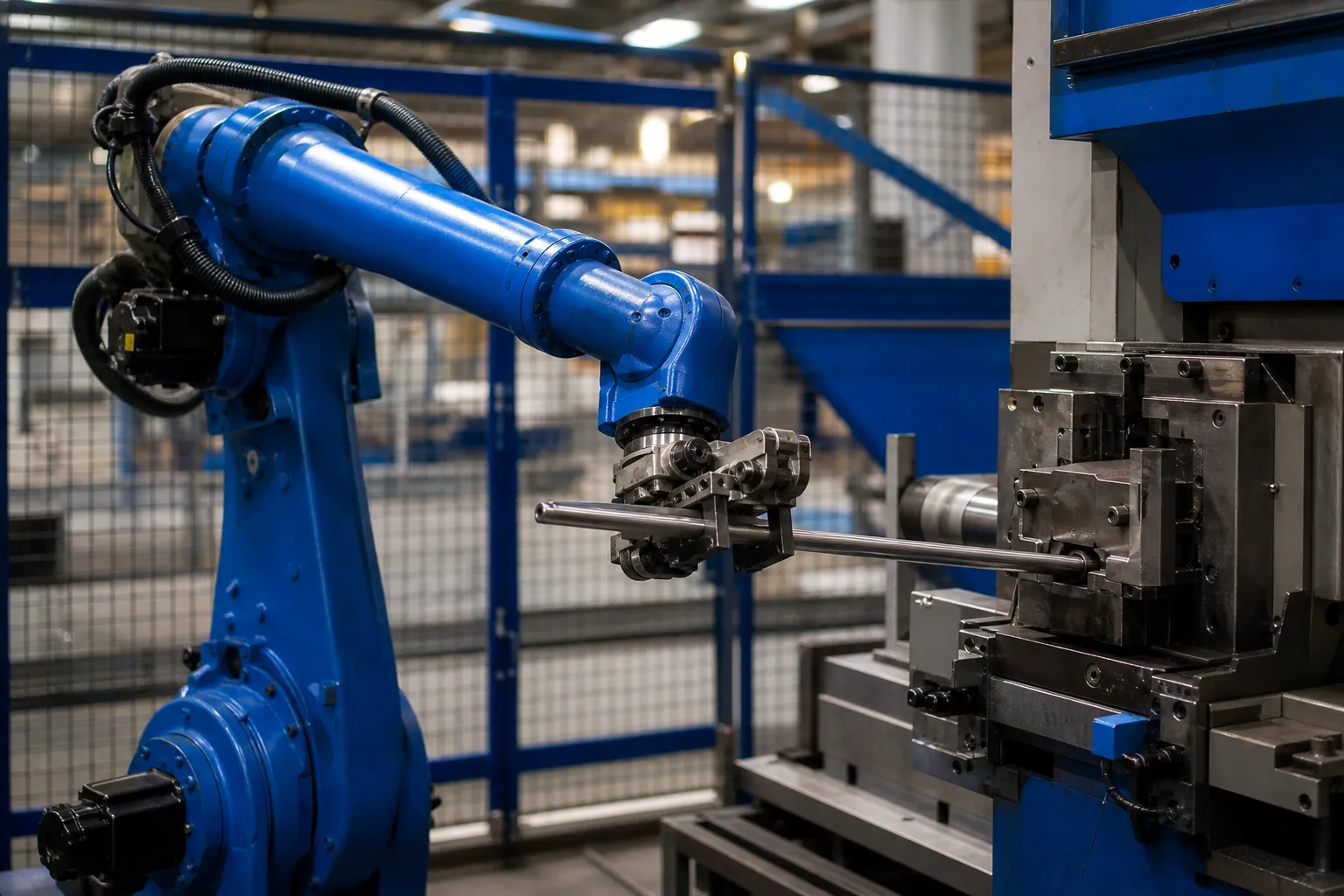
Why a Straightener Is Not a CNC from the Robot’s Point of View
Three process characteristics drive every tending decision for a straightening machine:
- The cycle is variable. A straightening cycle is a loop: meeteenheid, druk, opnieuw meten, and repeat until the part is inside tolerance. A part with a small, simple bend may pass after one press; a part with a multi-plane bend may need several correction iterations. The machine’s cycle time is therefore a distribution, geen constante – and the tending system has to cope with the tail of that distribution without starving or blocking the machine.
- Some parts fail. A certain share of parts will not reach tolerance within the allowed press count and leave the machine as NOK. In a manual operation the operator drops them in the red bin; in an automated cell the tending system is the NOK sorting mechanism, and it needs a physical lane and a data trail to go with it. The definitions behind good-part, rework and reject dispositions are covered in NOK sorteer- en herbewerkingslimieten in een richtlijn.
- Surfaces are fragile. Straightening often happens late in the process chain – na warmtebehandeling, sometimes after grinding. Tijdschriften, splines and seal diameters can be finished surfaces, and a gripper that grabs the wrong zone transfers force onto geometry the customer will measure. Contact-zone discipline is the same problem discussed in oppervlaktebeschermingsgereedschap bij het rechttrekken, applied to the robot instead of the press.
None of these characteristics is exotic. They simply mean the tending concept has to be engineered against the straightener’s real behavior, not against a generic machine-tending template.
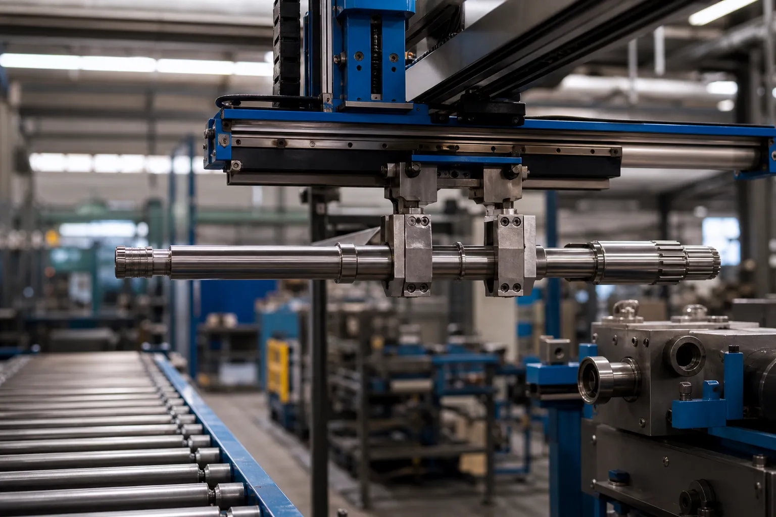
Anatomy of an Automated Straightening Cycle
Breaking the cycle into its timed elements shows where the robot gains or loses the day:
- Deel presentatie. The part arrives at a defined position and orientation – from an infeed conveyor with orientation fixtures, a drawer system, a tray, or a vibration-free staging table for long slender shafts.
- Laden. The robot places the part onto the machine’s supports. Placement repeatability matters because the machine’s measurement rotates the part between centers or rollers; a part seated wrong measures wrong.
- Meeteenheid – druk – opnieuw meten. The machine runs its correction loop autonomously. This is the variable-length portion of the cycle.
- Unload with disposition. The robot receives a pass/fail signal per part and deposits it in the matching lane: good parts to the outfeed, rework candidates to their lane, rejects to the NOK lane, each with the measurement record attached.
In a well-balanced cell, the machine’s correction loop is the pacemaker, and the robot’s job is to be ready the moment the door signal comes – never making the machine wait for a part, never making parts wait in unprotected staging.
Doing the arithmetic honestly matters more here than in CNC tending. With a constant cycle you compare one number against takt; with a distribution you size the cell against its tail. Take the machine’s measured cycle spread from the process data – typical parts versus the slowest decile that need several press iterations – and check the takt against the slow case, not the average. If the slow case breaks takt, the remedies are structural: a small input buffer so the robot decouples from the conveyor, a second machine sharing one robot, or agreed criteria that route multi-iteration parts to a different operation. Sizing the cell on the average cycle is the single most common way automated straightening lines end up missing rate in production.
Tending Architecture Options
Four architectures cover most straightening installations:
- Six-axis robot cell. An articulated robot in a fenced or light-guarded cell, feeding the machine from conveyor or drawer. The most flexible option: one robot can serve one machine, two machines, or a machine plus marking and measurement stations.
- Gantry loader. An overhead gantry serving an inline machine. Faster on short, heavy parts and very space-efficient, at the cost of flexibility for future part changes.
- Step-through conveyor with machine-integrated handling. On many automatic straighteners, an inline roller conveyor passes parts straight through the machine, which loads itself. Where this exists, the automation project shifts upstream and downstream – feeding the conveyor and handling the output – rather than interfacing with the press directly.
- Manual tending on a semiautomatic machine. For low volumes or wide part variety, manual load and unload on a machine that still runs its measure-press-remeasure loop automatically remains a legitimate answer; the trade-offs are laid out in manual vs automatic straightening.
The right choice falls out of three numbers: takt requirement, part variety, and the spread of the machine’s cycle-time distribution. Where the distribution has a long tail, dual-position fixtures or a small buffer let the robot decouple from the slowest parts instead of idling.

Grippers and Part Handling
The gripper is where the straightening-specific risk concentrates. Practical design rules:
- Grip on safe zones only. Define the permitted contact zones from the drawing – typically shaft bodies between features – and design the gripper to those zones, with contact materials that cannot mark hardened surfaces.
- Respect slenderness. Lang, thin shafts need support, not just grip. Two-point or cradle-style handling keeps bending stress from the part’s own weight out of the equation; a single-point grip on a long heavy shaft can bow it enough to matter at tight tolerances.
- Orientation discipline. If the machine references a feature – a flange, a hole, a flat – the presentation system must deliver the part in a known orientation, or the cell needs a vision or sensor-based correction step before load.
- Omschakeling. Part families change gripper fingers, support contours, and lane positions. Quick-change hardware and stored recipes keep a mixed-part cell productive.
- Cope with the environment. Straightening presses work with oil and on parts straight out of heat treatment. Gripper surfaces, sensors and drop-protection design have to function with contaminated surfaces, and any part-retention check should be validated on a realistically oily part, not a clean demonstration piece.
Common Failure Modes in Straightening Cells
Projects that struggle tend to struggle in the same places. The machine starves because the cell was sized on average cycle time instead of the tail. NOK parts back up because the reject lane was added as an afterthought and fills during a bad batch. Parts come back marked because the gripper was proven on blanks and the first ground journal arrived months later. The cell becomes unmaintainable because the machine interface was reverse-engineered after commissioning instead of specified with the machine. And measurement results stop matching production counts because the robot’s placement and the machine’s records were never tied together into one per-part data stream. Every one of these is preventable at the specification stage – which is why interface definitions, disposition lanes, contact zones and data flow belong in the same planning document as the robot reach study.
The Machine Interface: Signals That Matter
A tending cell lives or dies on its interface with the straightener’s control. The signal set worth specifying explicitly includes: part-present and door/safety states, cycle start handshake, cycle complete with per-part disposition (doorgang / herwerken / GENOEG), fault and e-stop categories, and the data channel that carries per-part measurement results to the plant system. Deciding this interface early – ideally at the machine quotation stage, using a checklist of the kind in the straightening machine FAT checklist – prevents the classic integration failure where machine and cell technically run but share no usable information.
One subtle point deserves emphasis: adding a robot changes the measurement system boundary. If operators previously placed parts by hand with skill and consistency, the robot’s placement repeatability becomes part of the measurement chain. A gage study performed with manual loading does not automatically transfer to robotic loading; re-running the measurement-system analysis of the kind described in Gage R&R voor het rechttrekken van lijnen with the cell loading the machine is the honest way to validate the automated configuration.

A note on the images in this article: they are engineering concept illustrations created for this article, not photographs of a specific customer line, machine model, or installation, and they are intended to support the process discussion only.
Veelgestelde vragen
Can one robot serve two straightening machines?
Ja, when the combined cycle allows it. The arithmetic is driven by the machines’ cycle-time distributions and the robot’s load/unload and transit times, plus a margin for the tail – the parts that need extra press iterations. Cell controllers queue requests from both machines and the robot serves them in order; the risk to design out is one machine waiting while the other’s part is in the gripper.
How do robots handle parts that fail straightening?
As a first-class output lane, geen bijzaak. The machine signals the disposition per part; the robot routes NOK parts to a dedicated lane or bin, and the disposition travels with the part’s measurement record so downstream rework or scrap decisions are documented. The lanes and their rules are worth designing before the cell is built, using the rework-limit thinking in the NOK sorting article.
Does robotic tending improve measurement quality?
It changes it – in either direction. Consistent robotic placement removes operator-to-operator variation in how parts are seated, which usually helps repeatability. But any placement inaccuracy becomes systematic, which is why the measurement-system validation should be repeated with the robot in the loop before the cell is signed off.
What safety standards apply to a straightening cell?
The same machinery-safety framework as any press-adjacent automated cell: safeguarded envelope with interlocked access, light curtains or scanners at the hand-off points where operators interact, and safe stop behavior coordinated between robot and press controllers. The specifics belong to the risk assessment for the individual installation.
Conclusie
Robot tending turns an automatic straightening machine into a true production cell – but only when the cell is engineered around the straightener’s actual behavior: variable correction cycles, NOK dispositions that need lanes and data, and workpieces whose surfaces must survive every transfer. Specify the machine interface early, keep gripper contact inside drawing-approved zones, validate the measurement system with the robot in the loop, and accept the whole cell against a checklist rather than a demonstration. If you are planning automation around straightening machines and want to talk through layouts, rates, and interface definitions for your part spectrum, that is exactly the conversation we work through with production teams.