
Garā lodveida tapa nav vienkāršs apaļš stienis, un tas nav pilnīgs stieņa komplekts. Tas apvieno slaidu kātu ar ļoti noslogotu lodveida galvu, pārejas rādiuss un, atkarībā no ražošanas stadijas, dzīvokļi, konusveida, vītnes vai gatavās gultņu virsmas. Iztaisnošanas metodei ir jākoriģē izmantojamais kāts, neripojot vai nespiežot funkcionālās zonas, kas nav paredzētas saskarei.
Šī iemesla dēļ, garu lodveida tapu iztaisnošanas risinājums sākas ar zīmēšanu un izgatavošanas ceļu. Veltņu process var būt efektīvs pietiekami vienmērīgam kātam un sadalītam izliekumam; izmērītā punkta korekcija var būt drošāka, ja izmantojamais veltņa kontakta garums ir īss vai ja daļai ir pabeigtas īpašības, kurām nepieciešams selektīvs kontakts.
Ball Stud, Lodveida šarnīrs un stienis ir dažādi produkti
ZF šasijas lodveida šarnīrsavienojumu apraksta kā tērauda lodveida tapu, kas darbojas ieeļļotā gultņa kausā korpusa iekšpusē. ZF arī apraksta savienojuma stieni kā savienojumu, kurā ir iekšējie un ārējie lodveida savienojumi, kas savienoti ar regulēšanas vītni. Projekta fotoattēlā redzamās sagataves ir atsevišķas garās lodveida tapu sagataves, nesamontēti lodveida savienojumi vai stieņi.

Attēlā redzamas īstas melnas virsmas garas lodveida tapas sagataves ar lodīšu galviņām un slaidiem korpusiem. Tas nenosaka tērauda klasi, cietība, izmēriem, galīgā ģeometrija vai klienta pieņemšana.
| Produkts/funkcija | Iztaisnošanas nozīme |
|---|---|
| Auksti kalta lodveida kniedes sagatave | Mēroga un izmēru izmaiņas ietekmē barošanu, kontakts un mērīšana |
| Bumbas galva | Jāvada vai jānotīra, nesabojājot turpmāko gultņa virsmu |
| Pāreja no galvas līdz kātam | Augsta ģeometriskā un noguruma nozīme; parasti tiek izslēgti no koncentrētas korekcijas |
| Vienveidīgs cilindrisks kāts | Kandidātzona apstiprinātam nepārtrauktam veltņa kontaktam |
| Dzīvoklis, spline vai uzgriežņu atslēgas funkcija | Maina rotāciju un var pārtraukt veltņa atbalstu |
| Konusveida vai vītne | Funkcionāla montāžas zona, kurai nepieciešama aizsargāta apstrāde un mērījumu definīcija |
| Gatavā/rūdīta virsma | Nepieciešama virsmas zīme, atlikušā sprieguma un plaisu kontrole |
Izvēlieties ražošanas posmu pirms iekārtas
Viena un tā pati sastāvdaļa katrā ražošanas posmā var darboties ļoti atšķirīgi.
| Skatuves | Tipisks iztaisnošanas iemesls | Galvenā vadība |
|---|---|---|
| Pēc aukstās kalšanas | Noņemiet formēšanas/izgrūšanas radīto līkumu un sagatavojiet apstrādei | Mērogs, izmēru izplatība un dāsnas, bet noteiktas kontaktu zonas |
| Pēc rupjas apstrādes | Pirms pabeigšanas atjaunojiet ģeometriju | Aizsargājiet atsauces diametrus un saglabājiet apstrādes pielaidi |
| Pēc termiskās apstrādes | Pareiza termiskās apstrādes deformācija | Cietības profils, atspere, plaisu risks un ierobežots korekcijas logs |
| Pēc slīpēšanas/pulēšanas | Iepazīstieties ar galīgo ģeometriju | Ļoti stingras virsmas saskares un mērījumu korelācijas prasības |
| Pēc pārklāšanas/pārklāšanas | Parasti izņēmuma gadījums | Pārklājuma bojājumi, ar ūdeņradi saistīts risks un klientu apstiprinājums |
Projekta fotoattēli izskatās saskaņoti ar tumšo, nepabeigtas sagataves un rullīšu iztaisnošanas stacija. Tie nepierāda precīzu ražošanas posmu. Priekšlikumā ir jānorāda šis posms pirms instrumentu vai garantēto rezultātu noteikšanas.
Nepieciešamās projekta ievades
| Ievade | Nepieciešamā detaļa |
|---|---|
| Zīmējums | Pārskatīšana, kontrolētās zonas, datums, pielaides un aizliegtās saskares zonas |
| Ģeometrija | Bumbiņas diametrs, kāta diametri, garums, pāreja, dzīvokļi, konusveida un vītnes |
| Materiāls | Tērauda marka, kalšanas stāvoklis un attiecīgās mehāniskās īpašības |
| Termiskā apstrāde | Caur/indukcijas/korpusa sacietēšana, cietības profils un apstrādes secība |
| Virsma | Mērogs, mehāniskā apstrāde, slīpēšana, shot peening, pārklājums un pieļaujamās zīmes |
| Ienākošais līkums | Lielums, virziens un aksiālais sadalījums reprezentatīvajās partijās |
| Galīgais raksturlielums | Kāta taisnums, atvasinātās ass taisnums, noplūdes vai funkcionālas montāžas rezultāts |
| Ražošanas mērķis | Daļu maisījums, izvade, iekraušana, pārbaudes paraugu ņemšana un maiņa |
Iepriekšējā lapā bija minēts 20–45 HRC diapazons un a 0.2 mm mērķis. Tie paliek ziņojumā ievadītie dati līdz faktiskajam daļas stāvoklim, raksturīgs, kontrolētais garums un gabarīts ir dokumentēti.
Definējiet, ko nozīmē “0,2 mm taisnums”.
| Iespējamā prasība | Nepieciešamā definīcija |
|---|---|
| Kāta virsmas-elementa taisnums | Kurš virsmas elements un kontrolētais aksiālais garums |
| Atvasināts kāta ass taisnums | Kā ass tiek konstruēta no izmērītām sekcijām |
| Radiālais izskrējiens | Rotācijas datums, zondes atrašanās vieta un leņķiskā paraugu ņemšana |
| Izlīdzināšana no lodes līdz kātam | Bumbu centra konstrukcija un kāta atsauce |
| Konusveida/vītnes attiecības | Datuma ass, funkcionālais gabarīts un pieņemama variācija |
| Maksimālā sprauga armatūrai | Atbalsta atstarpes, orientācijas un mērinstrumentu metode |
Ciparnīcas indikators uz atbalsta stiprinājuma, centra izskrējiena tests un pilna profila taisnuma novērtējums nesniedz savstarpēji aizstājamus rezultātus. Mašīnas pieņemšanai ir jāizmanto zīmējumam raksturīgais raksturlielums un jāatbilst klienta galīgajam gabarītam.
Kad rullīšu iztaisnošana ir kandidāts
Divu ruļļu taisnotājus plaši izmanto apaļajiem stieņiem, un ražotāji tos raksturo kā tādus, kas izmanto pretējas formas ruļļus, lai nepārtrauktā procesā saliektu un pagrieztu stieni. Danieli atšķir arī divripu, vairāku ruļļu un citi stieņu iztaisnošanas līdzekļi dažādiem pielietojumiem. Šie principi atbalsta procesu ģimeni; tie nepierāda, ka katra lodīšu tapa var iziet cauri vienam un tam pašam ruļļu komplektam.
Rullīšu process tiek novērtēts, kad:
- kātam ir pietiekami vienmērīgs kontakta garums;
- lodītes galva, pāreja, dzīvokļus un gala elementus var notīrīt vai droši vadīt;
- izliekums ir sadalīts, un to var koriģēt, izmantojot apstiprināto ripojuma līkni un spiedienu;
- virsmas specifikācija pieļauj nepārtrauktu rotāciju/kontaktu;
- daļa nevar aizbēgt, gailis vai ievārījums, kad galva tuvojas vadotnei;
- paraugiem ir pieņemama ģeometrija, virsmas un metalurģiskais stāvoklis.
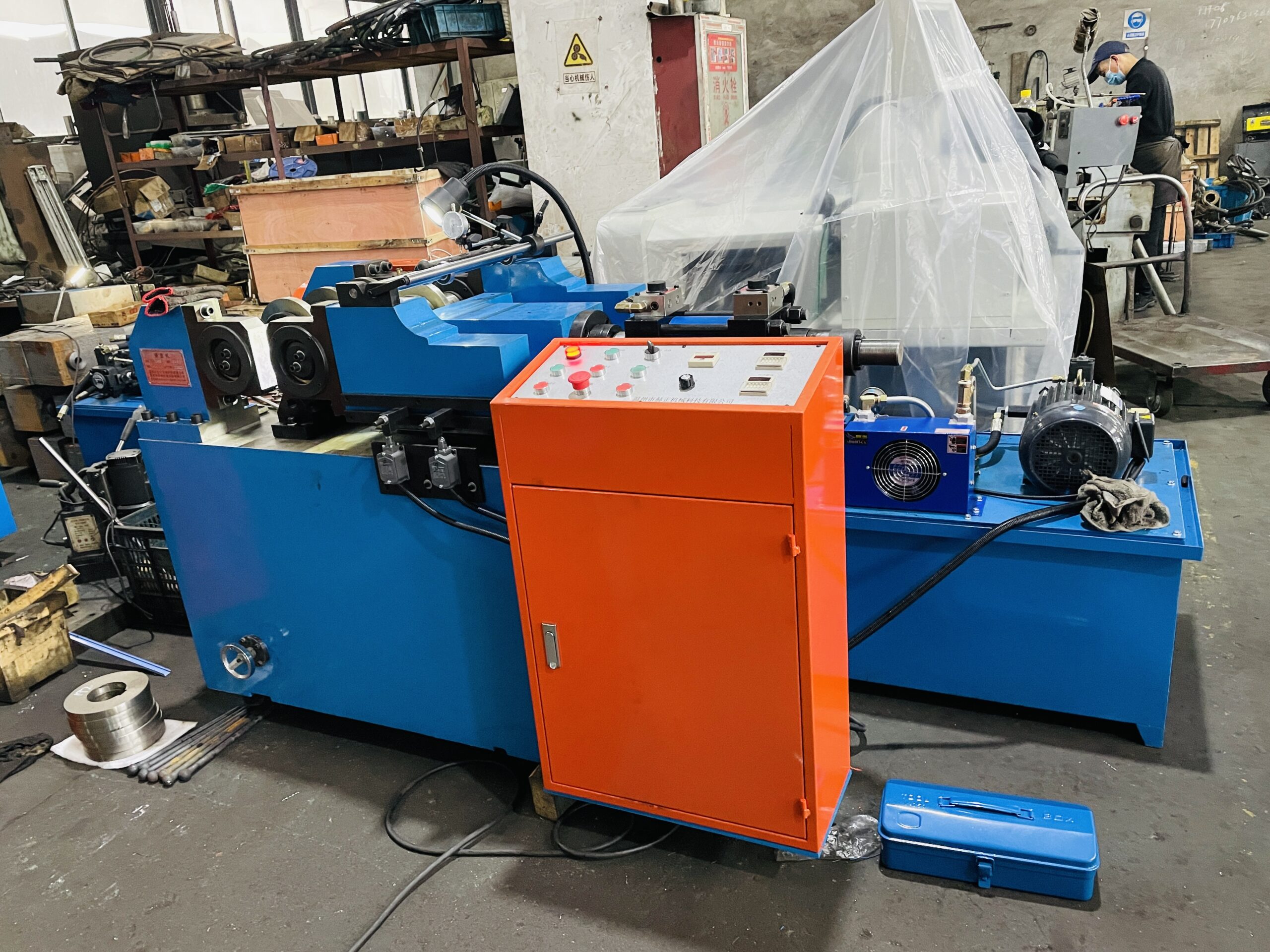
Projekta fotogrāfija apstiprina rullīšu tipa mašīnu, ceļveži un mērīšanas zona. Tas nepierāda konkrētu rullīšu skaitu, automātiska slēgta cikla vadība, ātrumu vai precizitāti.
Ieteicamais rullīšu iztaisnošanas process
1. Nosakiet apstiprināto variantu un posmu
Operators izvēlas precīzā kaluma recepti, garums, kāta diametrs, cietības stāvoklis un virsmas stāvoklis. Jauktu detaļu vai nepareizas ražošanas stadijas iekļūšana ruļļu komplektā ir novērsta.
2. Pārbaudiet ienākošo sagatavi
Daļas ar plaisām, krokas, smagi galvas bojājumi, pārmērīgs līkums vai izmēri ārpus apstiprinātā loga tiek atdalīti pirms iztaisnošanas. Iztaisnošana nav kalšanas defektu labošanas metode.
3. Orientējieties un virziet lodītes galvu
Ieejas vadotne notur tapas stabilitāti, vienlaikus ļaujot apstiprinātajai kāta zonai iekļūt ruļļos. Lodgalva un pāreja paliek ārpus kaitīgā līnijas kontakta. Ja daļā ietilpst dzīvokļi, to ietekme uz rotāciju un barošanu ir apstiprināta.
4. Izmantojiet apstiprināto veltņa iestatījumu
Ruļļa profils, šķērsošanas leņķis, sprauga/spiediens, vadotnes pozīcija un padeves ātrums tiek kontrolēti pēc receptes. Iestatījumam ir jārada pietiekama plastiskā korekcija kātā bez pārmērīgām diametra izmaiņām, pulēšana, ievilkums, temperatūras paaugstināšanās vai atlikušā stresa risks.

5. Mērīt, izmantojot saskaņoto atskaites punktu
Daļa tiek mērīta norādītajās stacijās un orientācijās. Atkarībā no zīmējuma, tā var būt mašīnas pārbaude, ārējais mērītājs, optiskais profils vai uz rotāciju balstīts palaišanas tests. Redzamais indikatora izvietojums fotoattēlā atbalsta mērījumu darbību, nav automātiska galīgās pārbaudes prasība.
6. Izlemiet piespēli, pārstrādāt vai noraidīt
Viena papildu caurlaide ir atļauta tikai tad, ja tā ir iekļauta apstiprinātajā receptē. Neierobežota atkārtota velmēšana var mainīt virsmas stāvokli, diametrs un atlikušais spriegums. Daļas, kas atrodas ārpus apstiprinātā loga, tiek ievietotas karantīnā inženiertehniskajai pārbaudei.
7. Pārbaudiet stāvokli, kā arī ģeometriju
Kvalitātes plānā var iekļaut virsmas pārbaudi, izmēru pārbaudes, magnētisko daļiņu vai citu plaisu pārbaude, cietības pārbaude un pakārtotās apstrādes/montāžas izmēģinājumi. Precīzas metodes seko materiālam, ražošanas posms un klienta rasējums.
Īsts Long Ball Stud iztaisnošanas video
Šis publiskais video ir saistīts ar oriģinālo garo lodveida tapas rakstu un parāda projekta rullīšu iztaisnošanas aprīkojumu. Tas atbalsta tikai redzamā procesa koncepciju. Tas nepierāda iepriekš teikto 0.2 mm rezultāts, 20-45 HRC diapazons, Indijas klients, ražošanas palielināšana vai klientu novērtējums.
Rullīšu iztaisnošana vai izmērītā punkta korekcija?
| Lēmuma faktors | Rullīšu iztaisnošana var būt priekšroka, kad | Punktu korekcijai var būt priekšroka, kad |
|---|---|---|
| Liekumu sadalījums | Izliekums ir sadalīts pa vienmērīgu kātu | Var izmērīt vienu vai vairākus lokalizētus augstākos punktus |
| Kontaktu zona | Ir atļauts pastāvīgs kāta kontakts | Ir atļautas tikai atlasītas atbalsta un preses zonas |
| Beigu ģeometrija | Galva un citas funkcijas var notīrīt roll/vadības sistēmu | Sarežģītie gali padara nepārtrauktu caurbraukšanu nedrošu |
| Virsma | Veltņa kontakts un jebkurš pulēšanas efekts ir pieņemams | Gatavām virsmām ir nepieciešami lokāli aizsargāti instrumenti |
| Mērīšana | Pietiek ar pārbaudi pirms/pēc vai parauga pārbaudes | Pēc katras korekcijas ir jāveic slēgta cikla mērījumi |
| Daļu maisījums | Stabils, lielāka apjoma ģimene | Mazāka tilpuma vai augsta maisījuma daļas ar īpašām receptēm |
Neviena no metodēm nav vispārēji “labākā”. Pētījuma paraugs var arī parādīt, ka iztaisnošana ir jāpārceļ uz agrāku ražošanas posmu, nevis jāpiespiež gatavā lodveida tapa, izmantojot kādu no šiem procesiem..
Galva, Pārejas un virsmas aizsardzība
| Risks | Kontrole |
|---|---|
| Bumbiņas virsmas iespiedums vai skrāpējums | Atbrīvojiet bumbu no darba ruļļiem un izmantojiet apstiprinātas vadotnes |
| Pārejas plaisa | Izslēdziet rādiusu no koncentrētas slodzes; pievienojiet nepieciešamo plaisu pārbaudi |
| Kāta ievilkums vai diametra maiņa | Match roll profilu, spiediens un virsmas stāvoklis; izmērīt pēc apstrādes |
| Plakans vai vītne noķer vadotni | Definējiet orientāciju/klīrensu un izmantojiet variantam raksturīgus instrumentus |
| Sacietējušā slāņa bojājums | Apstipriniet kontakta spriegumu un korekcijas ierobežojumu ražošanas līdzvērtīgiem paraugiem |
| Pārkaršana vai pārmērīga pulēšana | Ierobežojiet ātrumu/spiedienu/pārejas un uzraugiet saskaņoto stāvokli |
| Daļa iziet neprognozējami | Izmantojiet pozitīvas rokasgrāmatas, apsardze un droša savākšana |
Pārbaudes un pieņemšanas plāna paraugs
Reprezentatīvie paraugi
- īsākais izmantojamais veltņa kontakta garums un lielākā galvas un kāta attiecība;
- minimālais un maksimālais kāta diametrs;
- visi attiecīgie kalšanas un termiskās apstrādes nosacījumi;
- katrs dzīvoklis, konusveida, vītnes un gala konfigurācija;
- daļas reālajā ienākošā līkuma sadalījumā;
- vairākas partijas, kur kalšanas skala, cietība vai atspere var atšķirties.
Nepieciešamie pierādījumi
| Ieraksts | Pieņemšanas pierādījumi |
|---|---|
| Daļas identitāte | Zīmējuma pārskatīšana, variants, materiāls, posms un partija |
| Ienākošā ģeometrija | Raksturīgs, datum, pozīcijas un vērtības |
| Recepte | Ruļļi, ceļveži, sprauga/spiediens, leņķis, ātruma un caurlaides ierobežojums |
| Galīgā ģeometrija | Tāda pati definēta īpašība plus korelācija ar klientu |
| Izmēri | Kāta diametrs un funkcionālās īpašības paliek pielaides robežās |
| Virsma/pāreja | Apstiprināts vizuālās un plaisu pārbaudes rezultāts |
| Ražošanas izmēģinājums | Izmērītais cikls, ievārījumi, maiņa, pārbaude un pieejamība |
Pētījumā jāiekļauj daļas, kas atrodas netālu no paredzētā procesa robežas, ne tikai daži vienkārši paraugi.
Automatizācijas joma
| Līmenis | Tipisks apjoms |
|---|---|
| Rokasgrāmata | Operatora slodzes, palaiž apstiprināto caurlaidi un izkrauj pārbaudei |
| Asistēja | Ieplūdes/izplūdes atbalsts un vadīta savākšana |
| Automātiski | Atdalīšana, orientācija, ripināšana, mērīšana un rezultātu šķirošana |
| Izsekojama | Daļas/partijas identitāte, recepte, mērījumu un procesu ieraksti |
Automātiskā iekraušana ir atkarīga no tā, vai lodīšu galviņas sapinās, vai plakaniem vai konusiem ir nepieciešama orientācija un vai ir pieļaujama saskare ar virsmu. Automatizācija un izsekojamība ir pasūtītas darbības jomas, nevis pieņēmumi no mašīnas fotogrāfijas.
Kas nav universāls solījums
Pirms rasēšanas pārskatīšanas un parauga apstiprināšanas, šis risinājums nesola:
- 0.2 mm taisnums nenoteiktam raksturlielumam;
- viens procesa logs katrai 20–45 HRC daļai;
- piemērotība samontētiem lodveida savienojumiem vai pilnīgiem stieņiem;
- drošs veltņa kontakts uz gatavām bumbiņām, konusveida, diegi vai pārklājumi;
- viens rullīšu iestatījums visiem garumiem un diametriem;
- nulles plaisas, atzīmes, diametra izmaiņas vai atlikušā sprieguma ietekme;
- fiksēts cikla laiks, izlaides palielināšana vai izmaksu samazināšana;
- Indijas klienta rezultāts vai atsauksme bez autorizētiem ierakstiem.
Saistītās lietojumprogrammas
Pārskatiet mūsu Stiprinājumu un instrumentu iztaisnošanas risinājumi un Ball Stud iztaisnošanas mašīna blakus esošās lietojumprogrammas un aprīkojuma kontekstam. Ja detaļai ir stūres statnis vai samontēta stieņa funkcija, tam nepieciešams atsevišķs datu un funkcionālā riska pētījums.
Informācija, kas jānosūta priekšlikumam
Lielākā daļa garo lodveida tapu iztaisnošanas jautājumu notiek ātrāk, kad pircējs ierodas ar mašīnu izvēles rokasgrāmata vārpstām, caurules un profili jau izstrādāts un mērķa diapazons no cenu sadalījums iztaisnošanas mašīnām.
Nosūtiet zīmējumu un labojumu, reprezentatīviem paraugiem, lodītes/kāta/pārejas izmēri, plakanie/konusveida/vītņu detaļas, materiāls un termiskās apstrādes ceļš, precīzs ražošanas posms, virsmas stāvoklis, ienākošā līkuma sadalījums, gala raksturlielums un atskaites punkts, klientu mērītājs, aizliegtās saskares zonas, plaisu pārbaudes prasība, izvades mērķis un vēlamā ielādes metode.
Sazinieties ar StraighteningTech uz paraugu balstītam garās lodveida tapas iztaisnošanas pētījumam. Mēs noteiksim piemērotu procesa posmu, veltņa vai punktu korekcijas koncepcija, aizsargājamās zonas, mērīšanas metode un faktiskās detaļu saimes pieņemšanas pierādījumi.
Bieži uzdotie jautājumi
Vai lodveida tapa ir tāda pati kā stiprinājuma stienis?
Nē. Lodveida tapa ir sastāvdaļa lodveida savienojuma iekšpusē. Stienis ir lielāks stūres savienojums, kas parasti ietver lodveida savienojumus un regulēšanas savienojumu. Šis risinājums attiecas uz atsevišķām garajām lodveida tapu sagatavēm vai daļām.
Vai lodītes galva var iziet starp iztaisnošanas ruļļiem?
Nav pēc noklusējuma. Bumba un tās pāreja ir funkcionāla, ļoti noslogotas zonas. Instrumenti parasti tos notīra vai virza, kamēr apstiprinātais vienotais kāts nonāk ruļļos. Jebkurš tiešs kontakts prasa skaidru rasējuma apstiprinājumu un parauga validāciju.
Var rūdītas daļas 45 HRC ir jāiztaisno ar rullīti?
Iespējams, konkrētam materiālam, cietības profils, ģeometrija un ienākošais līkums, bet ar to skaitu vien nepietiek. Springback, lietas dziļums, pārejas stress, ir jāpārbauda plaisu risks un pieļaujamā saskare ar virsmu.
Ir 0.2 mm taisnuma vai izskrējiena prasība?
Skaitlis vien uz to nevar atbildēt. Zīmējumā jānosauc raksturlielums, kontrolēts garums, datum, mērījumu pozīcijas un novērtēšanas metode. Tad mašīnai un klienta mērinstrumentam ir nepieciešams korelācijas pētījums.
Kad tā vietā būtu jāapsver punktu korekcija?
Kad līkums ir lokalizēts, izmantojamais veltņa kontakta garums ir īss, sarežģītas funkcijas novērš drošu nepārtrauktu pārvietošanos vai pabeigtām virsmām ir nepieciešami selektīvi instrumenti un slēgta cikla mērījumi.
Tehniskās atsauces robeža
- ZF lodveida savienojumi: https://press.zf.com/press/en/media/media_2252.html
- ZF Stieņi: https://www.zf.com/products/en/cars/products_65853.html
- ZF stūres un šasijas daļas: https://aftermarket.zf.com/sg/aftermarket-portal/our-portfolio/passenger-cars/products/steering-and-chassis-parts/
- MOOG lodveida savienojumi: https://www.moogparts.com/en-eu/products/suspension/ball-joints.html
- Danieli iztaisnošanas mašīnas: https://www.danieli.com/en/products/products-processes-and-technologies/ingot-casting_26_12.htm
- Mair Research divu rullīšu iztaisnošanas mašīna: https://www.mair-research.com/en/two-roll-rightening-machine/
- MAE sagataves un pielietojumi: https://mae-group.com/en/workpieces-applications/
Šīs atsauces atbalsta lodveida savienojumu terminoloģiju, materiāla stāvokļa dažādība un vispārējie veltņu/spiediena iztaisnošanas principi. Tie nepierāda, ka cita piegādātāja darbība attiecas uz StraighteningTech konfigurāciju.