
Oil tubing and casing are not interchangeable with solid bars or drill pipe. They are long hollow OCTG products whose body, fal, upset or plain end, threaded connection, csatolás, internal surface and service history must remain inside one controlled process.
A reliable oil tubing and casing straightening solution must answer five questions before machine selection:
- Which tubing or casing family, méret, fal, fokozat, heat-treatment state and end finish is in scope?
- Is the part new production material or used pipe entering a maintenance and inspection route?
- How will body curvature be separated from ovality, local collapse, support sag, connection eccentricity and setup error?
- Which plain-body zones may contact rolls, supports or a press shoe, and which threads, couplings, upset ends and damaged areas are protected?
- How will the fully released pipe be remeasured, reinspected and traced after correction?

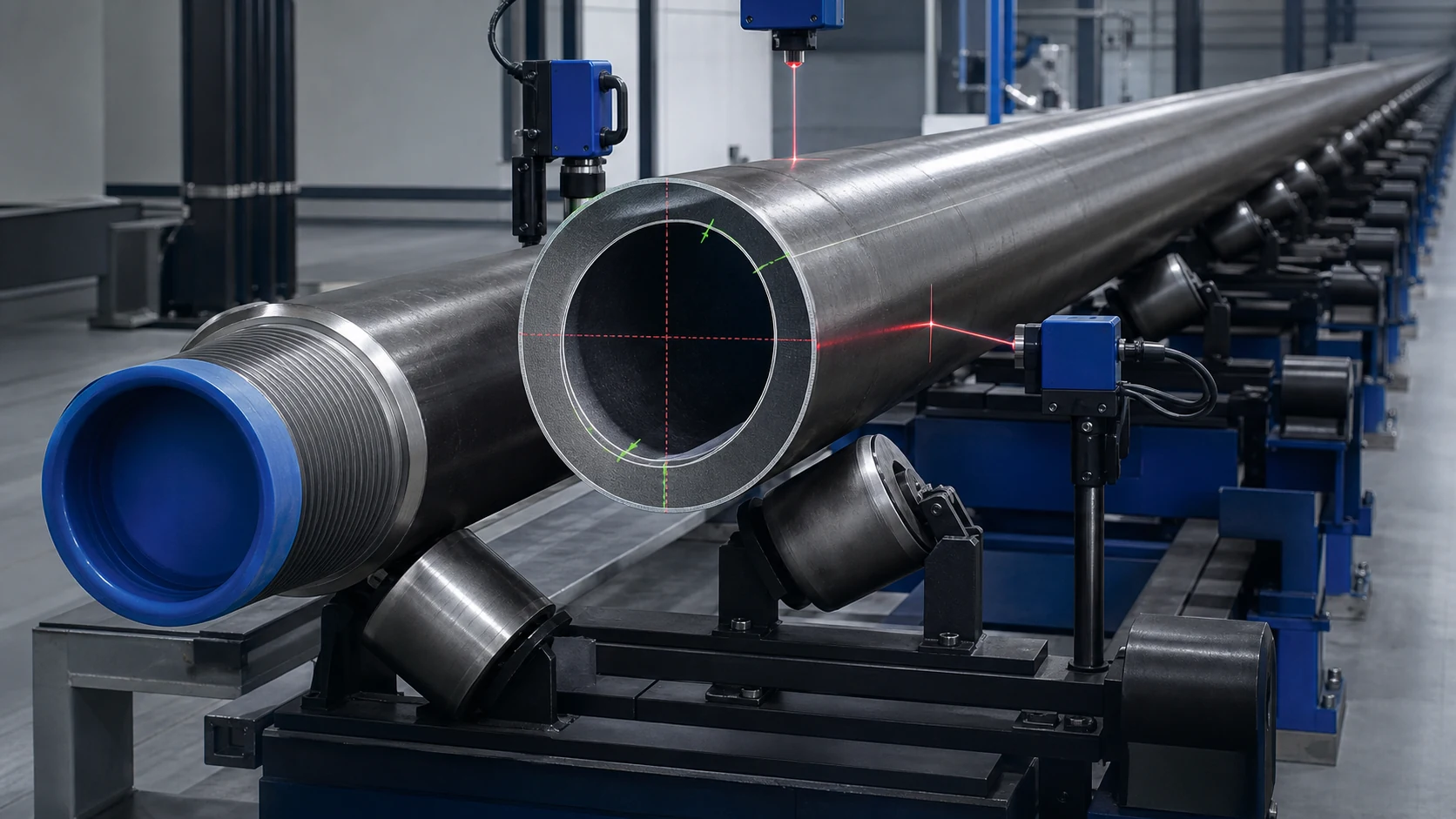
*Engineering concept illustration of a hollow oilfield tubular in a roller straightening and measurement line. It is not a customer-site photograph or performance claim. Actual roll geometry, támogatja, sensors and acceptance limits require the controlled pipe specification and representative sample tests.*
Define the Tubular Family Before Selecting Equipment
| Tubular Family | Main Difference | Route on This Page |
|---|---|---|
| Production tubing | Hollow pressure-containing product with controlled body and connection features | Primary scope; freeze grade, fal, end finish and process stage |
| Production casing | Larger family with different wall, connection and handling envelope | Primary scope; validate load, support and ovality limits separately |
| Used tubing or casing | Service, korrózió, wear and repair history may be uncertain | Inspection-first route only |
| Plain-end pipe | No finished threaded connection at the current stage | Contact map may be broader, subject to downstream machining stock |
| Upset or threaded-end pipe | Local stiffness and protected functional surfaces differ from the body | Keep transition, szál, váll, seal and coupling outside unapproved contact |
| Drill pipe or drill collar | Different connection, upset/tool-joint and drilling service duty | Use the dedicated drill-pipe route |
| Sucker rod | Solid cyclically loaded rod with forged pin ends | Use the sucker-rod solution |
| General seamless tube | May not be an OCTG product or use the same acceptance route | Use the seamless/thin-wall tube solution |
Boyu Petro publicly describes a dedicated equipment category for tubing, casing and related oilfield tubulars. Fives separately describes straighteners for thick- or thin-wall, welded or seamless, plain or upset tube and pipe. These sources support the equipment category, but they do not make one recipe valid for every OCTG family.
Freeze the Manufacturing or Maintenance Stage
Hőkezelés előtt
Correction may support the next operation, but later heat treatment can recreate distortion. The accepted value at this stage is not automatically the final released value.
Hőkezelés után, Before Final End Finishing
Fokozat, keménység, residual stress and remaining end-finishing stock become proposal inputs. Contact and overbend trials must use representative material condition.
Finished New Tubing or Casing
Finished connections, coupling state, bevonat, internal surface, identification and traceability must be protected. The straightener cannot treat a premium connection as a convenient clamping land.
Used Pipe From Service
Tisztítás, identity, service history and the applicable visual, dimensional and nondestructive inspection disposition come before force. Straightening changes geometry; it does not restore wall lost to corrosion or prove that a damaged connection is fit for reuse.
Build a Controlled Datum and Support Model
Long tubulars deflect under their own weight. A profile measured on changing support spacing is not a stable process input. The proposal should freeze:
- axial origin and pipe orientation;
- támogatások száma, térköz, height and contact material;
- overhang and conveyor transition behavior;
- measurement in a defined stationary or rotating condition;
- full-length body profile at controlled axial stations;
- outside diameter and ovality at required sections;
- wall-thickness or local-loss inputs when required by the inspection route;
- exclusion distances around upset transitions and connections;
- tisztaság, temperature and stabilization condition;
- repeatability after unloading, rotation and reclamping;
- correlation with the customer gauge and released inspection method.
Read shaft straightness vs runout vs TIR before naming the reported value. Centerline straightness, rotating outside-surface runout and local outside-diameter variation are related signals, not synonyms.
*Engineering concept illustration of controlled supports, centerline measurement and cross-section checks. It is not a prescribed gauge layout. Actual sensor tracks, ovality sections, wall checks and support spacing require the drawing, applicable specification and customer gauge correlation.*
Separate Bend From Cross-Section and Connection Error
| Observed Signal | Possible Cause | Required Route |
|---|---|---|
| Smooth long-wave centerline error repeated after reclamping | Global body bow | Candidate for validated roll or press correction |
| Sharp local direction change | Kink, impact or local collapse | Inspection and engineering review; do not average into global bow |
| Outside-surface runout changes strongly with clocking | Ovalitás, wall variation or eccentricity | Cross-section inspection before correction logic |
| Profile changes when support spacing changes | Self-weight sag or unstable handling | Freeze the support model and repeat measurement |
| High signal near an upset transition | Intended geometry, stiffness change or forming error | Feature-specific measurement and exclusion zone |
| Body profile is stable but thread axis or coupling appears misaligned | End-feature or connection problem | Inspect separately; body correction may not solve it |
| Bend coincides with corrosion, crack indication or wall loss | Material damage | Reject or route to the approved repair/inspection authority |
| Pipe is straight while drift, pressure or connection checks fail | Bore, fal, end finish or connection defect | Straightness acceptance cannot override the failed function |
Protect Connections, Walls and Surfaces
Default Protected or Review Zones
- external and internal thread forms;
- pecsét, váll, face and coupling functional surfaces;
- upset or swaged sections and body-to-upset transitions;
- identification and traceability marks;
- coating or specially treated surface without an approved contact trial;
- thin, locally worn or corroded wall;
- horpadás, kink, gouge, crack indication or repaired zone;
- areas containing accessories or features not represented in the machine recipe.
Potentially Approved Contact Zones
- cleaned plain-body lands with confirmed wall, outside diameter and surface condition;
- unfinished body stock before final surface treatment when the process plan allows it;
- broad rollers, saddles or replaceable inserts validated for contact pressure and marking;
- controlled support points selected away from transitions, connections and damage.
The protected-zone map belongs to a specific tubular family and revision. A support that is safe for one tubing size may sit on a coupling, upset transition or thin-wall section on another.
Choose Roller or Point-Press Correction From the Error Map
Multi-Roll Straightening for Production Flow
Roller straightening can suit repeatable long-wave curvature and continuous production when the body provides a qualified contact track. Fives confirms industrial tube straighteners are configured around wall condition, seam state and end geometry. A production-line proposal should therefore define:
- roll arrangement and adjustment range for each approved family;
- entry and exit support control;
- end detection and automatic connection protection;
- surface-marking and cross-section trials;
- recipe control by grade, wall and process stage;
- post-roll released geometry and ovality checks;
- reject routing when the signal is not a correctable body bend.
Point-Press Straightening for Localized or Maintenance Work
New Tech Systems publicly describes an oilfield pipe straightener with conveyors, pipe rotation and controlled hydraulic correction. That supports a maintenance-oriented point-press architecture. It does not establish the force, span or acceptance limit for this solution.
A point-press route needs:
- two stable reaction supports and one approved press zone;
- a complete support/reaction/load path;
- bounded force, displacement and overbend;
- rotational indexing under a controlled support condition;
- fal, ovality and surface checks after each bounded correction;
- fully released remeasurement before another iteration.
Read press straightening vs roller straightening for the general method comparison, then apply the tubing/casing connection and cross-section gates.

*Engineering concept illustration of a protected plain-body press point and supported hollow casing. It is not a universal machine layout. Actual support span, shoe radius, erő, overbend and iteration limits require sample trials and released inspection.*
Use an Inspection Gate Before and After Correction
API identifies Specification 5CT as the casing and tubing specification and highlights controlled variables including grade grouping, special end-finish threads, material records and NDE personnel requirements. The customer must state the applicable edition, product level, purchaser supplements and company procedure; this page does not replace those documents.
The incoming gate should confirm, as applicable:
- product identity, fokozat, méret, wall and heat-treatment state;
- new production or used-service status;
- end finish, coupling and protector condition;
- cleaning and visual inspection disposition;
- outside diameter, ovális, wall and drift status;
- required NDT status and qualified personnel route;
- bevonat, korrózió, wear, horpadás, gouge and prior repair status;
- traceability and the allowed correction stage.
The outgoing gate should repeat the specified geometry under the released support condition and then complete the required surface, dimensional, connection, furat, pressure or NDT checks. A green straightness result must not override an NOK wall, drift, szál, seal or inspection result.
Build a Released-Part Closed Loop
- Identify the tubing/casing family and controlled revision.
- Confirm process stage, service status and inspection disposition.
- Clean the part and protect the connection, coupling and sensitive surface.
- Load it on the frozen support and handling model.
- Measure full-length geometry and required cross sections.
- Classify bow, ovális, kink, end-feature error, damage and setup error separately.
- Select roller, point press, reject or engineering-review route.
- Apply only the bounded correction assigned to an approved body zone.
- Fully release, stabilize and remeasure under the same datum condition.
- Repeat only within force, elmozdulás, iteration, wall and surface limits.
- Complete the required post-process inspection.
- Store the geometry result, quality disposition and traceability record.
Configure the Cell Around the Real Part Family
| Cell Funkció | Tubing and Casing Requirement |
|---|---|
| Azonosítás | Family, méret, fal, fokozat, end finish, process stage and traceability |
| Kezelés | Long-bed conveyors, controlled supports, rotation and protected connections |
| Mérés | Full-length centerline plus required OD, ovális, fal, end and bore checks |
| Classification | Íj, kink, ovális, összeomlás, connection error, damage and setup error |
| Javítás | Qualified roller recipe or bounded point-press load path |
| Védelem | Szálak, seals, vállak, faces, couplings, upset transitions and coatings |
| Ellenőrzés | Fully released remeasurement plus applicable functional and inspection checks |
| Adat | Before/after profile, receptet, force/displacement, inspection status and result |
Proposal Inputs We Need
Send the following before equipment selection:
- controlled drawings or product specification;
- tubing/casing family list and annual or shift mix;
- outside diameter, fal, hossz, grade and heat-treatment state;
- plain, upset or threaded end details and coupling state;
- new-production or used-service route;
- incoming bend distribution and known ovality, dent or wall issues;
- permitted contact zones and surface/coating requirements;
- required straightness, kifutás, ovális, drift, connection and inspection outputs;
- applicable standard edition and purchaser supplements;
- upstream/downstream operations and line takt requirement;
- képviselő jó, marginal and reject samples;
- ügyfélmérő, report format and traceability interface.
Sample-Test Acceptance Before Production Release
The sample trial should represent the real family envelope, not one convenient pipe. It should verify measurement repeatability, support influence, connection protection, roller or press contact, felületi állapot, ovality response, visszaugrás, released geometry and downstream inspection correlation.
Használja a straightening sample test and acceptance guide to freeze the evidence package before production release.
Engineering Boundary
Straightening can correct an approved geometric error in suitable material. It does not repair a crack, replace lost wall, remove a dent or kink by definition, restore a rejected thread or seal, prove pressure integrity, or qualify used pipe for service without the applicable inspection authority.
Tonnage, roll geometry, támasztávolság, pontosság, ciklusidő, marking limit and iteration count are proposal outputs. They must come from the controlled tubular family, rajz, anyagi állapot, applicable specification, representative samples and gauge correlation—not from a generic machine brochure.
Request an Oil Tubing and Casing Straightening Review
Send the family table, rajzokat, folyamat szakaszában, inspection route and representative samples. We will return a proposed datum and support model, protected-zone map, roller-versus-press decision, measurement plan, sample-test matrix and equipment concept for review.