
A shift fork shaft — also called a shift rail — is the hardened slender shaft on which gear-shift forks slide inside a manual gearbox or transfer case. The forks straddle the synchronizer grooves; the shaft locates the forks, carries selector force and often defines fork position with grooves, detent notches, cross-drillings and circlip seats. Because the fork follows the shaft, a bent rail turns every shift into a fight: uneven pad engagement, jumping out of gear, and accelerated synchronizer wear. The shaft is a small, cheap-looking part whose straightness quietly governs the feel of the whole transmission.
One boundary statement first: this page is about straightening the shaft, in its manufacturing chain. Search results for bent shift forks are dominated by a different question — whether a fork’s own claw legs can be re-aligned after damage, a workshop and forum topic. The fork body is a forked lever, not a slender rotating part, and its correction is not what a shaft straightening line does. Equipment builders that publish workpiece lists for automatic straightening machines — KOKUSAI among them — list shift fork shafts as shaft-family parts, which is the correct classification and the subject here.
Five questions frame the solution:
- Is the part a plain hardened rail, a rail with detent grooves and cross-drillings, or a combined shift shaft with spline and lever features?
- At which stage is correction planned — after hardening before grinding, or after finish machining?
- Which datum reproduces the transmission’s own mounting: fini jounal, the fork sliding sections, or centers?
- What hardness and residual-stress state limits correction force, and how much springback is expected?
- How will released runout be verified together with groove position and surface condition?

*Jeni konsèp ilistrasyon: hardened shift rails staged for straightness inspection. Se pa yon foto kliyan-sit. Contact rules, force limits and machine configuration follow drawings and sample tests.*
What the Search Results Show — and Don’t
The visible results for shift fork topics are rider and mechanic forums asking whether a fork is bent and what replacement costs, plus parts catalogs listing fork and shaft assemblies. There is essentially no manufacturing-side content about how these shafts are straightened in production. Meanwhile the workpiece lists published by automatic-straightening machine builders include shift fork shafts alongside camshafts, motor shafts and gear shafts — confirming a production process need that the open web simply does not document. That absence is the reason this page exists.
Shaft Families Inside the Gearbox
| Family | Fonksyon | Straightening Consideration |
|---|---|---|
| Plain shift rail (fè tèt di toujou, tè) | Carries and locates sliding forks | Classic hardened slender shaft; correction after hardening, before final grinding |
| Rail with detent grooves and cross-drillings | Adds detent ball seats and oil passages | Grooves and drillings are prohibited contact zones and stress raisers |
| Combined shift shaft with spline and lever | Input shaft actuating the rail system | Spline, lever seat and return-pin features restrict rotation datum and press zones |
| Fork guide pins and small rails (motorcycle) | Compact transmissions with narrow packaging | High slenderness; handling distortion is significant |
The families share hardened slender-shaft mechanics, so the process logic transfers from better-documented neighbours: la gearbox shaft, la small motor worm shaft ak la automatic ejector pin solutions all cover adjacent slenderness-and-hardness territory.
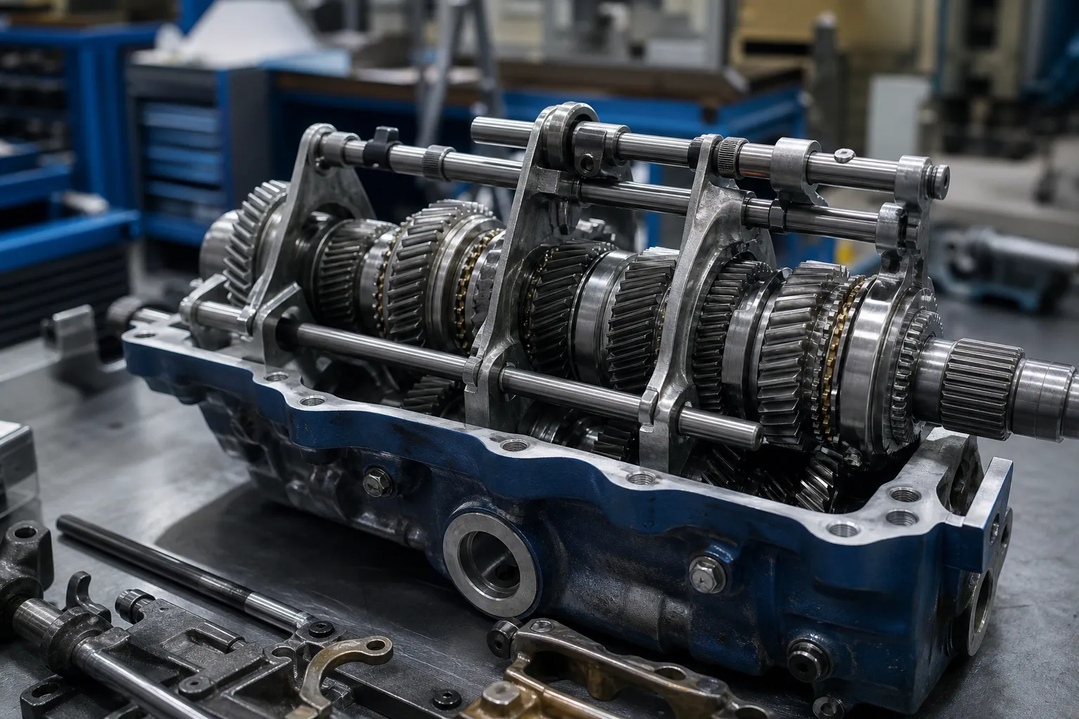
*Jeni konsèp ilistrasyon: forks straddling synchronizer grooves on their rails inside gearbox internals — the assembly context that makes rail straightness a shifting-quality parameter. Fork design and synchronizer details follow the transmission.*
Define the Datum Chain
A shift rail is measured the way any stepped or featured shaft is: rotate it in a qualified setup and read radial runout at defined stations. The datum question — centers, fini jounal, or the fork sliding sections — follows the same logic as the measuring datum selection guide for stepped shafts: the reference must reproduce how the transmission itself supports the part, or the runout number will not predict shifting behavior. Groove-bottom runout and journal runout can disagree, and only one of them matches the customer’s gauge.
Two diagnostic separations protect the process from chasing the wrong error:
- Bend vs form. Local out-of-round on a sliding section reads as runout in rotation but is a grinding issue, not a press issue — the roundness vs bend diagnosis applies directly.
- Global bow vs local jog. A rail bent at a groove and a rail bowed along its whole length need different press points; a single mid-span reading cannot tell them apart, which is the case for multi-station measurement as described in the LVDT multipoint measurement guide.

*Jeni konsèp ilistrasyon: multi-station runout measurement on a grooved rail between centers. Sensor position, groove masks and support definition belong in the measurement specification.*
Glase Etap Pwosesis la
| Etap | Opportunity | Risk |
|---|---|---|
| After turning, before hardening | Protect hardening furnace loading and stock distribution | Correction is undone by quench distortion |
| Apre vin di, anvan fanm k'ap pile | The main window: recover quench distortion with full grinding stock | Crack initiation at grooves and drillings; strong springback |
| Apre fini fanm k'ap pile | Salvage within final tolerance only | Functional surfaces closed to contact; limited evidence base |
Hardened rails bring the material behavior of every quenched slender part: springback that is large, batch-dependent and unforgiving of loaded readings, plus a narrowing margin under repeated reverse loading from the Bauschinger effect. The material-side staging logic is shared with the redresman apre tretman chalè gid; what follows is the same physics on a smaller, more featured part.
A practical consequence of that batch dependence: correction recipes should be validated per hardening lot, not per part number alone. Two lots of the same rail through the same furnace can present different springback for the same press increment, and a recipe tuned on lot one will over- or under-correct lot two. Recording force-displacement response per lot — not just final runout — is what separates a stable process from a line that periodically needs an operator’s intervention for reasons nobody can reconstruct afterwards.
Correct the Axis, Protect the Features
Point-press correction — the measure-support-press-release loop of the point-press straightening process — is the default mechanism, applied on plain journal or sliding sections:
- Approved zones: plain ground sections with stock remaining; surfaces clear of grooves, drillings and seats.
- Prohibited zones: detent grooves and groove run-outs (stress concentration), cross-drilled oil holes, circlip seats, threads and spline features, finished sliding surfaces without protected tooling.
- Conditional: zones near a groove need the press point set back far enough that bending, not local denting, does the work.
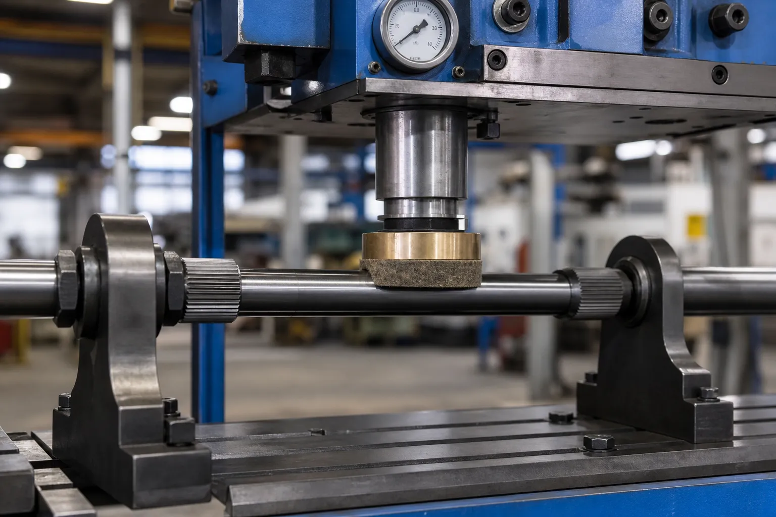
*Jeni konsèp ilistrasyon: correction on a plain section with grooved zones clear of supports and press tooling. The image does not authorize contact points for a specific rail design.*
Closed-Loop Process
- Load the recipe: rail designation, materyèl, dite, stage and drawing revision.
- Inspect the part: groove edges, twou lwil oliv, thread condition, handling damage.
- Qualify the datum setup: centers or end-journal supports, seating repeatability.
- Build the multi-station bend map with groove positions masked correctly.
- Classify: global bow, local jog at a feature, form error or damage.
- Select the press point on an approved section.
- Apply incremental correction with force and displacement ceilings.
- Release fully, rotate and re-measure the complete map.
- Inspect contact marks, groove edges and surface condition.
- Record maps, forces and disposition for traceability.
Automating the Loop
Shift rails are produced in volumes that suit the automated version of this loop — load, vire, mezi, calculate, peze, lage, re-measure, sort — because the part family is narrow and the cycle is short. The architecture of such machines, and where the engineering decisions actually live, is covered in the ki jan otomatik arbr redresman travay gid. The part-specific work — datum plan, groove masks, kontak kat jeyografik, correction envelope — is exactly what this page’s proposal checklist collects.
Common Failure Modes
The recurring mistakes: pressing over or beside a groove and cracking the run-out; judging correction on the loaded indicator instead of the released map; straightening before hardening and re-inheriting quench distortion; letting groove-bottom runout be measured with a probe ball wider than the groove so the reading mixes form with axis; and handling finished rails in bulk bins that bend more parts than the press corrected. All five are process-definition errors, not machine limits.
Done obligatwa pou yon pwopozisyon teknik
- rail drawing with all diameters, longè, grooves and drillings;
- spesifikasyon materyèl, hardness and heat-treatment method;
- process chain and intended straightening stage;
- incoming runout distribution and rejection rate;
- acceptance criterion: TIR limit and measurement stations;
- customer or transmission gauge definition (done, sipò, masking);
- prohibited contact zones marked on the drawing;
- grinding allowance remaining after correction;
- diameter and length range across the rail family;
- lot sizes and cycle-time expectations;
- representative bent samples for correction trials.
Kesyon yo poze souvan
Can a bent shift fork shaft be straightened?
In manufacturing, hardened shift rails are point-press corrected after hardening and before final grinding, the same staging used for other hardened slender shafts. Feasibility for a specific rail depends on hardness, feature layout and bend shape, established with samples.
Is this about straightening bent shift forks?
Non. The fork is a forked lever; forum threads about bent fork claws are a repair topic. What a straightening line processes is the fork shaft or rail the forks ride on — a rotating-family part with journals and grooves.
Where is the press point chosen on a grooved rail?
On plain sections with grinding stock remaining, set back from groove run-outs, circlip seats and oil holes. The contact map is part-specific and follows the drawing, not a general rule.
Why does groove runout matter separately from journal runout?
The groove positions the fork; the journals position the shaft. A rail can be straight on its journals and still locate a fork off-axis if a groove-related feature is displaced, so the measurement plan tracks both rather than one summary TIR.
How much springback should be expected?
More than in soft stock, and it varies by batch and material condition. That is why the loop ends with a fully released re-measurement instead of trusting the loaded reading — the reasoning in the loaded vs released measurement guide.
How does rail straightness show up in the finished transmission?
Through the fork. A bent rail tilts or offsets the fork pads relative to the synchronizer groove, so engagement force distributes unevenly, detent positions drift, and shifting feel deteriorates before any dimension on a fork measurement would flag it. That is why transmission builders treat rail runout as a functional characteristic, not a cosmetic one, and why the acceptance is tied to the datum the gearbox actually uses.
Send the Rail, Not the Symptom
We build shift fork shaft straightening solutions around the rail as a hardened, featured, arbr mens: a datum plan that reproduces the transmission’s supports, multi-station bend mapping with grooves masked, a contact map that keeps every groove, hole and seat out of the load path, and released verification with grinding allowance confirmed. Send the rail drawing, dite ak etap pwosesis, incoming runout data and representative samples, and we will define the measurement strategy, correction envelope and acceptance plan for your gearbox line.