
Hammaspyörän akseli on pyörivä voimansiirron komponentti, jossa on integroidut hammaspyörän hampaat - kannen, kierre- tai kartiohammaspyörä — yhdessä tappien kanssa, splainit, kierteet ja olkapäät yhdellä akselilla. Sen suoruusspesifikaatio on määritelty tälle akselille: tappien ja vaihteiston sylinterien on pyörittävä yhteisen linjan ympäri indikaattorin kokonaislukeman sisällä (TIR) laakerin käyttöiän asettama raja, vaihteistoverkon laatu ja akselin nopeus. Hammaspyörän akselin oikaisu tarkoittaa siis hammastetun komponentin pyörimisakselin palauttamista – täysin eri ongelma kuin hammastangon litistäminen, ja ongelma vakiintuneissa mittaus- ja korjausmenetelmissä.
Vaihteen akselin oikaisuratkaisun on vastattava viiteen kysymykseen ennen kuin laite valitaan:
- Mikä määrittää mittausakselin — päiväkirjat, keskipisteet tai uran päähalkaisija – ja heijastaako mittaus koottua laakerijärjestelyä?
- Onko poikkeama yksitasoinen keula, paikallinen mutka olkapäässä, kierre, tai yhdistelmä - ja missä on todellinen kohokohta?
- Mikä on materiaalin ja lämpökäsittelyn tila – läpikarkaistu, hiiltynyt ja sammutettu, induktiokarkaistut tapit - ja mitkä korjausreitit on hyväksytty sille?
- Onko hiomavarastoa vielä saatavilla, ja on korjaus, jonka tarkoituksena on palauttaa varaston jakautuminen tai lopullinen geometria?
- Miten geometria vapautuu, hampaan kyljen eheys ja pitkän aikavälin vakaus on tarkistettava?
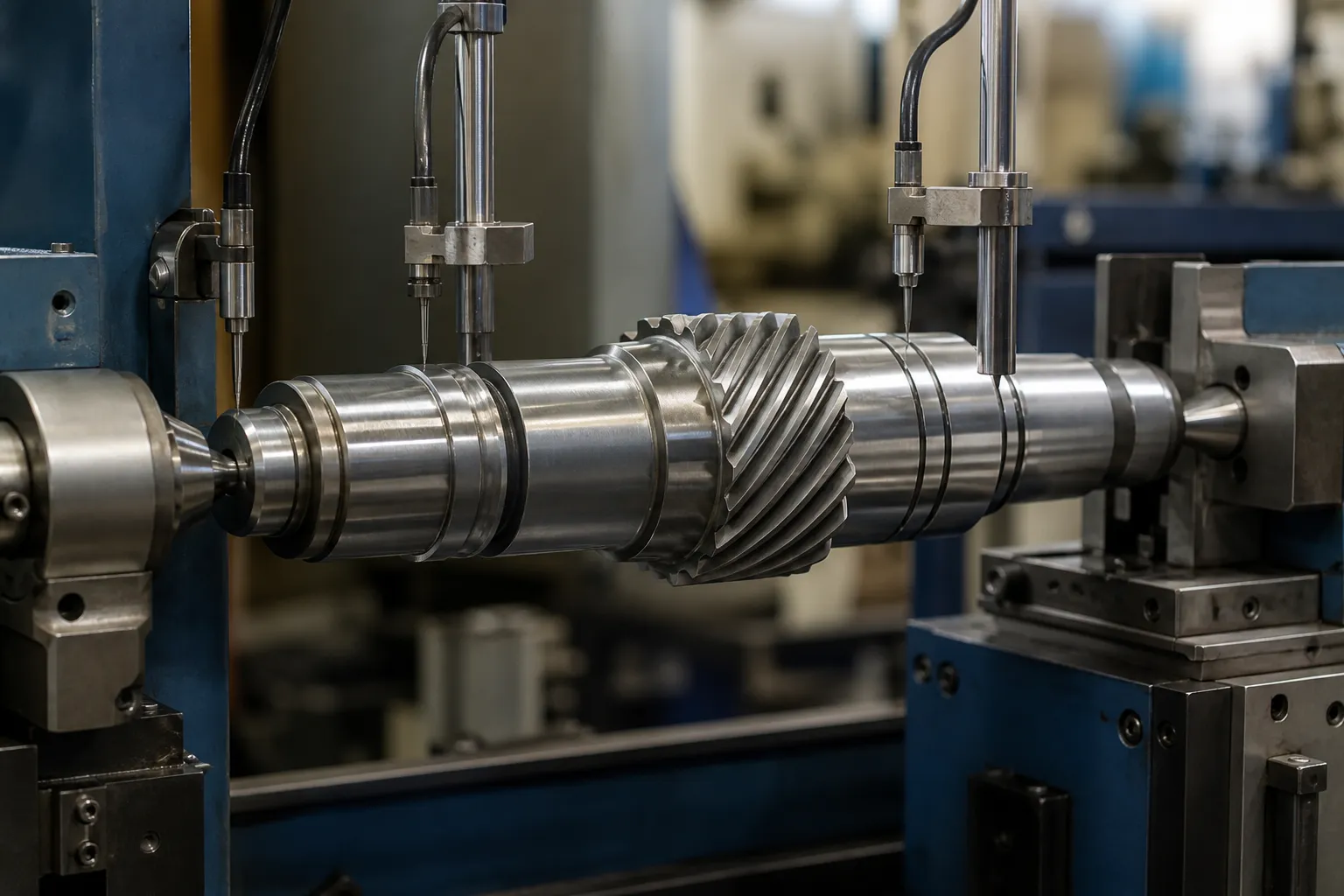
*Suunnittelukonseptin kuva: vaihdeakseli, joka on tuettu keskusten väliin koettimilla tapeissa korjaustutkimuksen aikana. Ei asiakkaan sivuston valokuva. Päivämäärän valinta, voimaasennot ja hyväksymisrajat edellyttävät piirustusta ja edustavia näyteosia.*
Hammaspyörän akseli vs. hammaspyöräteline: Kaksi eri ongelmaa
Tämä sivusto kattaa jo teollinen hammastankojen oikaisu, ja kaksi työkappaletta sekoitetaan usein, koska molemmissa on hammaspyörän hampaat. Heillä ei ole lähes mitään teknistä sisältöä:
| Vaihdeteline | Vaihteen akseli | |
|---|---|---|
| Toiminto | Muuntaa kierron lineaariseksi liikkeeksi; hammastettu suora tanko | Siirtää vääntömomentin pyörivien akselien välillä; hammastettu sylinterimäinen osa |
| Suoruuden määritelmä | Vertailupinnan tasaisuus ja suoruus yhdessä tasossa; jakoviivan tasaisuus | Pyörimisakselin poikkeama: TIR mitattuna kehän ympäriltä määritellyissä osissa |
| Ensisijainen mittaus | Lineaarinen - suoraviivainen, pintalevy, laserlinja, pituussuuntainen näytteenotto | Pyörivä – osa rullataan keskipisteiden välissä tai tappien päällä, kellotaulu tai elektroniset anturit, mutkakartta |
| Vika, jos se on vääntynyt | Sidonta, hampaiden epätasainen tarttuminen, paikannusvirhe | Epätasapaino, tärinää, laakerin ja tiivisteen vauriot, vaihteistoverkon kohdistusvirhe, väsymys |
| Tyypillinen korjaus | Puristus litteässä tasossa; joskus venytys- tai tasoitusprosesseja pitkille telineille | Piste-painalluksen korjaus kartoitetun huippupisteen kohdalla, valikoiva kiinnitys, rajoitetut lämpömenetelmät |
Teline korjataan tasossa; hammaspyörän akselia korjataan akselin ympäri. Mittaussanasto, kalusteet, koneet ja hyväksymiskriteerit ovat kaikki erilaisia, Siksi näitä kahta aihetta käsitellään erillisillä sivuilla. Jos työkappale on pitkä hammastanko, joka osuu hammaspyörään siirtääkseen kuormaa lineaarisesti, telinesivua sovelletaan. Jos se on akseli, jossa on hammaspyörä, joka pyörii laakereissa, lue eteenpäin.
Anatomia ja mistä vääristymät tulevat
Listaa ominaisuudet, jotka osallistuvat peruspisteketjuun ja jännitysjärjestelmään:
- laakeritapit — ensisijainen toimintaakseli;
- vaihdesegmentit: kierrehampaat, vaihdepinnan leveys, nousun ja juuren geometria;
- splainit, kiilaurat, langat, kartiot ja kytkentäominaisuudet;
- hartiat, lukitusrenkaan urat, poikkiporaukset ja öljyreiät;
- keskuksia tai väliaikaisia prosessin peruspisteitä;
- hiontamassa osittain ja prosessivaiheittain.
Hammaspyörän akselit taipuvat klassisista akselisyistä, dokumentoitu korjauskirjallisuudessa: mekaaninen ylikuormitus käsittelyn tai asennuksen aikana; epäsymmetrinen koneistus, joka vähentää sisäistä jännitystä epätasaisesti; lämpökäsittely, jossa hiiltyneen tai läpikarkaistun akselin sammuttaminen tuo lähes aina keulan; ja voimakkaat kutistus- tai puristussovitukset, jotka taivuttavat alun perin suoran akselin pinotukseksi. Varsinkin vaihteiston akseleilla, hobbing ja parranajo jättävät jäännösjännitystä hammastettuihin osiin, ja yhden takin lämpökäsittelyn jälkeinen hionta voi lievittää stressiä ja siirtää toista osaa - korjauspisteellä prosessissa on yhtä suuri merkitys kuin itse korjauksella.
Mittaa ensin: Bend Survey -kartta

Korjaustekninen käytäntö, jossa taivutettu akseli kartoitetaan ennen kosketusta, koskee täysin hammaspyörän akseleita, ja tuotantokoneet automatisoivat sen:
- Tue akselia keskusten välissä tai sen tappien päällä ja varmista, että tuet lukevat nollarunkoa – tukivirhe turmelee koko kartan.
- Merkitse kiertoviittaus; tallentaa TIR tasaisin välein olevilla aksiaalisilla asemilla, muuntamalla taipumaan (puolet TIR:stä) ja kellokulma kussakin.
- Lue kartta: yksi hallitseva huippukohta tasaisella kulmalla osoittaa yksinkertaista jousta; vaihteleva kulma pituussuunnassa osoittaa useita mutkia tai kiertymiä; vaikein tapaus on yhdistetty taivutus ja kierre.
- Etsi todellinen kohokohta asemien välillä – maksimi on siellä, missä trendi sanoo, ei välttämättä sinne, missä luotain sattui istumaan.
- Toista kartta jokaisen korjausjakson jälkeen ja lopussa tarkastuspöytäkirjana.
Tämän vaiheen sisällä on kaksi vaihdekohtaista ansaa. Ensimmäinen, datumin valinta: porrastetulla akselilla oikea perusketju on yleensä tapit, ei keskipisteitä - varsi voi lukea suoraan keskipisteistä ja kumartua lehtiin, ja laakerit eivät välitä keskuksista. Valintasäännöt on kuvattu yksityiskohtaisesti mittauspisteen valinta porrastetuille akseleille. Toinen, hampaan kylkivirhe vs. taipuminen: jako-sylinterin juoksu, joka on mitattu tapeilla tai vaihteistotarkistuksella, on erotettava akselin akselin juoksusta, tai hampaan valmistusvirhe "käsitellään" taivuttamalla akselia. Tässä käsitellään yleistä diagnostiikkalogiikkaa muotovirheen ja taivutuksen erottamiseksi pyöreys vs. mutka pyörivässä mittauksessa.
Korjausreitit
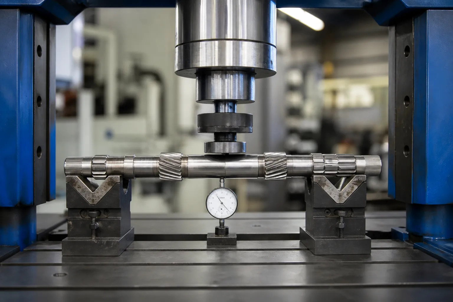
Mekaaninen pisteen puristus — ensisijainen reitti
Kartta kädessä, akseli on asetettu korkein kohta ylöspäin, tuettu lähelle mutkaa, ja ladattu pehmustetulla painimella samalla kun anturi tarkkailee jännitteistä taipumaa. Työskentele pienin vedoin ja hyväksy palautus: tavoitteena on vähiten korjauksia suvaitsevaisuuteen, koska jokainen muovisykli lisää jäännösjännitystä. Tuotantokoneissa tämä silmukka - kartta, paina, re-map – toimii automaattisesti osaperhekohtaisesti opitulla palautuskompensaatiolla. Manuaalisen akselin oikaisun askarteluosasta tulee ohjainparametri; fysiikka ei muutu.
Peening – Paikkoihin, joissa painaminen ei saavuta
Koveran puolen hallittu pisto- tai neulakuivistus puristaa pintakuituja ja kasvattaa niitä hieman, vetämällä akselia suoraan kohti. Hammaspyörän akseleissa peening on hieno trimmaustyökalu: se korjaa pienet jäännökset painamisen jälkeen, ja se toimii paikoissa, joita pässi ei voi ladata – hartioiden vieressä, lähellä hammastettuja osia – ilman hampaiden murtumisvaaraa. Se on hidasta korjausta kohti ja harvoin ensisijainen reitti.
Pistelämpö — rajoitettu karkaistuihin hammaspyörien akseleihin
Pienen vyöhykkeen pistelämmitys paikallisen vetojännityksen luomiseksi jäähdytyksessä on laillinen oikaisumenetelmä matalalla- ja keskihiiliset akselit karkaisemattomassa kunnossa. Hiilivedessä, läpikarkaistuja tai induktiokarkaistuja vaihteistoakseleita on voimakkaasti rajoitettu tai kielletty: lämpövaikutusalue voi pehmentää tai kovettaa uudelleen paikallista materiaalia, luo kovia kohtia ja mikrohalkeamia juuri sinne, missä hampaiden ja päivälehtien väsymys kuluu, ja jätä kohouma, joka on poistettava ennen kuin pinta menee laakeriin tai tiivisteeseen. Missä lämpömenetelmiä ylipäänsä harkitaan, ne kuuluvat metallurgin hyväksymään korjausmenettelyyn, ei tuotannon korjaussykliin. Materiaalisäännöt on täsmennetty suoristus lämpökäsittelyn jälkeen.
Mitä hammaspyörän akselin puristaminen ei koskaan sisällä
Kuormitukset kohdistuvat tukien väliin tappi- tai akseli-runko-osiin – ei koskaan hammaspyörän hampaisiin. Hammassegmentin painaminen vaarantaa hampaan muodonmuutoksen, jota mikään oikaisu ei voi peruuttaa, ja sileissä akseleissa käytettyä telaoikaisua ei käytetä hampaiden päälle. Spline-osuudet noudattavat omia sääntöjään, katettu meidän ura-akselin oikaisuratkaisu; akseliperheet mitattiin ja korjattiin vaihteiston sisällä – syöttö, ulostulo- ja väliakselit usean päivän hyväksymislogiikallaan – käsitellään erikseen vaihteiston akselin oikaisuratkaisu.
Hyväksymiskriteerit

Akselin korjauskäytäntö antaa käyttökelpoisen lähtötilanteen: noin 0.001 pituuden jalkaa kohti (0.083 mm/m) yleisiin pyöriviin laitteisiin, kiristäen kohti 0.0005 sisään (0.013 mm) nopeille monivaiheisille koneille yhteensä missä tahansa kohdassa. Hammaspyörän akseleille piirustus hallitsee, ja toleranssiluokka seuraa hakemusta: hidas nopeus, matalan toleranssin hammaspyörän akselissa on leveämpi ikkuna kuin korkealla kierrosluvulla, lähietäisyys hammaspyörä. Hyväksymisjärjestyksen tulee olla:
- lopullinen kartoituskartta kaikilla asemilla, määritellyn TIR:n sisällä;
- vaihteiston laadun tarkastukset — hampaiden kosketus, juoksu tappien yli, kierteen kohdistus — korjaus ei muutu;
- materiaalin kunnon mukainen halkeamien havaitseminen kaikkien korjausten jälkeen;
- tarkastus viimeisen hionta- tai viimeistelytoimenpiteen jälkeen, ei vain suoristuksen jälkeen;
- vakauden vahvistus, jos sovellus on kriittinen: mittaa uudelleen seisontajakson tai lämpötilajakson jälkeen, jos prosessiikkuna ei ole jo osoittanut stabiilisuutta.
Viimeinen kohta on kaiken akselin oikaisun rehellinen heikkous: korjaus, joka vain asettaa uuden jännityksen vanhaa mutkaa vasten, voi lukea suoraan tänään ja ajautua käyttöön. Tästä syystä korjausten määrä on rajoitettu, miksi kartta toistetaan viimeistelyn jälkeen, ja miksi vetojen määrä toleranssiin on itsessään prosessilaadun signaali – periaatteet, joita sovelletaan koko rivin laajuisesti automaattinen akselin oikaisu.
Yleiset sudenkuopat
- Kartoitus väärään datapisteeseen. Keskipisteet, jotka eivät enää edusta laakerin akselia, tuottavat kartan, jota ei voida korjata toimivaksi akseliksi.
- Painaminen asemalla kohokohdan sijaan. Suurin taipuma on yleensä mittausasemien välillä; etsi se ennen lataamista.
- Hampaiden kuormitus tai kovettuneet urat. Puskurivoima kuuluu tasaisille akselin osille; hampaat muotoutuvat pysyvästi ja näkymättömästi TIR-kartalle.
- Chasing twist yksitasoisilla puristimilla. Yhdistetty taivutus ja kierto vaatii suunnitellun sekvenssin, ei saman vedon toistoa.
- Luotetaan vain painon jälkeiseen lukemiseen. Jäännösstressi jakautuu uudelleen; irrotustarkastus kuuluu lopullisen hiontaan, ja kentän tulos sen jälkeen.
Taivutuksen erottaminen kierteestä ennen sarjaan sitoutumista
Tutkimuskartta ei ainoastaan päätä korjatako se, vaan missä järjestyksessä. Kolme diagnostiikkamerkkiä kattaa useimmat vaihteistoakselit:
- Yksinkertainen jousi: taipumasuuruudet nousevat ja laskevat pitkin pituutta tasaisella kellokulmalla. Yksi painallus kartoitetun huippupisteen kohdalla, springback oppinut, tehty – helpoin tapaus ja yksi manuaalinen harjoitus hoituvat hyvin.
- Kaksitasoinen tai S-mutka: kellokulma pyörii pituussuunnassa. Kaksi korjausta on suunniteltu peräkkäin, jokainen vahvistettu uudella kartalla; suuremman mutkan korjaaminen ensin yksinkertaistaa yleensä toista.
- Taivuta kierteellä: kulmikkaat piirteet — rihlat, kiilaurat, vaihteiston vaihe suhteessa tappeihin — osoittavat vääntösiirtymän keulan päällä. Pelkkä painaminen hoitaa mutkan ja jättää kierteen; kierteen korjaus on erilainen operaatio, jolla on oma validointi, ja toisin teeskenteleminen tuottaa akseleita, jotka läpäisevät TIR:n ja epäonnistuvat vaiheistuksen.
Automaattikoneet tekevät kahdesta ensimmäisestä tapauksesta rutiinia: säädin sopii mitatuille asemille, laskee puristimen sijainnin, ylilyönti ja tukiväli, ja sulkee silmukan kahdessa tai kolmessa jaksossa. Twist-tapaus on edelleen se, joka erottaa vakavan prosessin määritelmän ohjelmistolla varustetusta puristimesta, ja se on juuri niin, että viisi aloituskysymystä on suunniteltu tarttumaan aikaisin – ennen kuin akseli on kuluttanut korjausbudjettinsa väärään moodiin kohdistetuissa iskuissa.
Mitä vakava kysely sisältää
Vaihteen akselin oikaisukone tai kenno on määritelty alkaen: piirustus peruskaaviolla ja TIR-rajoilla leikkauskohtaisesti; materiaalin ja lämpökäsittelyn tila korjauspisteessä; vaihdetiedot — moduuli, helix kulma, kovuus – joten kuormitusrajoitukset ovat selvät; virran vääristymän jakautuminen mittausasemalla; näyteosia poikkeama-alueella; sykliaika- ja jäljitettävyysvaatimukset; ja uusintatyörajakäytäntö. Näillä tuloilla tuki-ja-anturisuunnitelma, painovoimaluokka ja springback-oppimisstrategia seuraavat suoraan, ja asema voidaan validoida osien eikä lupausten perusteella.
Every gear shaft straightening project eventually hits the same two questions – the akselin valintaopas, putki- ja profiilityöt ja oikaisukoneen kustannuserittely answer them before your supplier meeting does.