
Un muñón de dirección no es un eje.. Es un componente estructural tridimensional: fundición dúctil., Aluminio fundido o acero forjado: cuya función depende de la geometría relativa de varias interfaces que nunca comparten un eje de rotación.: el orificio del cojinete del cubo y la cara del cubo, el brazo de dirección con su saliente de tirante, las interfaces del puntal o kingpin, los resaltes de la pinza de freno y las rótulas o aberturas del eje. Por lo tanto, enderezar un nudillo nunca significa “enderezar un eje”.. Significa restaurar un conjunto de relaciones angulares y posicionales definidas entre características..
Una solución viable para enderezar el muñón de la dirección debe responder cinco preguntas antes de especificar cualquier máquina o accesorio.:
- ¿Es el muñón una pieza de producción con material de mecanizado restante?, una pieza tratada térmicamente en proceso, o una pieza ya terminada con un historial de daños?
- ¿Qué conjunto de características define la cadena de referencia: orificio del cubo?, cara del cubo, Interfaces de pivote central o puntal, y en qué orden?
- ¿Es cada desviación una distorsión global del cuerpo?, una inclinación angular de una interfaz, un brazo de dirección doblado, o distorsión del orificio que pertenece a un proceso de dimensionamiento en lugar de enderezamiento?
- ¿Qué ruta de corrección está aprobada para el material y el estado de tratamiento térmico?: punto de presión, corrección de brazo, dimensionamiento controlado, o chatarra?
- ¿Cómo se liberará la geometría?, Se debe verificar la integridad de las fisuras y la estabilidad post-mecanizado antes de liberar la pieza.?
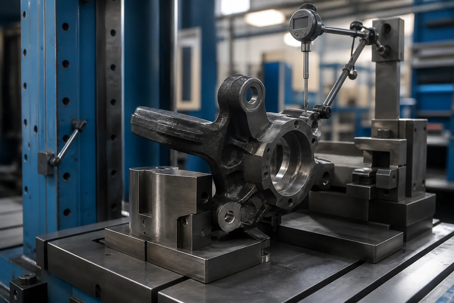
*Ilustración del concepto de ingeniería: un muñón de dirección sostenido en un dispositivo específico de la pieza con una sonda que monitorea la cara del cubo durante un estudio de corrección. No es una fotografía del sitio del cliente.. Posiciones de fuerza, Las opciones de datos y los límites de aceptación requieren el dibujo y las piezas de muestra representativas.*
Dos problemas diferentes se esconden detrás de una palabra clave
Resultados de DataForSEO para steering knuckle straightening Están dominados por foros de entusiastas y reparación de colisiones.: Hilos de Reddit que preguntan si un automóvil "conduce en línea recta" después de trabajar con los nudillos, Bob Is The Oil Guy debate sobre cómo flexionar un nudillo doblado, y solicitudes de reparación de grupos de Facebook. La única página técnica importante es un artículo de FenderBender sobre el diagnóstico de nudillos doblados a partir de datos de alineación utilizando SAI., gráficos de inclinación y ángulo incluido, y su conclusión para los talleres de colisión es contundente: Los nudillos escayolados “no se pueden reparar y deben reemplazarse si están dañados”.
Esa doctrina es correcta para su contexto (una pieza de seguridad cargada de choques con daños internos desconocidos) e irrelevante para otro contexto.: el entorno de producción y remanufactura donde la distorsión es una medida, artefacto de proceso repetible. Estos dos mundos no deben mezclarse en una sola oferta de solución.:
| Situación de los nudillos | De dónde viene la distorsión | Puesto de ingeniería |
|---|---|---|
| Articulación dañada por colisión en un vehículo reparado | Sobrecarga de impacto, historial de crack desconocido | Reemplazo, no enderezarse: la pieza es un componente de seguridad documentado |
| Mangueta de hierro dúctil o forjada en producción, antes o entre operaciones de mecanizado | Alivio del estrés por fundición o forja, tensión residual de mecanizado, tratamiento térmico | Corrección de distorsión medible bajo una ventana de proceso validada |
| Nudillo de aluminio fundido (tipo de puntal) después del mecanizado o envejecimiento por calor | Alivio del estrés del envejecimiento, apagar la distorsión | Corrección en frío limitada; evaluación de riesgos por aleación y temple |
| Núcleo de nudillos remanufacturado. | Desgaste de servicio, accidente previo, calor por falla del rodamiento | Puerta de inspección completa: grietas, Dureza y dimensión antes de cualquier corrección. |
Esta página aborda la segunda fila y sus vecinas.: control medido de la distorsión de los nudillos dentro de un proceso de fabricación o remanufactura. Nada aquí convierte un nudillo doblado en una pieza aprobada por seguridad. Para componentes de chasis adyacentes que se corrigen rutinariamente en producción, ver nuestro descripción general del enderezamiento de sistemas de chasis y la discusión de 3D enderezamiento de piezas estructurales giga-cast.
Definir la cadena de referencia antes que nada
Cada característica funcional del nudillo debe enumerarse y vincularse a un marco de referencia en el dibujo.:
- Orificio del cojinete del cubo: referencia del eje primario A;
- cara del cubo - referencia plana secundaria B, controlar el descentramiento del rotor de freno;
- Geometría del brazo de dirección: posición y altura del saliente del tirante., controlar los ángulos de articulación y la convergencia;
- orificios del pivote central (nudillos de eje sólido) o horquilla de puntal, ranura para perno de presión y cara de montaje superior (nudillos MacPherson);
- abertura inferior de la rótula o orificio de ajuste a presión;
- Resaltes y caras de apoyo del soporte de la pinza de freno;
- Detalles del orificio y brida del sensor ABS;
- Datos de proceso: localización de almohadillas y puntos de sujeción utilizados en el mecanizado..
El orificio del cubo normalmente ancla el marco porque la rueda y el rotor giran sobre él.. La lógica de diagnóstico del FenderBender: inferir un nudillo doblado a partir de la inclinación del eje de dirección, Camber y desviaciones de ángulo incluido: es la sombra del vehículo ensamblado de la misma geometría.: un muñón cuyo eje del orificio del cubo se ha inclinado en relación con las interfaces del puntal o de la rótula se muestra como un error de ángulo incluido que ningún ajuste de alineación puede absorber. En producción, la misma desviación se mide directamente en la pieza en lugar de en el automóvil..
Reconocer los patrones de deformación por separado
Tratar el “nudillo doblado” como una condición produce correcciones incorrectas. En la práctica dominan cuatro patrones, cada uno con una consecuencia funcional diferente y una ruta de corrección diferente:
| Patrón | Firma | Consecuencia funcional |
|---|---|---|
| Inclinación de la cara del cubo en relación con el eje del orificio | Desviación de la cara en la cara del cubo con el orificio pilotado | Desviación del rotor de freno, variación de espesor, vibración del freno |
| Desviación angular del orificio del cubo hacia las interfaces de suspensión | EFS / error de tipo de ángulo incluido medido entre características de referencia | Camber que no se puede alinear; desgaste de neumáticos |
| El brazo de dirección se dobla o gira | Resalte del tirante desplazado o girado con respecto a la raíz del brazo | Errores de Toe y Ackerman; fatiga del brazo bajo carga |
| Distorsión del orificio o desalineación del jefe | Error de redondez o posición en las características de ajuste a presión | Problemas con el ajuste de los rodamientos y el atornillado de la pinza; pertenece al tamaño, no doblarse |
Los dos primeros son verdaderos problemas de enderezamiento de la geometría de la carrocería.. La tercera es una corrección local del brazo con su propio plan de soporte y carga.. El cuarto debe dirigirse a una operación de dimensionamiento o calibración: presionar un orificio mientras se “endereza” corre el riesgo de enmascarar un problema de ajuste que volverá después del ensamblaje.. La misma lógica de separación se aplica a los componentes relacionados de la línea de dirección, como el proceso de enderezamiento automático de la cremallera de dirección y corrección de bola larga.
Estrategia de medición: Comparativo, Entonces absoluto
Los diagnósticos de colisión se miden comparativamente con la pieza del lado opuesto o una tabla de alineación porque no existen datos de dibujo en el taller.. La medición de la producción no debería heredar ese compromiso. La secuencia correcta es:
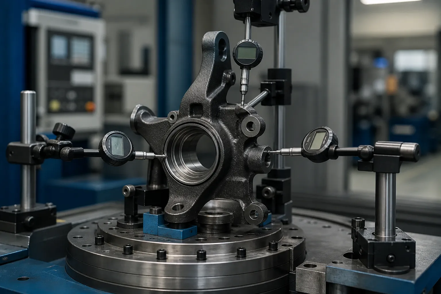
- Pilotar la pieza en el orificio del cubo. (o el orificio de referencia del mecanizado) en un dispositivo de rotación.
- Sondee la cara del cubo para determinar el descentramiento de la cara y la almohadilla del brazo de dirección y el saliente de la barra de dirección para determinar su posición y altura..
- Capture las características de referencia del pivote central o del puntal: orificios en un mandril, o la horquilla amortiguadora en superficies de contacto simuladas.
- Comparar con valores de muestra dorada o masterizados por CMM, no contra la parte opuesta.
- Registre la magnitud y dirección de la desviación para cada característica antes de intentar cualquier corrección..
Para trabajos remanufacturados de bajo volumen, una placa de granito con medidor de altura y un informe de CMM por familia puede ser suficiente. Para volúmenes de producción, el dispositivo se convierte en una estación en una máquina indexadora rotativa: sondas electrónicas multipunto, un cabezal de servoprensa, y un controlador que almacena el mapa de desviación de cada pieza antes de decidir la corrección. Un mapa de precorrección no es burocracia; sin él no hay forma de distinguir una distorsión global del cuerpo de un error local del brazo., y se carga la característica incorrecta.
Rutas de corrección y sus límites

Nudillos de hierro dúctil y acero forjado
Estos materiales toleran el prensado controlado en punto frío cuando se valida la ventana de corrección.. El plan de carga importa más que la capacidad de la prensa: soportes bajo la estructura rígida del jefe, carga aplicada en o cerca de la característica que se está corrigiendo, Carreras cortas con recuperación elástica medidas después de cada carrera.. Las correcciones son iterativas: presione, liberar, volver a medir, porque las piezas fundidas liberan la tensión de manera desigual, y una corrección en el brazo puede cambiar la lectura de la cara del cubo. Repita el mapa de sonda completo después de cada ciclo., no solo la característica que se cargó.
Nudillos de aluminio fundido
Los nudillos de aluminio fundido a presión con temples tipo T6/T7 tienen baja ductilidad y una reputación bien ganada de agrietarse bajo flexión en frío incontrolada.. Correcciones, donde esté aprobado en absoluto, son de ángulo pequeño, baja velocidad, y validado por aleación y temple en muestras de sacrificio, seguido frecuentemente de un tratamiento de estabilización. Muchos programas de nudillos de aluminio simplemente establecen un control más estricto del proceso aguas arriba y la distorsión de la chatarra; esa decisión pertenece al metalúrgico., no al vendedor de la máquina.
¿Qué punto no se puede arreglar al presionar?
Los brazos de dirección que sufrieron una sobrecarga de flexión son una cuestión de fatiga y responsabilidad, no es una pregunta de geometría. La corrección de brazos cargados por impactos en piezas de seguridad terminadas debería estar descartada incluso cuando la geometría se lee inmediatamente después: la misma doctrina de reemplazo que aplica la industria de colisiones.. El enderezamiento gana su lugar en la distorsión inducida por el proceso donde se conoce el historial de carga y se valida la ventana de corrección..
Puertas de aceptación

Un proceso de enderezamiento liberado para los nudillos debe contener cuatro puertas., en orden:
- Pre-puerta: detección de grietas (partícula magnética o equivalente para piezas ferrosas) antes de la corrección: enderezar una grieta existente destruye la evidencia y la pieza..
- Puerta de geometría: mapa completo de características de referencia dentro de los límites del dibujo: descentramiento de la cara del cubo, ángulos entre el orificio y la suspensión, Posición del brazo: medida después de la corrección y después de cualquier paso de estabilización o alivio del estrés..
- Puerta de estabilidad: Nueva medición después de la siguiente operación de mecanizado o calentamiento.; una corrección que relaja la espalda fue la superposición de estrés, no corrección.
- Puerta de trazabilidad: mapa de desviación de cada parte, recuento de corrección y lecturas finales almacenadas contra su número de serie, con un límite de retrabajo definido más allá del cual la pieza se desecha en lugar de prensarse nuevamente.
Definir honestamente ese límite de retrabajo (y las reglas de clasificación NOK que lo rodean) es lo que separa una línea de enderezamiento de una prensa en una esquina.. Nuestra visión general de Límites de clasificación y retrabajo NOK en una línea de enderezamiento cubre la estructura de decisión.
Errores comunes
- Orden de referencia incorrecto. La corrección de la cara del cubo mientras el orificio es el eje funcional produce una pieza que pasa una verificación y no pasa el ensamblaje..
- Remedición de una característica. Verificar solo la característica corregida oculta cambios cruzados en otras partes del cuerpo.
- Piezas fundidas sobreprensadas. Perseguir la última fracción de milímetro con trazos pesados cambia la geometría visible por microfisuras invisibles.
- Saltar la nueva verificación de estabilidad. La distorsión que regresa después de la siguiente operación de mecanizado es la firma clásica de tensión residual no aliviada., y le aparece al cliente, no en tu celda.
- Sin puerta de grieta antes de la corrección. Una grieta preexistente se convierte en una falla de campo con su trazo de corrección como causa documentada..
Congele la etapa del proceso antes de corregir
Cuándo se produce la corrección en la ruta es tan decisivo como cómo se hace. Un nudillo medido inmediatamente después de la fundición o forja conlleva variación de material y tensiones residuales que se relajarán parcialmente durante el mecanizado.; corregir a la geometría final en esa etapa significa corregir un cuerpo que está a punto de cambiar. Las prácticas ventanas son:
- Después del mecanizado en desbaste, antes del semiacabado: Existen características de referencia funcionales y el stock permanece (generalmente la mejor ventana)., porque la corrección apoya el pulido y el aburrimiento en lugar de luchar contra ellos.
- Después del tratamiento térmico o del endurecimiento por inducción del orificio del cubo.: La distorsión está en su punto máximo y una corrección validada recupera piezas que de otro modo serían desechadas., pero el estado material limita la ventana.
- Después de terminar el mecanizado: la corrección se limita a pequeñas desviaciones angulares; Todos los riesgos de la puerta de estabilidad se aplican y la recompensa debe justificarlo..
El escenario también decide qué significa “heterosexual”. antes de terminar de aburrir, el agujero del cubo aún no es definitivo y el dato debe provenir de los datos de mecanizado; después de terminar aburrido, el agujero mismo se convierte en la referencia honesta. Una especificación de enderezamiento que no nombra su punto de proceso es una especificación que dos departamentos interpretarán de manera diferente, que es la forma en que las piezas se corrigen correctamente en la etapa incorrecta y aún así fallan en el ensamblaje..
Lo que contiene una consulta seria
Para cotizar una estación de alisado de nudillos de forma responsable, un proveedor necesita: el dibujo con el esquema de referencia y la hoja de tolerancias; Estado del material y del tratamiento térmico en el punto de corrección.; dónde se mide hoy la distorsión y con qué resultado la distribución; piezas de muestra que cubren bien, condiciones límite y NOK; el tiempo de ciclo requerido; y las reglas de retrabajo y desecho que aceptará la planta.. Con esos aportes el concepto de luminaria, El plan de sonda y la arquitectura de la prensa se siguen directamente, sin ellos., cualquier propuesta de máquina es una suposición sobre qué característica realmente define "directo" de su parte.
Todavía sopesando opciones para enderezar los nudillos de dirección.? El guía de selección de máquinas para ejes, tubos y perfiles y el desglose de precios para máquinas enderezadoras están escritos exactamente para esta etapa de la decisión.