
Core pins form the internal features of injection-molded and die-cast parts — holes, jefes, bores and recesses that molten resin or aluminum flows around at full injection pressure. Unlike an ejector pin, which only pushes a finished part out of the cavity, a core pin is a form-defining element: its geometry is literally the product’s geometry. Straightness errors on a core pin appear directly as tapered holes, wall-thickness variation, bind on ejection, and pin breakage at the worst moment — mid-production, when the mold is hot and cycling fast.
A core pin straightening solution has to answer five questions before machine selection:
- Is this a production pin between grinding operations, or a broken/bent pin recovered from a production mold?
- Which features define the datum — the mounting base, the ground forming section, or the free end?
- Is the deviation a global bow, a local bend, an out-of-round forming diameter, or base-to-form coaxiality error?
- Which correction route fits the material and slenderness — micro point-press, hand-leveling with inspection, or replacement for very small pins?
- How will released straightness, surface finish and (for small pins) freedom from handling damage be verified?

*Representative workshop photograph. Actual pin dimensions, materials and correction limits follow the component drawing and a validated process study.*
What the Search Results Show — and Why This Page Exists
Resultados de DataForSEO para core pin straightening return almost nothing about industrial core pins: the page is dominated by consumer advice on straightening bent CPU socket pins with mechanical pencils. The industrial reality is that core pin suppliers grind these pins to tight straightness on CNC cylindrical grinders, and molders keep spare pins because a bent pin is often treated as a consumable. But custom core pins in H13, M2, SKD61 or tungsten carbide — with long lead sections, stepped profiles, oblong or square sections — are expensive and slow to replace, which is exactly where a controlled straightening process pays for itself.
| Core Pin Family | Contexto típico | Ruta de la ingeniería |
|---|---|---|
| Stepped cylindrical core pin (H13 / SKD61, nitrurado) | Injection mold holes and bosses | Inter-operational straightening with protected nitrided surfaces |
| Long slender pin, small diameter-to-length ratio | Deep holes in tubular or medical parts | Micro point-press or selective roll correction; breakage risk governs |
| Die-cast core pin (H13, high thermal cycling) | Aluminum/zinc die casting | Heat-check inspection before any correction decision |
| Carbide core pin | High-wear or glass-filled applications | Restricted: carbide is stiff but brittle; only validated micro-correction or replacement |
| Bent pin pulled from a production mold | Mold maintenance | Damage and crack inspection first; disposition before force |
Know the Anatomy and the Datum Chain
A core pin typically combines a mounting base (cylindrical or with flat, threaded or key features), a head/shoulder that seats against the mold plate, and one or more ground forming sections — sometimes with a taper, vent flat or oblong profile. The functional requirement is that the forming section stands true relative to its mounting datum, so the pin does not lean inside the cavity under injection pressure.
The measurement plan should therefore record:
- the drawing datum system and how the pin is held in the mold (press fit, sujetado, threaded);
- straightness of the forming section as a centerline deviation — not a single dial reading;
- roundness and diameter of each forming section (out-of-round reads as runout but is a form problem);
- base-to-form coaxiality, which controls how the pin stands once installed;
- shoulder squareness and flat features orientation;
- condición de la superficie: polishing quality, nitride layer, heat checking on die-cast pins, adhesive wear from resin.
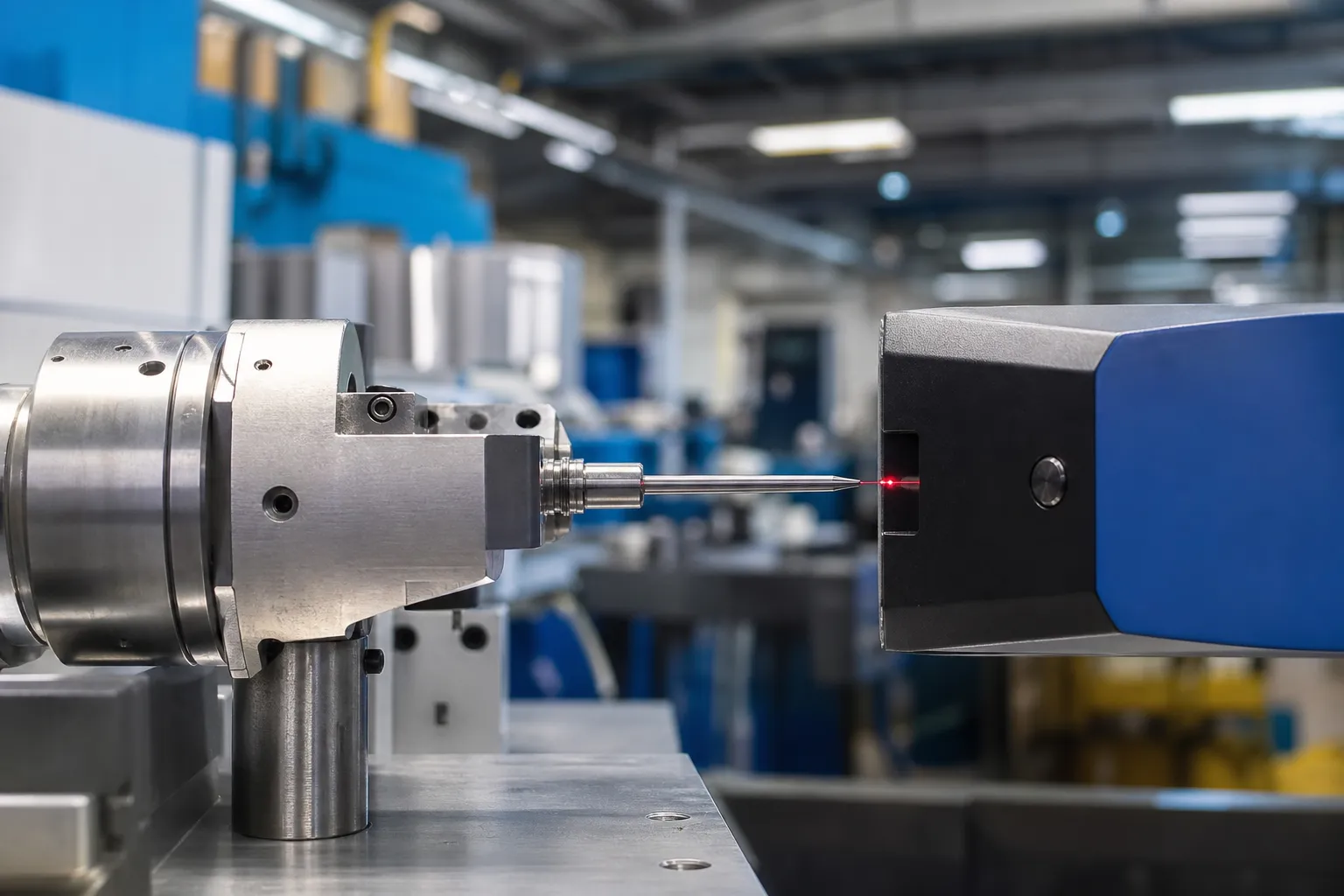
*Non-contact measurement is preferred on thin finished pins to avoid probe-force deflection; the sensor-layout logic is the same as in LVDT multipoint shaft measurement, scaled down.*
Congelar la etapa del proceso
Después del mecanizado de desbaste, Antes del tratamiento térmico
Correction is trivial in the soft state but low-value: heat treatment will re-introduce distortion. Straightening here is justified only to keep grind stock uniform on long pins.
After Hardening and Tempering — the Main Case
H13/SKD61 pins hardened to the mid-40s HRC and M2 pins in the low-60s HRC bow measurably during quenching. Straightening at this stage is the highest-value window: the ground surface does not yet exist, contact happens on grind stock, and the finishing pass still controls final form and finish. Expect strong springback — recipes from soft blanks do not transfer, as discussed in alisado después del tratamiento térmico.
After Nitriding or Coating
Nitrided layers and PVD coatings are thin and functionally tied to surface integrity. Any post-coating correction is a restricted operation: limited bend allowance, protected contact, and verification that the layer is not cracked or flaked. If a nitrided pin is far out, regrind within case depth or replace.
After Finish Grinding or From a Used Mold
The pin is now a finished precision surface. Correction is confined to gentle micro-pressing with soft or non-marring tooling on approved zones, and only for residual errors the grinder could not remove. Pins recovered after a mold crash need a crack and heat-check inspection first — bent core pins from die casting frequently carry thermal fatigue cracks that correction would propagate.
Classify the Deviation Before Applying Force
| Desviación | Evidencia | Ruta correcta |
|---|---|---|
| Global bow (tratamiento térmico) | Smooth single-arc map along the forming section | Point-press at the apex, incremental, released recheck |
| Local bend near the free end | Sharp runout change over a short length | Close-support local correction; check for cracks; verify the tip geometry after |
| Out-of-round or tapered section | Runout varies with angular position, not length | Regrind — straightening cannot restore form |
| Base-to-form coaxiality error | Form section straight but offset at the base | Regrind datum features; do not bend the form section to chase the base |
| Heat checking / wear on die-cast pin | Fine surface cracks, scaling, material transfer | Disposition by inspection standard — usually rework or replace |
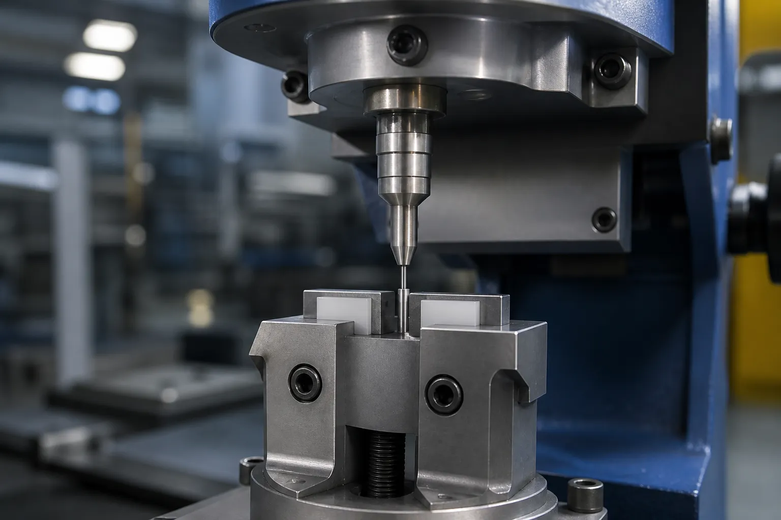
Correction Method and Protected Contact Map
Because core pins are slender, the process is a scaled-down version of alisado con prensa puntual: rotate the pin between centers or in V-supports, map the bend, index the apex to a micro-press, and apply small incremental loads. On very thin pins the boundary between straightening and buckling is narrow, so force ceilings must be established on samples and the process stopped on any abnormal stiffness change. Springback behavior on hardened slender pins follows the compensation logic in Compensación del retorno elástico del enderezamiento del eje.
Default no-press and no-clamp zones:
- finished and polished forming surfaces without protected tooling approval;
- shoulder fillets and small section transitions (breakage initiation sites);
- vent flats, oblong edges and small tip features;
- nitrurado, coated or textured zones;
- trapos, keys and clamp flats on the mounting end.
Handling is part of the process: a correctly straightened pin that is afterwards dropped or gripped with pliers is scrap. Soft-lined supports, dedicated trays and non-marring collets are not accessories — they are acceptance conditions, in line with surface-protection tooling in straightening.
Closed-Loop Process
- Identify the pin: part number, acero, dureza, revestimiento, escenario, rework history.
- Clean and inspect: acabado superficial, grietas, heat checking, tener puesto.
- Qualify the setup: centers/V-supports suited to the pin’s slenderness, low sensor force.
- Map straightness along every forming section, full rotation.
- Classify the deviation; route form errors and damage out of the press.
- Index the apex, apply incremental micro-loads within validated ceilings.
- Liberar completamente, remeasure the complete map; iterate within the allowed count.
- Verify released straightness, coaxiality, surface condition and tip features.
- Record maps, force curves and disposition for traceability.
Acceptance Criteria
- forming-section straightness within the drawing specification, measured released, full rotation, no probe-force artifacts;
- base-to-form coaxiality within the mold assembly tolerance;
- surface finish and coating condition unchanged (no marks, no flaking);
- diameters and roundness untouched by correction;
- no crack or heat-check indications where NDT is specified;
- a protected fit-and-slide check in the mold plate and ejector system before release to production.
Common Pitfalls in Core Pin Straightening
- Over-pressing thin pins. The gap between correcting a slender pin and buckling or snapping it is small; incremental loads with force ceilings from sample trials are the only safe approach.
- Correcting to chase a base error. If the form section is straight but the mounting base is offset, bending the form section to compensate hides the defect until the mold heats up — then the pin leans and binds. Fix the datum, not the symptom.
- Pressing on shoulders and fillets. Section transitions on small pins are the classic fracture origins; contact belongs on the plain ground body within its stock envelope.
- Correcting after nitriding or coating without a plan. Bending strains the thin hardened layer; the layer cracks at the compressed side, and the crack becomes a fatigue initiator in production.
- Handling damage after good correction. Thin straightened pins laid loose in a tray or gripped with hard tools pick up marks and new bends. Soft trays and non-marring collets are acceptance conditions.
- No correction-count control. Each additional press cycle cold-works the bend zone. A pin that needs the fifth correction is telling you it wants a different disposition.
Datos requeridos para una propuesta técnica
- pin drawing and revision, with datum system and fit specifications;
- grado de acero, dureza, and nitride/coating specification with layer depth;
- etapa del proceso: post-heat-treatment, nitrurado, suelo, or recovered from a mold;
- forming section diameters, lengths and slenderness; special sections (oblong, cuadrado, afilar);
- tip and vent features;
- incoming straightness maps by section and angle;
- base-to-form concentricity requirement from the mold design;
- zonas de contacto aprobadas y prohibidas;
- remaining grind stock;
- straightness acceptance value and measurement method (contact or non-contact);
- lot sizes and handling/automation expectations;
- inspection requirements (superficie, END) and traceability needs;
- representative samples for correction trials.
Preguntas frecuentes
What is the difference between a core pin and an ejector pin for straightening?
An ejector pin is a pusher: its critical features are the running diameter in the plate and the flat ejecting face, and the process is described in the ejector pin straightening solution. A core pin is a form element: its entire ground body defines product geometry, so contact restrictions are tighter, slenderness is higher, and acceptance includes the shape of the formed feature, not just a running fit.
Can a bent core pin be straightened, or should it be replaced?
Heat-treatment bows and gentle handling bends on steel pins are routinely correctable. Agrietado, heat-checked, coated with damaged layers, or carbide pins usually route to replacement. The decision is made per deviation class, material and stage — not by a blanket rule.
Why do straightened core pins still break in production?
Common causes are not straightness at all: coaxiality error so the pin leans under injection pressure, an out-of-round section causing bind on ejection, fatigue cracks introduced before correction, or repeated correction cycles work-hardening the bend zone. This is why the process records correction counts and inspects before and after.
How straight must a core pin be?
The functional limit comes from the formed-feature tolerance and the pin’s slenderness — deep-hole pins for medical or tubular parts need the tightest control. The number must come from the product drawing and mold design, established the same way as in medical mandrel straightening, not from a generic table.
Build the Solution Around the Forming Geometry
Core pin straightening succeeds or fails on one question: what straightness does the cavity fit actually need in the released part? The mold’s fit requirements convert “as straight as possible” into a number, and that number – not general pin practice – sets the correction envelope. Related processes are collected in the mold and die straightening hub.
Send the pin drawing with the cavity fit tolerance called out, material and hardness specification, etapa del proceso, incoming straightness maps and representative samples. The measurement strategy, sobre de corrección, tooling map and acceptance plan follow from that fit tolerance.