
Buy a straightening machine and you have a machine. Plan a straightening step and you have a line. The difference is everything that happens around the press: how parts arrive, how long they wait, where rejects go, how the process proves itself, and what the step costs the plant per good part. Most general lean material on line balancing assumes stations with fixed cycle times; a straightener’s cycle is a loop that repeats until each part passes, which makes the layout and buffering decisions different from a classic assembly line.
This article is about the production-engineering layer: layout patterns, cycle-time analysis, buffering, تبدیلی, and acceptance for a straightening operation. It is the line-level companion to two more focused pages: خودکار شافٹ سیدھا کیسے کام کرتا ہے۔ for the machine cycle itself, and our comparison of manual vs automatic straightening for the decision on how much automation the step needs.
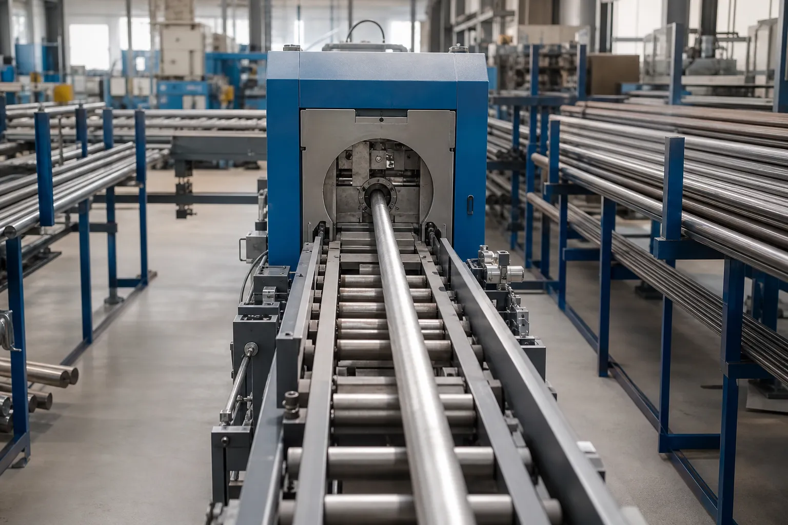
The Cycle Time of a Straightening Station Is a Distribution
A straightening station’s cycle decomposes into: part load and seating, initial measurement, one or more press-and-remeasure iterations, final measurement and record, and unload with disposition. Only the load and unload portions are fixed. The correction loop runs until the part is inside tolerance or hits the press-count limit, so two identical-looking parts can consume very different station time – a light single-plane bend exits after one press, a multi-plane bend takes several iterations.
Planning consequence number one: never size the line on the average cycle. Size it on a high percentile of the measured distribution – the slowest parts that still occur in normal production – or provide the means to absorb them. Planning consequence number two: the incoming bend distribution is a process input you can influence. Parts arriving from a stable heat-treatment source have a predictable bend distribution; parts from an unstable one do not, and the straightening station pays for that instability in rate. Tracking the incoming distribution – initial measurement values are recorded per part anyway – tells you whether the upstream process is drifting long before the straightener starts missing takt.
Where the Station Sits in the Flow
Straightening stations almost always live between two other operations, and the neighbors shape the layout:
- گرمی کے علاج کے بعد, پیسنے سے پہلے. The classic position: correct the distortion the furnace added, with grinding stock left to clean up tooling effects and hold final diameter. The buffer in front of the straightener has to absorb heat-treatment batch releases, which do not arrive takt-neutrally.
- After deep-hole drilling or rough machining. For parts whose bore or machining stresses dominate, an earlier correction gate keeps later operations working on straight stock.
- Before assembly-critical inspection. Some lines place straightening directly in front of final measurement, which makes measurement capacity and correction capacity a coupled pair.
The neighbors also define the failure modes. If the upstream operation stops, the straightening station starves; if the downstream grinders stop, good parts stack up in front of them. Buffer sizing between the straightener and its neighbors is therefore not a detail – it is the mechanism that lets a variable-cycle station coexist with fixed-cycle neighbors.
Auxiliary operations are neighbors too, and they are easy to forget until they constrain the line. Washing before measurement keeps sensing surfaces and centers reliable on oily parts. Crack detection – whether eddy current integrated in the machine or a separate NDT station – has its own capacity and its own qualification requirements, and parts that fail there need a routing that does not cross the good-part flow. Marking and identification, if parts must carry a traceable mark after correction, is another station with a rate. Each of these deserves a place in the layout study with an honest capacity number, not a line item to be added later wherever there is floor left.

Layout Patterns and Where Each Fits
- Straight inline. Conveyor in, مشین, conveyor out. Simplest material flow and the easiest to understand at a glance; works when one machine meets takt and part variety is low. The NOK lane branches off the outfeed.
- Cell with automation. Machine plus robot or gantry, with infeed buffer, outfeed lanes for good/rework/NOK, and sometimes a marking or measurement station inside the cell. The pattern for higher rates and unattended shifts; the automation decisions are covered in the robot tending article.
- Parallel machines sharing handling. When one machine cannot meet takt but the parts are identical, two machines with a shared loader split the flow. This also buys redundancy: one machine down halves rate instead of stopping the line.
- Manual U-shaped cell. For high-mix, کم حجم کا کام, a semiautomatic machine inside a U-cell with incoming and outgoing racks at arm’s reach minimizes walking and keeps one operator productive across several part numbers.
Two layout elements are chronically under-designed. The NOK lane needs real capacity – sized against the worst realistic reject rate, with a full-lane reaction defined – because rejects arrive in clusters when upstream drifts. And staging between operations needs part protection: long slender shafts resting on inappropriate supports accumulate the very distortion the line exists to remove. The disposition rules behind the lanes are covered in سیدھی لائن میں NOK چھانٹنے اور دوبارہ کام کرنے کی حدود.
Buffers: The Coupling Between Variable and Fixed Cycles
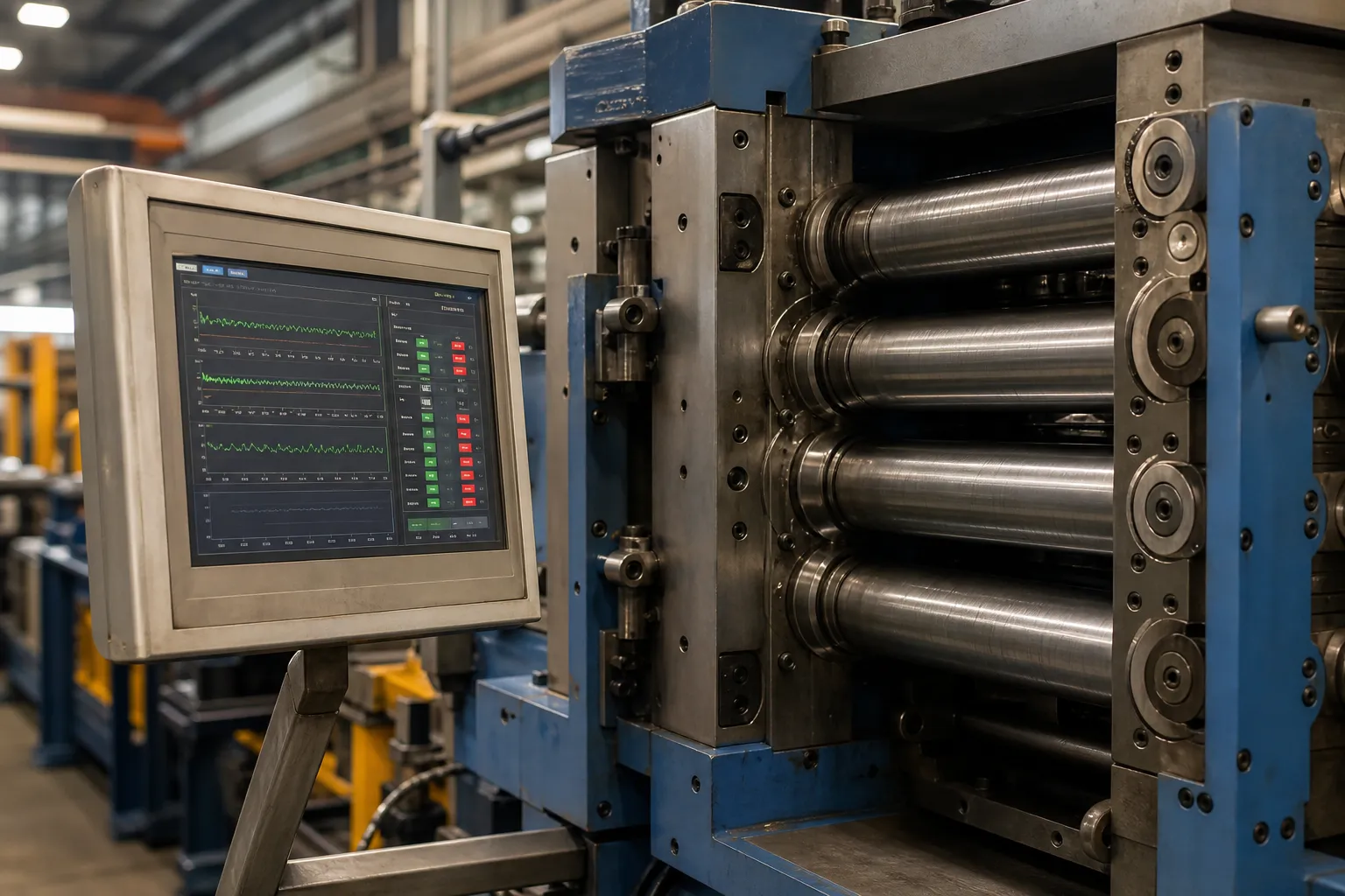
A buffer converts timing mismatch into inventory. Between a batch heat-treatment source and the straightener, the buffer absorbs batch releases; between the straightener and fixed-cycle grinders, it absorbs the correction-loop tail. The design questions are capacity, part protection, and information: a first-in-first-out buffer preserves process order for traceability, and a buffer with per-part status preserves the measurement record that travels with each piece. What a buffer must never do is hide a problem – a buffer sized to absorb a permanently drifting upstream process does not fix the drift, it delays the discovery.
A practical review sequence for an underperforming straightening line: measure the station’s cycle distribution, check what the buffer levels do across a shift, and compare the machine’s per-part records against shift output. The combination almost always locates the constraint in one of three places – the upstream source, the correction loop itself, or the handling around it – and each has a different remedy.
تبدیلی, شرح, and OEE
On high-mix lines, changeover dominates the economics. The changeover elements are: support and tooling setup for the new part, measurement recipe selection, press parameters, and handling adjustments. Machines with stored part recipes and quick-change support tooling compress this to minutes; machines without it make every part change a small project. Over a week, changeover time, the correction-loop tail, NOK handling and planned maintenance together determine the output that matters – good parts per shift, not theoretical cycles per hour. That is the number to track, per part number, with the per-part measurement data the machine already produces; a straightening line that is instrumented per part is effectively its own SPC system, provided the measurement variation is understood and bounded – which is the role of the analysis described in گیج آر&لائنوں کو سیدھا کرنے کے لیے R.
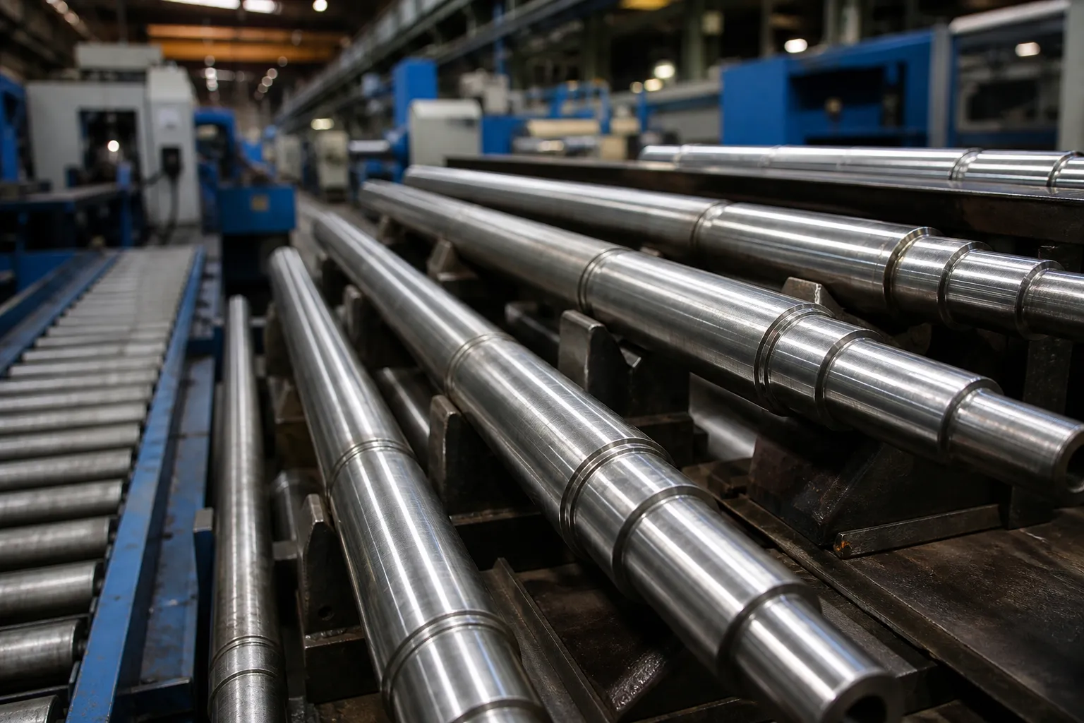
A useful discipline is to run changeover as a measured operation from day one: time it, film it, and attack the longest element first. On most high-mix straightening lines the longest element is not the physical tooling swap but the verification that follows it – proving that the new setup measures and corrects the new part correctly. Stored recipes help only if they carry the verified parameters; a recipe that still needs an engineer to prove it by trial has not really saved the changeover.
قبولیت: Proving the Line, Not the Machine
A line acceptance for straightening should test the system as it will run: representative production parts at realistic mix, throughput measured over a sustained window against the agreed percentile cycle, NOK handling exercised with forced rejects, and records reconciled – parts in equals good parts plus documented NOKs. The machine-level acceptance elements come from the same source as the line-level ones: the checks in the straightening machine FAT checklist, extended with part-family evidence of the kind discussed in سیدھا نمونہ ٹیسٹ اور قبولیت. Running acceptance with the real part mix, not a single demonstration part, is what separates a signed-off line from a commissioned machine that surprises everyone in week two.
A note on the images in this article: they are engineering concept illustrations created for this article, not photographs of a specific customer line, machine model, or installation, and they are intended to support the process discussion only.
اکثر پوچھے گئے سوالات
How much floor space does a straightening cell need?
Beyond the machine footprint, plan for: infeed and outfeed conveyors or racks sized to the buffer strategy, the NOK lane, access for maintenance on all sides of the machine, and space for a pallet or bin of the largest part family. Automation adds the robot envelope and its safeguarding. The dominant sizing variable is almost always buffer and lane capacity, not the machine itself.
Should the buffer be before or after the straightener?
Usually both, doing different jobs. The inbound buffer absorbs upstream batch behavior; the outbound buffer decouples the correction-loop tail from fixed-cycle downstream stations. Capacity belongs where the variability is: batch-releasing heat treatment drives inbound capacity; variable press iterations drive outbound decoupling or a shared-loader second machine.
How do we justify a second straightening machine?
The clean cases are: measured demand exceeding the percentile cycle of one machine, redundancy requirements for line-critical parts, or a genuinely different part family that would otherwise force constant changeover. The first case is arithmetic on the cycle distribution; the second is a risk decision; the third is a changeover-time analysis. All three are answerable from the per-part records the machine already produces.
What data should a straightening line produce per part?
The minimum useful record is: part identifier, initial bend measurement, number and parameters of press iterations, حتمی پیمائش, and disposition. Downstream, that record feeds acceptance evidence, upstream process monitoring, and yield accounting; upstream, the initial-measurement distribution is an early-warning channel on heat treatment or machining drift. Lines that treat this data as an output of the process rather than an optional accessory get their layout decisions answered with evidence instead of opinion.
نتیجہ
A straightening step earns its place in a plant when the line around it is engineered for what the process actually is: a variable-cycle correction loop with real reject flow, sitting between neighbors with their own rhythms. Size against the cycle distribution, buffer the real variability, give NOK parts a designed lane, keep changeover measured and small, and accept the line as a system with production parts. Teams that do this treat the straightening station as what it has become in modern production – a data-producing quality gate, not a repair bench. If you are laying out a new straightening operation or reworking one that misses rate, bring the part spectrum, the upstream process, and the takt requirement to the discussion early.