
Vodiace skrutky premieňajú rotačný pohyb na riadený lineárny pohyb v pohonoch, polohovacie systémy, kompaktné zostavy automatizácie a krokových motorov. Malý ohyb môže vytvoriť radiálne hádzanie, nerovnomerný pohyb matice, hluk, pridané zaťaženie ložiska alebo ťažkosti s montážou. Pretože závit je funkčný povrch aj ťažká kontaktná geometria, vodiacu skrutku nemožno považovať za obyčajnú okrúhlu tyč.
Toto navrhované riešenie vyrovnávania vodiacej skrutky kombinuje opakovateľnú základnú podporu, rotačné meranie, lisovanie chráneného bodu a kompletné premeranie. Je založená na informáciách o zákazníkoch pre dve veľmi odlišné rodiny kandidátov: krátky Ø6,35 × 75 mm skrutka a štyri kusy vzorky označené ako Ø3,5 × 508 mm. Tieto rozmery vytvárajú pomer dĺžky k priemeru približne 11.8 a 145.1, takže vyžadujú samostatné okná uskutočniteľnosti, a nie jeden predpokladaný strojový recept.
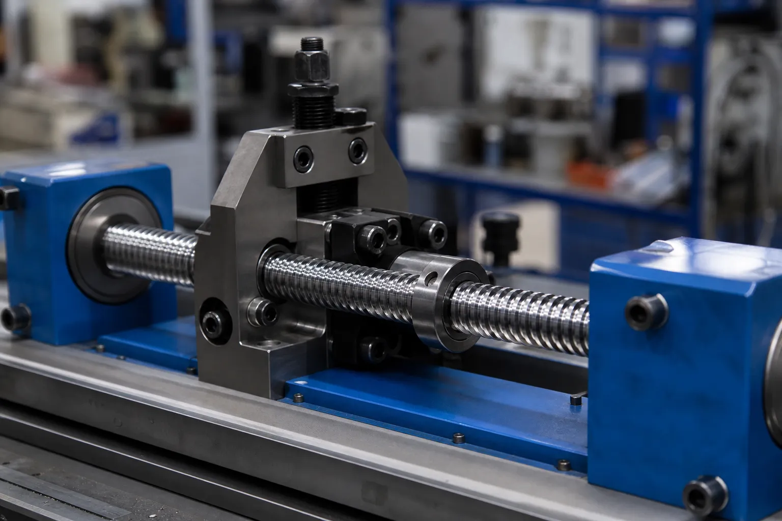
*Rám zdrojového videa.* Zobrazuje skrutku so závitom v kompaktnej stanici, ale neurčuje žiadnu geometriu zákazníka, automatické nakladanie alebo výrobná kapacita.
Požiadavka projektu vodiacej skrutky
Zákazník popisuje aplikáciu ako vodiacu skrutku krokového motora a uvádza elektrický výkon motora 2.33 VDC at 1.5 A. Toto hodnotenie môže pomôcť identifikovať zostavu, ale nedefinuje tuhosť hriadeľa, vyrovnávacia sila, meraný údaj alebo prijateľné hádzanie. Návrh vyrovnania musí vychádzať z výkresu skrutky, materiál, tepelné spracovanie, závitový formulár, štádium procesu a toleranciou rozmerov.
Riadok uvádzajúci „štyri kusy, Ø3,5 × 508 mm“ sa považuje za množstvo vzorky pre druhú geometriu, kým zákazník nepotvrdí inak. Nemalo by sa automaticky spájať s Ø6,35 × 75 mm diel alebo sa používa na uplatnenie univerzálneho sortimentu strojov.
| Projektová položka | Zákaznícky vstup / Stav |
|---|---|
| Obrobok | Vodiaca skrutka spojená s aplikáciou krokového motora |
| Kandidátska rodina A | Ø6,35 mm × 75 mm; L/D ≈ 11.8 |
| Kandidátska rodina B | Štyri nahlásené vzorky, Ø3,5 mm × 508 mm; L/D ≈ 145.1 |
| Hodnotenie motora | 2.33 VDC at 1.5 A; iba označenie zostavy, nie je vstup na vyrovnávanie |
| Aktuálne vybavenie | Zákazník hlási predchádzajúce použitie zariadenia Galdabini |
| Materiál / Tvrdosť | Na potvrdenie |
| Formulár závitu / Olovo | Na potvrdenie |
| Prichádzajúci ohyb | Merať na reprezentatívnych vzorkách |
| Konečná požiadavka | Rovnosť alebo TIR, nulové a meracie polohy, ktoré sa majú potvrdiť |
| Navrhovaná metóda | Rotačné meranie v uzavretej slučke a vyrovnávanie lisovaním s chráneným bodom |
Prečo dvojveľké rodiny potrebujú samostatné okná uskutočniteľnosti
Priemer má silný vplyv na ohybovú tuhosť, zatiaľ čo dĺžka mení správanie podpory aj citlivosť merania. The 75 mm skrutka je dostatočne kompaktná, aby umožnila prístup k zariadeniu, krátke rozpätia podpory a umiestnenie prvkov môžu dominovať dizajnu. The 508 mm skrutka je extrémne štíhla vzhľadom na jej priemer, takže jeho zdanlivé čítanie sa môže meniť s rozstupom podpory, držanie tela, sila sondy a jej vlastná hmotnosť.
Tieto dve rodiny sa môžu stále zmestiť do jednej modulárnej strojovej platformy, ale tento záver si vyžaduje testovanie vzorky. Môžu potrebovať rôzne podpory, rozsahy sondy, geometria lisovacieho kontaktu, korekčné prírastky, metódy zaťaženia a dokonca aj rôzne orientácie merania.
| Inžiniersky faktor | Ø6,35 × 75 mm Rodina | Ø3,5 × 508 mm Rodina |
|---|---|---|
| Geometria | Krátky závitový hriadeľ | Ultra tenký závitový hriadeľ |
| Primárne riziko príslušenstva | Obmedzený priestor pre podpery, sonda a lisovací nástroj | Samovychýlenie a nestabilná podpora s dlhým rozpätím |
| Citlivosť merania | Umiestnenie prvku a chyba skľučovadla/podpory | Podporná poloha, sila sondy, držanie tela a narušenie prostredia |
| Stratégia korekcie | Krátke rozpätie, korekcia bodu jemného posunu | Viacpolohová podpora a veľmi malá stupňovitá korekcia po teste uskutočniteľnosti |
| Manipulácia | Je možné manuálne hniezdenie alebo kompaktné automatické podávanie | Pravdepodobne bude potrebné dlhé vedenie a manipulácia proti zamotaniu |
| Predpoklad zdieľaného receptu | Nie je povolené | Nie je povolené |
Priamosť, Rázový a funkčný dátum
Priamosť a radiálne hádzanie nie sú zameniteľné. Priamosť popisuje odchýlku prvku od ideálnej priamky. Radiálne hádzanie alebo celkové indikované hádzanie sa meria, keď sa dielec otáča okolo definovaných referencií, a preto závisí od zvoleného nulového bodu. Rozdiely sú podrobnejšie opísané v priamosť hriadeľa, runout a TIR.
Pre presnú skrutku, funkčná referencia často súvisí s ložiskovými čapmi, podpora končí, stredy alebo iný základ výkresu. THK popisuje meranie hádzania hriadeľa skrutky vzhľadom na os podpery, vrátane podpory na čapových častiach a odčítaní v niekoľkých axiálnych polohách pri otáčaní hriadeľa. KURODA tiež uvádza hádzanie ložiska a celkové hádzanie alebo zakrivenie celého stredu skrutky a hriadeľa medzi položkami kontroly guľôčkových skrutiek. Tieto princípy ukazujú, prečo sa cenová ponuka nemôže zakladať len na vonkajšom priemere a dĺžke.
| Položka prijatia | Pred zárukou sa vyžaduje definícia |
|---|---|
| Riadená charakteristika | Priamosť hriadeľa, radiálne hádzanie, TIR alebo montážny výbeh |
| Dátum | Ložiskové čapy, stredísk, konce podpery alebo odkaz definovaný výkresom |
| Meranie pozícií | Presné hladké priemery, obvod matice alebo vyhradené polohy meradla |
| Meranie držania tela | Horizontálne, vertikálny alebo výkresovo prispôsobený stav podpery |
| Metóda sondy | Kontaktná sila, geometria hrotu, rýchlosť otáčania a filtrovanie |
| Konečný limit | Metóda numerickej tolerancie a meracej korelácie |
| Prijatie povrchu | Povolené známky na časopisoch, závit a nefunkčné oblasti |
Prečo závitový povrch mení proces
Skrutkovitý závit nepredstavuje rovnaký signál ako hladký valcový čap. Sonda umiestnená priamo na hrebeni môže sledovať geometriu závitu, zmena povrchu alebo pohyb súvisiaci s výškou sklonu namiesto len stredovej čiary hriadeľa. Uprednostňuje sa meranie na hladkom ložiskovom čape alebo schválenom referenčnom priemere, ak predstavuje funkčný údaj.
Ak výkres neposkytuje vhodnú hladkú meraciu plochu, riešenie môže vyžadovať špeciálnu hlavnú maticu, meranie obvodu matice, optická metóda alebo iný overený koncept meradla. The method must be proven against the customer's final inspection; nemal by sa vyberať iba zo snímky videa.
Pri korekcii je rovnako dôležitá ochrana závitu. Roton odporúča lisovacie vyrovnávanie pre vodiace skrutky a varuje, že metódy vyrovnávania valcovaním určené pre hladké tyče môžu poškodiť závity. Jeho vedenie si vyžaduje kontrolovaný pohyb barana a mäkké topánky na barane a podperách. Konečný kontaktný materiál a profil musia byť stále zvolené pre skutočný materiál skrutky, tvrdosť, dokončiť a povolené kontaktné zóny.
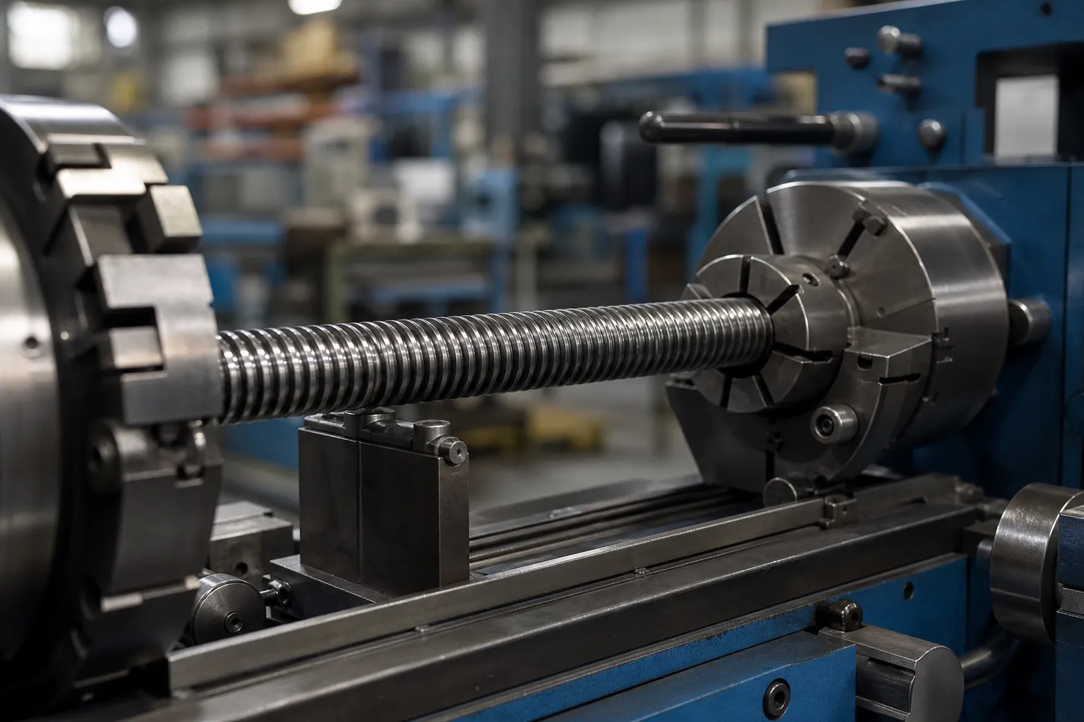
*Snímka zdrojového videa.* Výber dátumu, kontaktné miesta a relevantnosť merania musia byť potvrdené zo schváleného výkresu.
Odporúčaná metóda vyrovnávania
Preferovaným východiskovým konceptom je automatické bodové vyrovnávanie lisovaním s meraním rotačného hádzania. Diel je podopretý na dohodnutom základe, otočený, aby sa lokalizovala veľkosť ohybu a uhlový smer, indexované podľa korekčného uhla, stlačený v kontrolovanom prírastku a potom znova zmeraný.
Tento prístup umožňuje nástrojom vyhnúť sa citlivým hrebeňom závitov, ramená, podrezané a hotové žurnály. Podporuje tiež limity špecifické pre daný model pre krátku skrutku a ultratenkú skrutku. Pre niektoré rovnomerné polotovary pred vytvorením závitu môže byť vhodný kontinuálny valcový vyrovnávač, ale nemalo by sa považovať za vhodné pre hotovú vodiacu skrutku. Širšie výberové kritériá sú zhrnuté v vyrovnávanie lisom verzus vyrovnávanie valcom.
MAE verejne identifikuje long, tenké guľôčkové skrutky ako presné vyrovnávacie aplikácie, while Roton's application guidance favors press-type correction for threaded screws. Tieto referencie podporujú princíp procesu, ale nepreukazujú, že ktorýkoľvek z nahlásených zákazníkov už prešiel skúšobnou vzorkou StraighteningTech.
Navrhovaný proces vyrovnávania v uzavretej slučke
Súvisiace 24-sekundové video ukazuje vodiacu skrutku so závitom v kompaktnom otáčaní, podperná a korekčná stanica. Potvrdzuje prítomnosť hotového vlákna a konceptu bodovej korekcie. Nezobrazuje krokový motor, uvádzané rozmery, automatické načítanie, kompletný výrobný cyklus, konečná tolerancia alebo štyri dlhé kusy vzorky.
| Krok | Proces | Hlavné ovládanie |
|---|---|---|
| 1 | Identifikujte rodinu dielov a vložte recept | Zabrániť 75 mm a 508 mm rodiny od zdieľania neoverených nastavení |
| 2 | Vložte holú skrutku alebo schválenú zostavu | Potvrďte fázu procesu a chráňte ložiská alebo spojky motora |
| 3 | Stanovte funkčný základ | Používajte časopisy schválené pre kreslenie, centrá alebo špecializované podpory |
| 4 | Otáčajte a merajte | Zaznamenajte veľkosť ohybu a uhlovú polohu v definovaných axiálnych bodoch |
| 5 | Overte signál | Zistiť variácie súvisiace s vláknom, nestabilná podpora alebo nadmerný vplyv sondy |
| 6 | Vyberte podperu a stlačte polohy | Zabráňte poškodeniu závitu, slabé prechody a chránené povrchy |
| 7 | Použite riadenú korekciu | Použite obmedzený posun a overené okno sily/zdvihu |
| 8 | Premerajte všetky požadované body | Potvrďte odozvu v rovnakom dátume a podmienke podpory |
| 9 | Opakujte v medziach alebo klasifikujte NOK | Zastavte sa pri oprave, sila, limity zdvihu alebo konzistencie |
| 10 | Zaznamenajte výsledok a vyložte | V prípade potreby uchovávajte hodnoty pred/po a údaje receptov |
Fáza načítania a procesu
Uprednostňovanou fázou výroby je normálne holý hriadeľ skrutky pred montážou motora, pretože lisovanie dokončenej zostavy môže preniesť zaťaženie do ložísk motora, spojka alebo rotor. Ak zákazník konkrétne potrebuje zmontovanú korekciu hádzania skrutiek motora, upínací prostriedok a spôsob preberania musia byť prerobené okolo zostavy a overené na zaťaženie ložiska.
Podpora dátumov a počiatočné meranie
Hriadeľ je podopretý na dohodnutých referenciách a otáča sa v riadenom cykle. Pre Ø3,5 × 508 mm rodina, umiestnenie podpery a sila sondy musia byť súčasťou špecifikácie merania. Čítanie nasnímané s jedným rozložením podpory nemožno priamo porovnávať s čítaním urobeným v inej polohe bez korelácie.
Overenie signálu
Riadiaca jednotka by mala odmietnuť nekonzistentné hodnoty pred vydaním príkazu na stlačenie. Možné príčiny zahŕňajú kontaminované podpery, uvoľnené skľučovadlo, nevhodný hrot sondy, priame sledovanie geometrie závitu alebo samovychýlenie ultraštíhleho hriadeľa. Kontrola hodnovernosti a opakované meranie sú bezpečnejšie ako považovať každý vrchol za ohyb.
Bezpečná podpora a korekčná poloha
Schválené kontaktné zóny musia byť prevzaté z výkresu. Hotové hrebene závitov, ostré výbehy závitov, podrezania, ramená a nosné plochy môžu byť chránené alebo obmedzené. Mäkký, tvarované a vymeniteľné podpery/vložky barana môžu znížiť značenie, ale ich materiál musí byť kompatibilný s obrobkom a skontrolovaný na opotrebovanie.
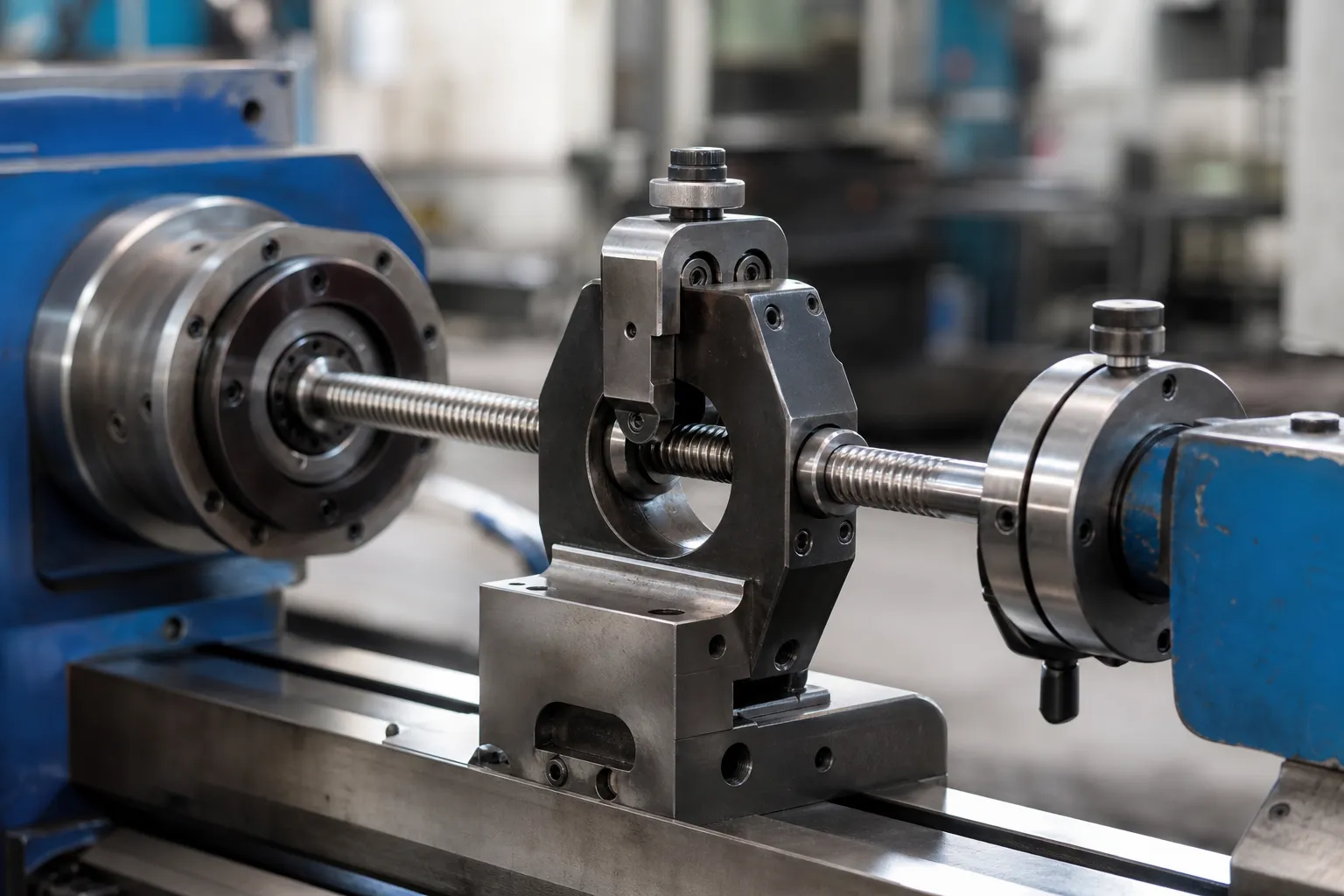
*Snímka zdrojového videa.* Ilustruje len koncept bodovej korekcie; ochrana drážok a limity sily vyžadujú reprezentatívnu validáciu vzorky.
Riadená korekcia a odpruženie
Narovnanie vyžaduje kontrolované nadmerné ohýbanie, aby elastické odpruženie vrátilo hriadeľ bližšie k cieľu. Požadovaný posun nie je univerzálne percento. Závisí to od stavu materiálu, priemer, lokálna geometria vlákna/koreňu, rozpätie podpery a prichádzajúci ohyb. Počiatočná korekcia musí byť preto konzervatívna a spresnená z odozvy nameranej vzorky.
Premeranie a triedenie
Po každej korekcii, všetky požadované body sa zmerajú znova s použitím rovnakého základu a podmienok podpory. Časť je akceptovaná len vtedy, keď je dohodnutá charakteristika v tolerancii. Časť, ktorá dosiahne overenú silu, mŕtvica, cyklus alebo limit konzistencie merania je klasifikovaný ako NOK alebo technická kontrola namiesto opakovaného stláčania.
Ultra tenký Ø3,5 × 508 mm inžinierske ovládacie prvky
Pomer L/D približne 145.1 robí z tejto rodiny kontrolné riziko v aktuálnom informačnom balíku. Stroj musí rozlíšiť skutočný trvalý ohyb od vychýlenia spôsobeného usporiadaním podpery, gravitácie, kontaktná sila alebo manipulácia. Počas nakladania môžu byť potrebné dlhé vodiace lišty, ale musia sa uvoľniť alebo lokalizovať opakovane počas merania tak, aby nezakrývali prirodzený stav hriadeľa.
| Riziko | Možný efekt | Kontrola overenia |
|---|---|---|
| Vlastná hmotnosť medzi podperami | Zdanlivý ohyb sa mení s rozostupom opory alebo postojom | Definujte miesta podpory a korelujte meradlo výroby |
| Kontaktná sila sondy | Senzor mení polohu, ktorú meria | Sonda s nízkou silou alebo overená bezkontaktná metóda |
| Dlhý chvost bez podpory | Vibrácie a nestabilné uhlové čítanie | Ďalšie riadené podpery alebo alternatívna orientácia |
| Malé korekčné okienko | Jeden ťah obráti alebo lokalizuje ohyb | Jemné rozlíšenie posunu a stupňovité korekcie |
| Kontakt závitu | Poškodenie hrebeňa alebo merací signál súvisiaci s výškou tónu | Chránené nástroje a metóda merania schválená výkresom |
| Manipulácia | Zamotanie, škrabanie alebo nový ohyb pred meraním | Riadené nakladanie, riadené skladovanie a separácia dielov |
Odporúčaná konfigurácia stroja a bunky
| modul | Navrhovaná požiadavka | Hranica projektu |
|---|---|---|
| Koncepcia stroja | Presná automatická stanica na vyrovnávanie bodov | Konečná platforma vybraná po testovaní oboch rodín |
| Meranie | Kontakt s nízkou silou alebo overený bezkontaktný systém hádzania | Musí reprodukovať dohodnutý údaj a metódu merania |
| Rotácia | Presné skľučovadlo, strediská alebo podpery žurnálu | Samotný závit sa nepovažuje za základ |
| Podporuje | Nastaviteľné, kontúrované, vymeniteľné kontakty | Samostatné rozloženie pre krátke a ultratenké skrutky |
| Stlačte Unit | Jemná servoelektrická alebo presná hydraulická korekcia | Rozsah sily a zdvihu určený zo vzoriek |
| Nástroje | Mäkké/chránené baranidlo a podporné vložky tam, kde je to vhodné | Materiál a kontaktné značky vyžadujú schválenie |
| Ovládacie prvky | Modelové recepty, kontroly hodnovernosti a korekcie v uzavretej slučke | Žiadny zdieľaný recept bez overenia |
| Načítava sa | manuál, zásobníkom alebo automatizovanou manipuláciou | Vybrané zo stability dielu, objem a takt |
| Údaje | Vstupné/konečné čítania, počet korekcií a OK/NOK | Úroveň sledovateľnosti definovaná požiadavkami zákazníka |
| Bezpečnosť | Stráženie, zámky, alarmy preťaženia a abnormálneho merania | Vyžaduje sa pre konfiguráciu výroby |
Benchmarking náhrady za existujúce vybavenie
Zákazník hlási predchádzajúce použitie zariadenia Galdabini a posudzuje alternatívny zdroj. Pri zodpovednom porovnaní by sa mala použiť rovnaká reprezentatívna dávka vzorky, rovnaký údaj a meradlo, rovnakú prípustnú toleranciu a rovnaké kritériá poškodenia povrchu. Mal by tiež porovnať mieru korekcie, čas cyklu, prechod, falošne odmieta, požiadavky na prístup k údržbe a údaje.
V návrhu by sa nemalo uvádzať, že názov značky je „ekvivalentný k Galdabini“., fotografiu alebo rozsah menovitého priemeru. Ekvivalencia môže byť podporená len zdokumentovaným benchmarkom alebo výsledkom FAT/SAT na dohodnutých častiach.
| Referenčná položka | Požadovaný dôkaz |
|---|---|
| Korelácia meraní | Rovnaký dátum, meracie body a porovnanie kalibrovaného meracieho prístroja |
| Finálna kvalita | Výsledky pred/po v reprezentatívnych normálnych a najhorších prípadoch |
| Ochrana závitu | Vizuálne, rozmerová a funkčná prijateľnosť po narovnaní |
| Schopnosť procesu | Dostatočná veľkosť vzorky po oprave receptúry je stabilná |
| Priepustnosť | Časovaný cyklus vrátane zaťaženia, iterácií, vykládka a normálne zastávky |
| Zmena | Predvádzaný prepínač nástrojov a receptúr pre obe veľkosti |
| Spoľahlivosť | Alarm, kontrola údržby a opakovateľnosti počas skúšky alebo akceptácie |
Validácia projektu pred konečnou cenovou ponukou
Reprezentatívne vzorky by mali pokrývať obe geometrie, normálne a najhoršie prichádzajúce zákruty, každý materiál alebo stav tepelného spracovania a všetky relevantné varianty závitu/objímky. Každý pokus by mal zaznamenať stav podpory, dátum merania, prichádzajúci priebeh, korekčná poloha, sila/úder, ak je to možné, konečný výsledok, počet korekcií a akýkoľvek povrchový efekt. A zdokumentované rovnanie vzor-test akceptačný plán by mali definovať, ako sa tieto výsledky stanú schvaľovacím rozhodnutím.
Ø3,5 × 508 Pred začatím korekčných pokusov by sa mala skupina vzoriek v mm samostatne vyhodnotiť z hľadiska opakovateľnosti merania. Ak meradlo nedokáže rozlíšiť ohyb dielu od podpery- alebo sondou vyvolané vychýlenie, výsledok vyrovnania nie je možné spoľahlivo zaručiť.
Informácie potrebné pre návrh vyrovnávania vodiacej skrutky
Uveďte výkres skrutky, potvrdenie, či tieto dve veľkosti sú samostatné modely, množstvo vzorky a ročný objem, materiál a tvrdosť, tvar nite a olova, etapa tepelného spracovania a obrábania, polohy ložiskového žurnálu a stredu, distribúcia prichádzajúceho výbehu, konečná charakteristika a údaj, povolené podporné/tlačové zóny, chránené povrchy, etapa montáže motora, poraziť cieľ, smer nakladania a reprezentatívne vzorky.
Tieto vstupy umožňujú riešiteľovi vybrať metódu merania, rozloženie podpory, uznesenie tlače, bezpečné korekčné okno, náradia, manipulačný a akceptačný plán bez hádania len z hodnotenia motora alebo videa.
Technická referenčná základňa
- Presnosť guľôčkovej skrutky THK a meranie montážnej plochy opisuje hádzanie vzhľadom na os podpery a meranie v niekoľkých axiálnych polohách.
- Návod na kontrolu guľôčkových skrutiek KURODA uvádza hádzanie ložiska a celkové zakrivenie hriadeľa skrutky medzi položkami kontroly na základe výkresu.
- Vedenie vyrovnávania vodiacej skrutky Roton odporúča riadené lisovacie vyrovnávanie a obuv na ochranu nití.
- Aplikácie obrobkov MAE identifikuje dlho, tenké guľôčkové skrutky ako presné vyrovnávacie aplikácie.
Tieto zdroje podporujú iba inžinierske princípy. They are not evidence of achieved results for the customer's reported parts.
FAQ
Môže jeden stroj vyrovnať oba Ø6,35 × 75 mm a Ø3,5 × 508 vodiace skrutky mm?
Možno, ak je rozsah merania, podporuje, uznesenie tlače, manipulačné a korekčné okienko pokrývajú obe rodiny. Rozdiel L/D je dostatočne veľký na to, aby sa to preukázalo samostatnými skúškami nástrojov a vzoriek, nepredpokladá sa len z priemeru.
Má 2.33 VDC at 1.5 Menovitý výkon motora ovplyvňuje vyrovnávaciu silu?
Nie. Pomáha identifikovať zostavu krokového motora, ale nedefinuje materiál skrutky, ohybová tuhosť, geometria závitu, rozpätie podpery alebo vyrovnávacia sila.
Mala by byť skrutka narovnaná pred alebo po montáži motora?
Holý skrutkový hriadeľ je preferovanou počiatočnou fázou, pretože zabraňuje prenosu korekčného zaťaženia na ložiská motora alebo spojky. Oprava montáže je možná len s vyhradeným prípravkom a schváleným plánom validácie zaťaženia a hádzania ložiska.
Môže stroj merať priamo na závite?
Len s metódou overenou pre tvar závitu a konečnú kontrolu. Hladké denníky, ložiskové sedadlá, stredísk, majstrovský orech, obvod matice alebo vhodná optická metóda môže poskytnúť spoľahlivejšiu funkčnú referenciu.
Ako sú vlákna chránené pri lisovaní?
Receptúra definuje schválené podporné a lisovacie zóny, zatiaľ čo tvarované vymeniteľné kontakty rozdeľujú záťaž. Vhodné môžu byť mäkké materiály topánok, ale konečný materiál a geometria musia prejsť kontrolou povrchu a funkčnosti skutočných skrutiek.
Čo dokazuje projektové video?
Zobrazuje vodiacu skrutku so závitom v kompaktnej rotačnej/podpornej/korekčnej stanici. Nepreukazuje uvádzané rozmery, zostava motora, automatické kŕmenie, čas cyklu, konečná tolerancia alebo výsledok dlhých skrutiek.
Dá sa zaručiť, že alternatívny stroj bude rovnocenný s existujúcim zariadením Galdabini??
Iba po referenčnej hodnote rovnakej vzorky s použitím rovnakého dátumu, meradlo, tolerancie, povrchové kritériá a výrobné podmienky. Bez tohto dôkazu by sa nemala sľubovať rovnocennosť medzi značkami.
Záver
Vyrovnanie vodiacej skrutky závisí od funkčného základu, ochrana závitu a korekčné okno, ktoré zodpovedá skutočnej geometrii. Hlásený Ø6,35 × 75 mm a Ø3,5 × 508 mm diely predstavujú veľmi odlišné problémy s meraním a podporou, preto by sa s nimi malo zaobchádzať ako s dvoma overenými receptami, aj keď jeden modulárny stroj nakoniec pokrýva oba.
When you move from reading to quoting on lead screw work, a manual vs automatic selection logic a ROI puzdro pre automatické vyrovnávanie will save a round of emails.
Pošlite svoje kresby, materiál a tvrdosť, podrobnosti vlákna, definície prichádzajúceho a cieľového hádzania, výrobné štádium, objem a reprezentatívne vzorky na preskúmanie uskutočniteľnosti. StraighteningTech vyvinie meranie, náradia, koncept korekcie a akceptácie v súvislosti s evidenciou obrobku, a nie odporúčanie zariadenia len na základe menovitého výkonu motora alebo menovitého priemeru.