
Длинная шаровая шпилька не представляет собой простой круглый стержень и не представляет собой законченный узел рулевой тяги.. Он сочетает в себе тонкий хвостовик с высоконагруженной шаровой головкой., радиус перехода и, в зависимости от стадии производства, квартиры, конус, резьба или готовые поверхности подшипников. Метод правки должен корректировать годный к использованию хвостовик без перекатывания или давления на функциональные зоны, не предназначенные для контакта..
По этой причине, Решение по выпрямлению длинных шариковых шпилек начинается с чертежа и маршрута изготовления. Роликовый процесс может быть эффективен для получения достаточно однородного хвостовика и распределенной кривизны.; Коррекция измеренной точки может быть безопаснее, если полезная длина роликового контакта коротка или когда деталь имеет готовые элементы, требующие избирательного контакта.
Шаровой шпилька, Шаровой шарнир и рулевая тяга — это разные продукты
ZF описывает шаровой шарнир шасси как стальной шаровой палец, вращающийся в смазанной чашке подшипника внутри корпуса.. ZF также описывает рулевую тягу как рычажный механизм, содержащий внутренние и внешние шаровые шарниры, соединенные регулировочной резьбой.. Заготовки на фото проекта представляют собой отдельные заготовки длинных шариковых шпилек., не собранные шаровые опоры или рулевые тяги.

Изображение подтверждает настоящие длинные шариковые заготовки с черной поверхностью, шаровыми головками и тонкими корпусами.. Он не устанавливает марку стали., твердость, размеры, окончательная геометрия или приемка заказчику.
| Продукт/функция | Выпрямление значения |
|---|---|
| Холоднокованая заготовка шарового пальца | Масштаб и вариации размеров влияют на кормление, контакт и измерение |
| Шаровая головка | Необходимо направлять или очищать, не повреждая будущую опорную поверхность. |
| Переход от головы к хвостовику | Высокая геометрическая и усталостная значимость; обычно исключается из концентрированной коррекции |
| Равномерный цилиндрический хвостовик | Зона-кандидат для валидированного непрерывного контакта роликов |
| Плоский, функция шлица или гаечного ключа | Изменяет вращение и может прервать поддержку роликов. |
| Конус или резьба | Функциональная зона сборки, требующая защищенного обращения и определения измерений |
| Готовая/закаленная поверхность | Требуется отметка на поверхности, контроль остаточных напряжений и трещин |
Выберите этап производства перед машиной
Один и тот же компонент может вести себя по-разному на каждом этапе производства..
| Этап | Типичная причина выпрямления | Главный элемент управления |
|---|---|---|
| После холодной ковки | Устраните изгиб, возникший при формовке/выталкивании, и подготовьтесь к механической обработке. | Шкала, разброс по размерам и обширные, но четко определенные зоны контакта |
| После черновой обработки | Восстановить геометрию перед отделкой | Защита эталонных диаметров и сохранение припусков на обработку |
| После термической обработки | Исправление искажений, вызванных термообработкой | Профиль твердости, пружинение, риск трещин и ограниченное окно коррекции |
| После шлифовки/полировки | Встречайте окончательную геометрию | Очень строгие требования к поверхностному контакту и корреляции измерений. |
| После покрытия/покрытия | Обычно исключительный случай | Повреждение покрытия, риск, связанный с водородом, и одобрение клиентов |
Фотографии проекта кажутся темными., незавершенные заготовки и роликоправильная станция. Они не подтверждают точную стадию производства.. В предложении должен быть указан этот этап, прежде чем определять инструменты или гарантированные результаты..
Требуемые входные данные проекта
| Вход | Необходимая информация |
|---|---|
| Рисунок | Редакция, контролируемые зоны, дата, допуски и запрещенные зоны контакта |
| Геометрия | Диаметр шара, диаметры хвостовика, длина, переход, квартиры, конус и резьба |
| Материал | Марка стали, состояние ковки и соответствующие механические свойства |
| Термическая обработка | Сквозная/индукционная/цементируемая закалка, профиль твердости и последовательность обработки |
| Поверхность | Шкала, механическая обработка, шлифование, дробеструйная обработка, покрытие и допустимые отметки |
| Входящий изгиб | Величина, направление и осевое распределение по репрезентативным партиям |
| Итоговая характеристика | Прямолинейность хвостовика, прямолинейность производной оси, результат биения или функциональной сборки |
| Производственная цель | Часть смеси, выход, загрузка, контрольный отбор проб и замена |
На предыдущей странице упоминался диапазон 20–45 HRC и 0.2 мм мишень. Они остаются входными данными до тех пор, пока фактическое состояние детали не изменится., характеристика, контролируемая длина и толщина документированы.
Определите, что означает «прямолинейность 0,2 мм»
| Возможное требование | Требуемое определение |
|---|---|
| Прямолинейность элемента поверхности хвостовика | Какой элемент поверхности и контролируемая осевая длина |
| Производная прямолинейность оси хвостовика | Как строится ось из измеренных сечений |
| Радиальное биение | База вращения, положение зонда и угловая выборка |
| Выравнивание шара по хвостовику | Конструкция шарового центра и ссылка на хвостовик |
| Соотношение конус/резьба | Ось даты, функциональный калибр и допустимые вариации |
| Максимальный зазор на приспособлении | Расстояние между опорами, метод ориентации и калибра |
Циферблатный индикатор на опорном приспособлении, испытание на биение по центру и оценка прямолинейности по всему профилю не дают взаимозаменяемых результатов. При приемке машины необходимо использовать характеристики, специфичные для чертежа, и коррелировать с окончательным размером, указанным заказчиком..
Когда роликовое выпрямление является кандидатом
Двухвалковые правильные машины широко используются для круглых прутков., и производители описывают их как использование роликов противоположной формы для сгибания и вращения прутка в ходе непрерывного процесса.. Даниэли также отличает двухвалковый, многовалковые и другие устройства для правки прутков для различных применений. Эти принципы поддерживают семейство процессов.; они не доказывают, что каждый шаровой палец может проходить через один и тот же комплект роликов..
Роликовый процесс оценивается, когда:
- хвостовик имеет достаточно равномерную длину контакта;
- шаровая голова, переход, лыски и торцевые элементы можно безопасно очищать или направлять;
- изгиб распределен и может быть скорректирован с помощью проверенной кривой крена и давления;
- непрерывное вращение/контакт разрешены спецификациями поверхности;
- часть не может убежать, член или застревание, когда голова приближается к направляющей;
- образцы демонстрируют приемлемую геометрию, состояние поверхности и металлургическое состояние.
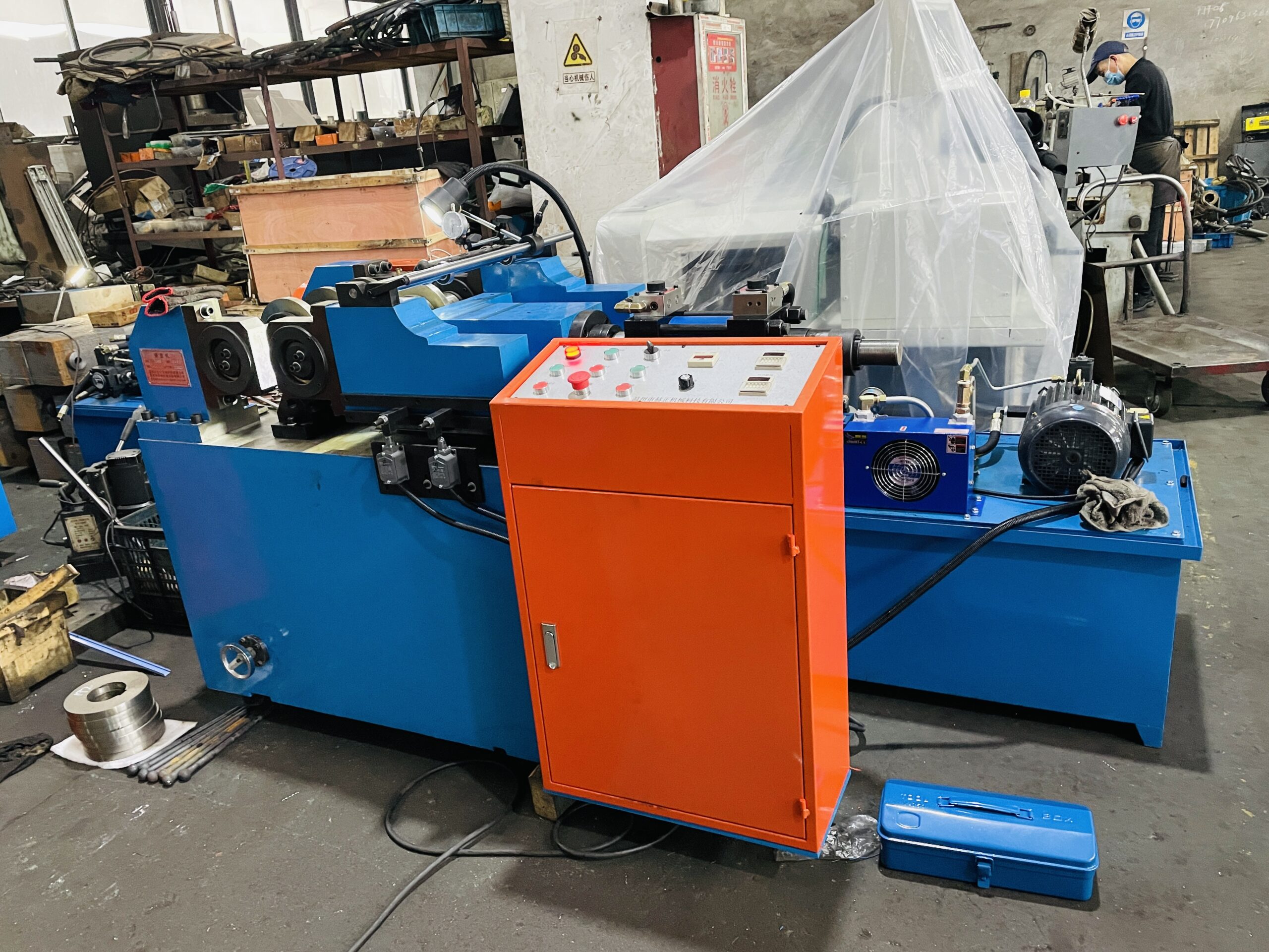
Фото проекта подтверждает станок роликового типа., направляющие и зона измерения. Это не доказывает конкретное количество роликов, автоматическое управление с обратной связью, скорость или точность.
Рекомендуемый процесс роликовой правки
1. Определить утвержденный вариант и стадию
Оператор подбирает рецепт точной поковки, длина, диаметр хвостовика, состояние твердости и состояние поверхности. В комплект валков предотвращается попадание смешанных деталей или неправильной стадии производства..
2. Проверьте входящую заготовку
Детали с трещинами, складки, серьезное повреждение головы, чрезмерный изгиб или размеры за пределами валидированного окна отделяются перед выпрямлением. Правка не является методом ремонта дефектов ковки..
3. Ориентируйте и направляйте шаровую головку
Входная направляющая обеспечивает устойчивость шпильки, позволяя при этом утвержденной зоне хвостовика входить в ролики.. Шаровая головка и переход остаются за пределами опасного контакта с линией.. Если в состав части входят квартиры, подтверждено их влияние на ротацию и кормление.
4. Примените проверенную настройку ролика
Профиль рулона, угол пересечения, зазор/давление, положение направляющей и скорость подачи контролируются рецептом. Настройка должна обеспечивать достаточную пластическую коррекцию хвостовика без чрезмерного изменения диаметра., полировка, отступ, риск повышения температуры или остаточного напряжения.

5. Измерьте, используя согласованную точку отсчета
Деталь измеряется на указанных станциях и направлениях.. В зависимости от рисунка, это может быть автоматическая проверка, внешний манометр, оптический профиль или испытание на биение на основе вращения. Видимое расположение индикаторов на фотографии поддерживает измерение., не автоматическое заявление о окончательной проверке.
6. Решите пройти, переработать или отклонить
Один дополнительный проход разрешен только в том случае, если он включен в утвержденный рецепт.. Неограниченное многократное прокатывание может изменить состояние поверхности., диаметр и остаточное напряжение. Детали за пределами утвержденного окна помещаются на карантин для инженерной проверки..
7. Проверьте состояние, а также геометрию
План качества может включать поверхностный осмотр., проверка размеров, магнитно-порошковый контроль или проверка на другие трещины, проверка твердости и последующие испытания на механическую обработку/сборку. Точные методы следуют материалу., этап изготовления и чертеж заказчика.
Видео о выпрямлении настоящей длинной шариковой шпильки
Следующее общедоступное видео связано с оригинальной статьей о длинной шариковой шпильке и показывает оборудование для выпрямления роликов проекта.. Он поддерживает только концепцию видимого процесса.. Это не доказывает ранее сказанное 0.2 мм результат, 20Диапазон –45HRC, Индийский клиент, увеличение производства или оценка клиентов.
Выпрямление роликов или коррекция измеренной точки?
| Фактор принятия решения | Выпрямление роликами может быть предпочтительнее, если | Точечная коррекция может быть предпочтительнее, когда |
|---|---|---|
| Распределение изгиба | Кривизна распределена по равномерному хвостовику | Можно измерить одну или несколько локализованных высоких точек. |
| Контактная зона | Допускается постоянный контакт хвостовика | Разрешены только выбранные зоны поддержки и пресса. |
| Конечная геометрия | Головка и другие функции могут очистить систему рулонов/направляющих. | Сложные концы делают непрерывный проход небезопасным |
| Поверхность | Контакт роликов и любой эффект полировки приемлемы. | Готовые поверхности требуют локализованного защищенного инструмента. |
| Измерение | Достаточно до/после или выборочного контроля | Необходимо измерение с обратной связью после каждой коррекции. |
| Часть смеси | Стабильный, семейство большего объема | Детали меньшего объема или с большим количеством смеси по специальным рецептам |
Ни один из методов не является универсально «лучшим». Выборочное исследование также может показать, что правку следует перенести на более раннюю стадию производства, а не подвергать готовый шаровой палец любому из процессов..
Голова, Переход и защита поверхности
| Риск | Контроль |
|---|---|
| Вмятина или царапина на поверхности шара | Очистите шар от рабочих валков и используйте утвержденные направляющие. |
| Переходная трещина | Исключить радиус из сосредоточенной нагрузки; добавить обязательную проверку трещин |
| Вмятина на хвостовике или изменение диаметра | Профиль матч-ролла, давление и состояние поверхности; мера после обработки |
| Плоская или нить цепляет направляющую | Определите ориентацию/зазор и используйте инструменты для конкретного варианта. |
| Повреждение затвердевшего слоя | Проверка контактного напряжения и предела коррекции на образцах производственного эквивалента. |
| Перегрев или чрезмерная полировка | Ограничивайте скорость/давление/проходы и следите за согласованным состоянием |
| Часть выходит непредсказуемо | Используйте позитивные руководства, охрана и безопасный сбор |
Пример плана испытаний и приемки
Репрезентативные образцы
- наименьшая полезная длина роликового контакта и наибольшее соотношение головки к хвостовику;
- минимальный и максимальный диаметры хвостовика;
- все соответствующие условия ковки и термообработки;
- каждая квартира, сужаться, конфигурация резьбы и конца;
- части по реальному распределению входящего изгиба;
- несколько партий, в которых окалина ковки, твердость или упругость могут варьироваться.
Требуемые доказательства
| Записывать | Свидетельство о приемке |
|---|---|
| Идентификация детали | Редакция чертежа, вариант, материал, этап и партия |
| Входящая геометрия | Характеристика, исходное значение, позиции и ценности |
| Рецепт | Роллы, гиды, зазор/давление, угол, скорость и лимит прохода |
| Окончательная геометрия | Та же определенная характеристика плюс корреляция с оценкой клиента |
| Размеры | Диаметр хвостовика и функциональные характеристики остаются в пределах допуска. |
| Поверхность/переход | Утвержденный результат визуального контроля и проверки на наличие трещин |
| Производственные испытания | Измеренный цикл, джемы, переключение, осмотр и наличие |
Исследование должно включать части, расположенные вблизи предполагаемой границы процесса., не только несколько простых образцов.
Область автоматизации
| Уровень | Типичный объем |
|---|---|
| Руководство | Операторские нагрузки, выполняет утвержденный пропуск и выгружает для проверки |
| Помогал | Поддержка подачи/выгрузки и управляемый сбор |
| Автоматический | Разделение, ориентация, прокатка, измерение и сортировка результатов |
| Прослеживаемый | Идентификация детали/партии, рецепт, записи измерений и процессов |
Автоматическая загрузка зависит от того, запутываются ли шаровые головки., требуют ли плоские или конусные ориентации ориентации и разрешен ли контакт с поверхностью. Автоматизация и отслеживаемость — это упорядоченные области применения., не предположения по фотографии машины.
Что не является универсальным обещанием
Перед просмотром чертежа и проверкой образца, это решение не обещает:
- 0.2 мм прямолинейность для неопределенной характеристики;
- одно технологическое окно на каждую деталь 20–45 HRC;
- пригодность для шаровых шарниров в сборе или рулевых тяг в сборе;
- безопасный контакт роликов с готовыми шариками, сужается, нити или покрытия;
- одна настройка роликов для любой длины и диаметра;
- ноль трещин, знаки, изменение диаметра или эффекты остаточного напряжения;
- фиксированное время цикла, увеличение выпуска или снижение затрат;
- результат или отзыв индийского клиента без авторизованных записей.
Связанные приложения
Ознакомьтесь с нашими Решения для выпрямления крепежа и инструментов и Машина для выпрямления шариковых шпилек для смежных приложений и оборудования. Если компонент имеет функцию рулевой рейки или рулевой тяги в сборе., это требует отдельного исследования исходных данных и функционального риска.
Информация для отправки предложения
Большинство запросов на выпрямление длинных шаровых шпилек обрабатываются быстрее, когда покупатель приходит с руководство по выбору станка для валов, трубы и профили уже отработано и целевой диапазон от разбивка цен на правильные машины.
Отправьте чертеж и доработку, репрезентативные образцы, размеры шарика/хвостовик/перехода, детали лыски/конуса/резьбы, материал и маршрут термообработки, точный этап изготовления, состояние поверхности, распределение входящего изгиба, окончательная характеристика и исходные данные, датчик клиента, запрещенные контактные зоны, требование проверки трещин, цель вывода и предпочтительный метод загрузки.
Свяжитесь с StraighteningTech для выборочного исследования выпрямления длинного шарового пальца. Определим подходящий этап процесса, концепция роликовой или точечной коррекции, охраняемые зоны, метод измерения и свидетельство приемки для фактического семейства деталей.
Часто задаваемые вопросы
Шаровая шпилька — это то же самое, что рулевая тяга??
Нет. Шаровая шпилька — это деталь внутри шарового шарнира.. Рулевая тяга — это рулевая тяга большего размера, которая обычно включает в себя шаровые шарниры и регулировочное соединение.. Это решение касается отдельных заготовок или деталей длинных шариковых шпилек..
Может ли шаровая головка проходить между правильными валками??
Не по умолчанию. Шарик и его переход работоспособны, высоконагруженные зоны. Инструмент обычно очищает или направляет их, пока утвержденный однородный хвостовик входит в валки.. Любой прямой контакт требует явного утверждения чертежа и проверки образца..
Могут ли детали, закаленные до 45 HRC выпрямляется роликами?
Возможно для конкретного материала, профиль твердости, геометрия и входящий изгиб, но одного количества недостаточно. Пружинный возврат, глубина корпуса, переходный стресс, риск растрескивания и допустимый контакт с поверхностью должны быть проверены.
Является 0.2 мм требование прямолинейности или биения?
Один только номер не может ответить на этот вопрос. На чертеже должна быть названа характеристика, контролируемая длина, исходное значение, Позиции измерения и метод оценки. Затем необходимо провести корреляционное исследование машины и датчика клиента..
Когда вместо этого следует рассматривать точечную коррекцию?
Когда изгиб локализован, полезная длина роликового контакта мала, сложные функции препятствуют безопасному непрерывному проходу или обработанные поверхности требуют выборочного инструмента и измерения с обратной связью.
Техническая справочная граница
- Шаровые шарниры ZF: https://press.zf.com/press/en/media/media_2252.html
- ZF рулевые тяги: https://www.zf.com/products/en/cars/products_65853.html
- Детали рулевого управления и шасси ZF: https://aftermarket.zf.com/sg/aftermarket-portal/our-portfolio/passenger-cars/products/steering-and-chassis-parts/
- Шаровые шарниры MOOG: https://www.moogparts.com/en-eu/products/suspension/ball-joints.html
- Выпрямительные машины Danieli: https://www.danieli.com/en/products/products-processes-and-technologies/ingot-casting_26_12.htm
- Двухвалковая правильная машина Mair Research: https://www.mair-research.com/en/two-roll-straightening-machine/
- Заготовки и приложения MAE: https://mae-group.com/en/workpieces-applications/
Эти ссылки поддерживают терминологию шаровых шарниров., Разнообразие условий материала и общие принципы правки роликами/давлением. Они не доказывают, что характеристики другого поставщика применимы к конфигурации StraighteningTech..