
O componentă de burghiu medical în trepte nu este un arbore uniform. Secțiunile sale cilindrice mari și mici, umerii, razele de tranziție, Capătul tăietor și capătul de antrenare pot avea fiecare un rol funcțional diferit, rigiditate și stare de contact admisibilă. Prin urmare, un sistem de îndreptare trebuie să măsoare și să corecteze piesa de prelucrat după secțiune, în loc să trateze întreaga lungime ca o singură bară rotundă simplă..
Obiectivul nu este pur și simplu de a micșora valoarea unui indicator. Procesul trebuie să păstreze caracteristicile funcționale, evitați încărcarea tranzițiilor vulnerabile și obțineți un rezultat care se corelează cu metoda de desen și inspecție a clientului.
De ce exercițiile medicale în trepte au nevoie de un proces dedicat
Familiile de foraje medicale variază foarte mult. Informațiile oficiale despre produs de la DePuy Synthes se referă la burghiele trepte utilizate cu opritoare de foraj, în timp ce Stryker listează burghie în diferite diametre și lungimi. Aceste referințe demonstrează diversitatea piesei de prelucrat; nu înseamnă că fiecare exercițiu medical are același material, geometrie sau cerință de acceptare.
Pentru un proiect de îndreptare, următoarele caracteristici modifică designul procesului:
| Caracteristica piesei de prelucrat | Consecință de îndreptare |
|---|---|
| Diametre cilindrice multiple | Fiecare secțiune poate necesita o poziție de măsurare diferită, intervalul de suport și limita de corecție |
| Umeri și raze de tranziție | Concentrarea locală a stresului face ca aceste zone de presare sau de sprijin implicite sărace |
| Secțiune lungă cu diametru redus | Rigiditatea la încovoiere mai mică mărește deviația gravitațională și sensibilitatea la forța de măsurare |
| Capăt tăiat sau dintat | Geometria de tăiere trebuie protejată de fălci, sonde și instrumente de corectare |
| Conduce, cuplaj sau caracteristică plată | Poate fi un datum funcțional, dar nu este automat o suprafață rotundă |
| Corp tratat termic sau finisat la suprafață | Springback, riscul de marcare și fisurare trebuie validat pe mostre reprezentative |

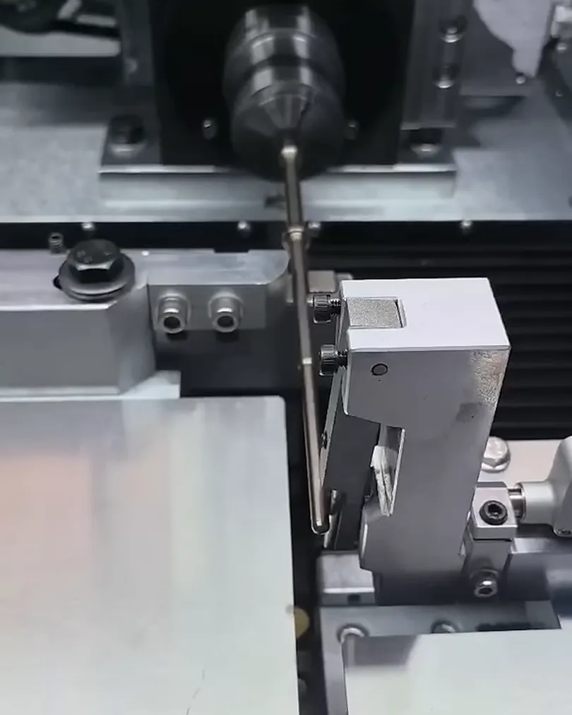
Acest cadru de proiect real arată o componentă în trepte lungă ținută la o stație de măsurare și corecție. Acesta confirmă aranjamentul piesei de prelucrat și al echipamentului, dar nu stabileşte material, dimensiuni, precizie sau timp de ciclu.
Definiți cerința de desen înainte de a selecta mașina
Cuvântul „dreptate” este adesea folosit pentru mai multe caracteristici diferite. ISO 1101 oferă limbajul pentru toleranța geometrică, dar desenul mai trebuie să identifice caracteristica reală și sistemul de date.
Înainte de o cotație sau o probă de probă, confirma dacă clientul are nevoie:
- rectitudinea axei unei secțiuni cilindrice;
- runout radial sau total indicat în raport cu jurnalele selectate;
- coaxialitate sau poziție între două secțiuni trepte;
- o cerință de plic de lungime completă;
- dreptate locală pe lungimea ecartamentului specificată;
- sau o cerință combinată care acoperă geometria și starea suprafeței.
Aceste cerințe nu sunt interschimbabile. O piesă de prelucrat poate prezenta o curgere acceptabilă la o secțiune, în timp ce o altă secțiune cu diametru redus rămâne în afara toleranței sale de tragere. De asemenea, este posibil să se îmbunătățească traseul unui indicator în timp ce se înrăutățește coaxialitatea dintre secțiuni dacă strategia de referință este greșită.
Intrările de proiect raportate nu sunt specificații finale
Aplicația sursă a descris aproximativ o piesă de prelucrat 230 mm lungime cu diametre raportate aproape 7.9, 6.9 şi 5.9 mm. De asemenea, a menționat a 0.05 mm țintă. Aceste valori sunt utile pentru planificarea unui exemplu de discuție, dar nu sunt tratate aici ca rezultate de producție verificate.
Înainte de aprobarea tehnică, clientul trebuie să clarifice:
| Intrare necesară | De ce contează |
|---|---|
| Desen și revizuire controlate | Previne construirea sculelor și inspecției în jurul geometriei învechite |
| Condiția materialului și a tratamentului termic | Determină rigiditatea, springback, riscul de fisurare si presiunea de contact admisibila |
| Etapa de fabricație | Definește caracteristicile de tăiere, acoperire, pasivarea sau finisarea finală există deja |
| Date și caracteristică | Determină sprijinul, locațiile de rotație și sonde |
| Distribuția inițială a îndoirii | Determină cursa de corecție necesară și dacă piesa este recuperabilă |
| Zone de contact interzise | Protejează umerii, caracteristici de tăiere, finisaje si suprafete functionale de cuplare |
| Indicator de client sau mostre de corelare | Face ca rezultatele mașinii să fie comparabile cu inspecția de recepție finală |
Strategia de măsurare specifică secțiunii
Sistemul de măsurare nu trebuie să presupună că o pereche de centre sau o suprafață cilindrică reprezintă piesa de prelucrat completă.
1. Stabiliți datele funcționale
Selectați suprafețele de referință din desen și logica de asamblare finală. Candidații potriviți pot include jurnale terminate, un diametru definit de tijă sau o caracteristică centrală controlată. Un umăr, flaut, relieful sau suprafața goală netratată nu ar trebui să devină referință doar pentru că este ușor de contactat.
2. Suport de control și efecte gravitaționale
Secțiunile lungi reduse se deviază sub propria greutate. Suportul orizontal nu elimină eroarea gravitațională. Metoda eșantionului trebuie să definească locații de sprijin, durata liberă, orientarea piesei de prelucrat, viteza de rotație și forța sondei. Mașina și gabaritul clientului ar trebui să inspecteze aceeași caracteristică în condiții corelate.
3. Măsurați mai mult de o secțiune
Utilizați stații axiale definite de desen pe diametrele relevante. O sondă trebuie să rămână pe un teren cilindric aprobat și nu trebuie să traverseze un umăr sau un relief în timpul măsurării. Dacă piesa conține o caracteristică non-rotundă, sistemul poate avea nevoie de indexare unghiulară sau de un alt senzor, mai degrabă decât de un indicator de contact convențional.

Cadrul video arată piesa de prelucrat lângă un ansamblu compact de detectare/corecție. Tipul exact de senzor și forța sunt specifice proiectului și trebuie confirmate în timpul proiectării mașinii.
Proiectarea zonei de corecție protejată
Corecția punctului ar trebui să acționeze numai asupra zonelor de oțel aprobate. Nu ar trebui plasat automat la cea mai mare abatere măsurată dacă acea locație este un umăr, raza de tranziție, caracteristică de tăiere sau altă zonă restricționată.
Creați o hartă de corecție înainte de programare:
| Tipul zonei | Regula implicită |
|---|---|
| Secțiune stabilă a corpului cilindric | Suport candidat sau zonă de corecție după evaluarea presiunii de suprafață |
| Secțiune lungă cu diametru redus | Utilizați creșteri de forță mai mici și limite de deplasare mai strânse |
| Umăr și raza de tranziție | Zona de contact interzisă sau special concepută |
| Tăiere, capăt dinţat sau canelat | Protejați de apăsarea directă și prindere puternică |
| Funcție de acționare/cuplare | Localizați numai cu unelte specifice variantei |
| Suprafață finisată sau acoperită | Utilizați material de contact validat și criterii de marcare |
Secvența de control ar trebui să aplice o corecție limitată, eliberați sarcina, remăsurați și actualizați următoarea acțiune. Această buclă de măsurare-corectare-remăsurare este esențială, deoarece backback-ul poate varia între secțiunile de diametru și loturile de tratament termic.
Exemplu de proces automat
O celulă automată de îndreptare a burghiului medical în trepte poate fi configurată în jurul următoarei secvențe:
- Încărcați sau primiți piesa de prelucrat fără a lovi elementele de tăiere și umăr.
- Confirmați prezența părții și, acolo unde este necesar, identitatea variantei.
- Localizați suprafețele de referință aprobate și controlați poziția axială.
- Rotiți piesa de prelucrat și măsurați secțiunile specificate cu suport controlat și forță de măsurare.
- Calculați direcția de îndoire și identificați o locație de corecție aprobată.
- Aplicați o corecție punctuală limitată cu monitorizarea forței sau a deplasării.
- Eliberare, rotiți și măsurați din nou secțiunile relevante.
- Repetați numai în cadrul iterației validate, forța și limitele de deplasare.
- Clasificați piesa ca fiind acceptată, respins sau care necesită o revizuire de inginerie.
- Înregistrați rezultatul final și datele de proces relevante atunci când este necesară trasabilitatea.
Celula reală poate utiliza încărcare manuală, o revistă, un robot sau o altă metodă de transfer. Nivelul de automatizare ar trebui să urmeze familia de piese, dimensiunea lotului, cerințele privind stabilitatea orientării și curățenia, mai degrabă decât să fie presupuse dintr-un videoclip demonstrativ.
Video de îndreptare cu burghiu medical în trepte real
Următorul videoclip de pe canalul Mașină de îndreptat arată o componentă lungă de burghiu medical la o stație automată de măsurare și corecție.
Videoclipul demonstrează mișcarea echipamentului și piesa fizică de prelucrat. Nu este un raport de inspecție și nu dovedește o toleranță universală, rata de producție, randamentul sau acceptarea clientului.
Validarea și acceptarea eșantionului
Un studiu cu eșantion reprezentativ este baza corectă pentru confirmarea fezabilității. Ar trebui să includă cele mai proaste combinații credibile de diametru, lungime, starea materiala, îndoire inițială și starea suprafeței.
Înregistrare de probă recomandată
| Înregistra | Conținut minim |
|---|---|
| Identitatea părții | Numărul desenului, revizuire, lot și etapa de fabricație |
| Geometrie de intrare | Caracteristică, datum, statii axiale si valori masurate |
| Setări de proces | Posturi de sprijin, zone de corectare, limitele de forță/deplasare și numărul de iterații |
| Geometria finală | Rezultate de la mașină și gabaritul corelat al clienților |
| Starea suprafeței | Marci, denivelări, deteriorarea stratului de acoperire și inspecția caracteristicilor de tăiere |
| Stare materiala | Dovezi de duritate sau tratament termic, atunci când este relevant |
| Excepții | Piese respinse, limitează încălcările și dispozițiile tehnice |
O țintă raportată, cum ar fi 0.05 mm nu poate deveni o garanție a mașinii până la caracteristica, datum, metoda de masurare, starea inițială și rezultatele eșantionului reprezentativ sunt convenite.
Limita calității dispozitivului medical
ISO 13485 definește cerințele de management al calității pentru dispozitivele medicale. In Statele Unite, Regulamentul FDA privind sistemul de management al calității a intrat în vigoare în februarie 2, 2026 și încorporează ISO 13485:2016 prin referire.
O mașină de îndreptat poate sprijini procesul controlat de un client prin rețete, niveluri de acces, planificarea calibrării, înregistrările rezultatelor și controlul modificărilor. Aparatul în sine nu certifică produsul clientului, validarea întregului proces de fabricație sau stabilirea conformității cu reglementările. Aceste responsabilități rămân în sarcina producătorului legal și a sistemului său de calitate.
Această soluție se referă la componentele din etapa de fabricație. Nu este o propunere de reparare sau reprocesare a burghiilor chirurgicale uzate.
De ce avem nevoie pentru o propunere de exercițiu medical în trepte
Whether you are upgrading an existing stepped medical drill line or buying new, cel straightener selection walkthrough iar cel budget picture for a straightening machine frame the trade-offs before you talk to suppliers.
Trimiteți următoarele informații pentru revizuire de inginerie:
- desen și revizuire;
- material, tratament termic și starea suprafeței;
- etapa de fabricație la care este necesară îndreptarea;
- secțiuni de diametru, lungimea totală și geometria umerilor;
- caracteristică definită de desen, data și limita de acceptare;
- distribuția inițială a îndoirii și pragul de respingere;
- zone de contact interzise;
- metoda de inspecție a clienților și eșantioanele de corelare disponibile;
- volumul de producție necesar și preferința de încărcare;
- trasabilitate, rețete și cerințe de export de date.
Echipa noastră va folosi aceste intrări pentru a defini un test eșantion, conceptul de măsurare, harta de corectare și configurația mașinii.
Întrebări frecvente
Un program poate acoperi mai multe dimensiuni de burghie medicale în trepte?
Eventual, dar fiecare variantă are nevoie de o rețetă controlată și un localizator compatibil, sprijin, statie de masurare si harta zonei de corectie. Lungimea totală similară nu dovedește că sculele pot fi partajate.
Poate mașina să garanteze 0.05 mm?
Nu numai de la o valoare țintă. Caracteristica, datum, ecartament, îndoire inițială, starea materialului și rezultatele probei trebuie definite înainte de a se lua un angajament de toleranță.
Îndreptarea va deteriora umerii sau suprafața finisată?
Soluția este concepută pentru a evita încărcarea directă pe caracteristici restricționate și pentru a controla presiunea de contact. Recepția finală a suprafeței necesită încă o inspecție reprezentativă a probei.
Este același proces ca îndreptarea unei tije medicale uniforme?
Nu. Diametrele multiple modifică rigiditatea, transfer de date, locațiile sondelor și zonele de corecție permise. Procesul trebuie să fie specific secțiunii.
Discutați piesa dvs. de lucru
Revizuiește-ne Pagina de aplicație Medical Drill şi Soluții pentru dispozitive medicale, sau contactați echipa noastră de soluții de îndreptare cu un desen și eșantion de informații.