
An ejector sleeve is a thin-walled tubular mold component: it ejects a molded boss or column around a stationary core pin, and in some molds it also shuts off on the core to form the part. This page is about straightening the sleeve itself — not the solid ejector pin. If you are looking for the pin process, see the ejector pin straightening solution; the sleeve is a different component with a different failure logic, and the two are often confused.
Because an ejector sleeve is a tube — typically H13/SKD61, wall thickness sometimes below a millimeter — a bend does not simply misalign it. It changes the running fit between the inner bore and the core pin and between the outer diameter and the mold plate simultaneously, producing bind, galling, flash at the boss, and seizure that snaps the core pin inside it. Straightening a sleeve is therefore a wall-integrity problem as much as a geometry problem.
An ejector sleeve straightening solution has to answer five questions before machine selection:
- Is this a new-production sleeve between heat treatment and grinding, or a sleeve from a maintained mold?
- Which features define the datum — the outer running diameter, the bore on the core pin, or the end faces?
- Is the deviation a centerline bow, an out-of-round (“egg-shaped”) starea peretelui, a bore-to-OD concentricity error, or distortion at the flange?
- Which correction route is approved — point-press straightening with protected tooling, or replacement for thin walls?
- How will released straightness, wall roundness and free running on the core pin be verified?

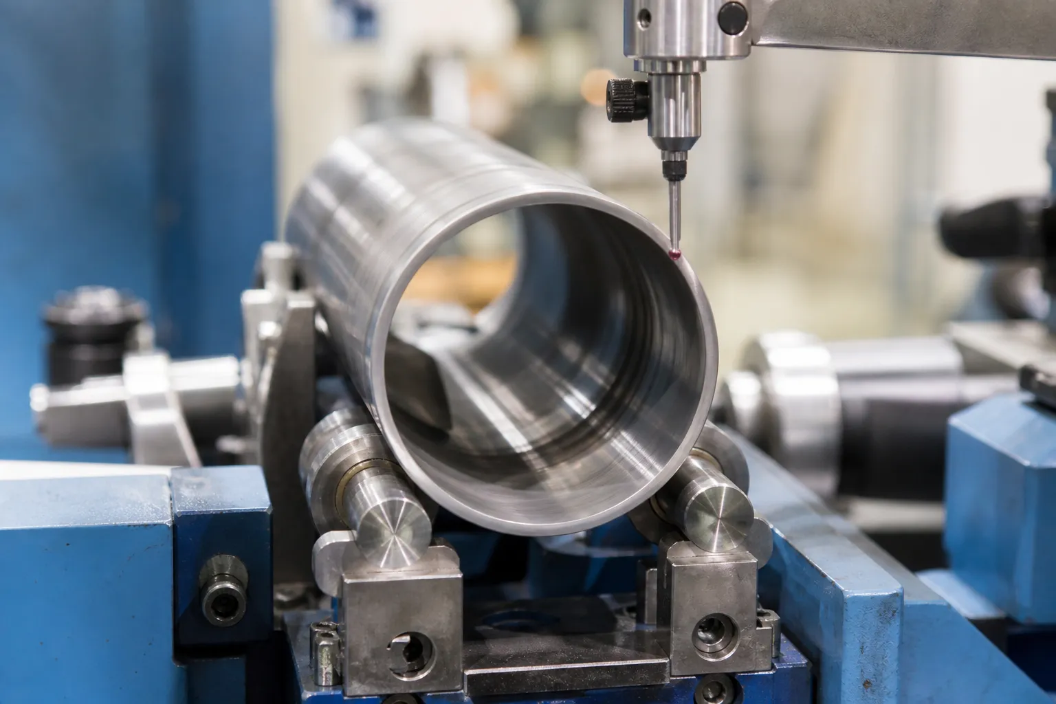
*Representative workshop photograph. Actual sleeve dimensions, wall thicknesses and correction limits follow the component drawing and a validated process study.*
Ejector Sleeve vs Ejector Pin: Why the Processes Differ
| Aspect | Ejector Pin (solid) | Ejector Sleeve (tubular) |
|---|---|---|
| Structura | Solid ground round pin | Thin-walled tube running over a core pin |
| Typical failure mode | Bend, wear on running diameter, sticking | Out-of-round walls, bore/OD fit loss, galling on the core pin, flange distortion |
| Correction risk | Springback, marcarea suprafeței | Wall ovality or collapse, bore damage, concentricity loss |
| Acceptance test | Corectitudine + running fit in plate | Corectitudine + roundness of both surfaces + free slide on the actual core pin |
A solid pin can be point-pressed like any slender shaft. A sleeve must be supported and loaded so the thin wall neither ovalizes locally under the press point nor collapses; that usually means shaped, full-contact support tooling matched to the outer diameter and very conservative load steps. The general mechanics of thin-wall handling are covered in thin-wall tube straightening without collapse.
What the Search Results Show
Rezultatele DataForSEO pentru ejector sleeve straightening return sleeve catalogs (PCS, MISUMI, HASCO, Meusburger), an ejector sleeve failure-mode article from the mold component trade press, and one firearms forum thread about straightening a rifle ejector rod. No straightening machine vendor currently addresses the term. The trade article’s findings match shop experience: tool steel sleeves fail by going out of round, galling, and size/shape change linked to retained austenite from heat treatment — which tells us exactly what a straightening process must screen for before, during and after correction.
Define the Datum Chain
A sleeve has (at least) three functional surfaces: the outer diameter that runs in the mold plate bores, the inner bore that runs on the core pin, and the flange/end faces through which the ejector force is transmitted. The functional requirement is free, centered travel over the core pin through the full ejection stroke — so the governing measurement is bore-to-OD concentricity plus straightness of both, not a single outer-diameter runout number.
The measurement plan should record:
- outer-diameter straightness and roundness, section by section;
- bore straightness and roundness — bore errors hide completely under an OD-only check;
- bore-to-OD wall concentricity (wall thickness variation around the circumference);
- flange faces square to the axis and flat;
- vent holes and side-wall ports present per drawing (they relieve vacuum at part release);
- starea suprafeței: galling, punctare, resin transfer, heat checking.
Înghețați etapa procesului
After Heat Treatment — the Main Case
Hardened H13/SKD61 sleeves bow and, critically, can go out of round. Straightening between heat treatment and finish grinding is the highest-value window: grind stock still exists on both surfaces, and the finish operations restore final size, roundness and finish. Springback is high and the thin wall fails locally before the whole part yields, so load steps must be small and validated on samples — the stage logic in îndreptarea după tratamentul termic applies. Note that if the material route is the source of shape change (retained austenite), no amount of pressing gives a stable sleeve — the correction map will drift, and the disposition is material process correction, not more pressing.
După terminarea șlefuirii
Both surfaces are now finished running fits. Correction is restricted to gentle point-pressing with shaped supports on approved zones, and only for residual errors the grinder could not remove. If bore-to-OD concentricity is out after grinding, the usual route is regrind within stock limits or replacement, because pressing on a finished thin wall trades geometry for wall distortion.
From a Maintained Mold
A seized or binding sleeve assembly may be bent, out of round, or simply running on a worn or bent core pin. Inspect the pair together: sleeve bore, core pin, and plate bores. Straightening the sleeve while the core pin stays bent reproduces the failure within hours. Galling damage on either surface is a disposition decision (regrind within limits or replace), nu o decizie de îndreptare.
Classify the Deviation Before Pressing
| Abatere | Dovezi | Traseul corect |
|---|---|---|
| Global bow (tratament termic) | Smooth single-arc map on OD and bore | Point-press with shaped full-contact supports; released recheck |
| Out-of-round wall (“egg shape”) | OD runout varies with angular position; wall thickness varies around circumference | Not a straightening case: regrind within stock, or material process correction if it drifts |
| Bore-to-OD concentricity error | OD straight, wall thickness varies around circumference | Regrind bore or OD true within stock; pressing cannot move one surface relative to the other |
| Flange/end distortion | Face runout, bent flange after overload | Face regrind within limits; heavy flange bending usually routes to replacement |
| Galling/seizure damage | Scored bore or OD with transferred metal | Disposition by depth: polish/regrind or replace — straightening does not restore the surface |
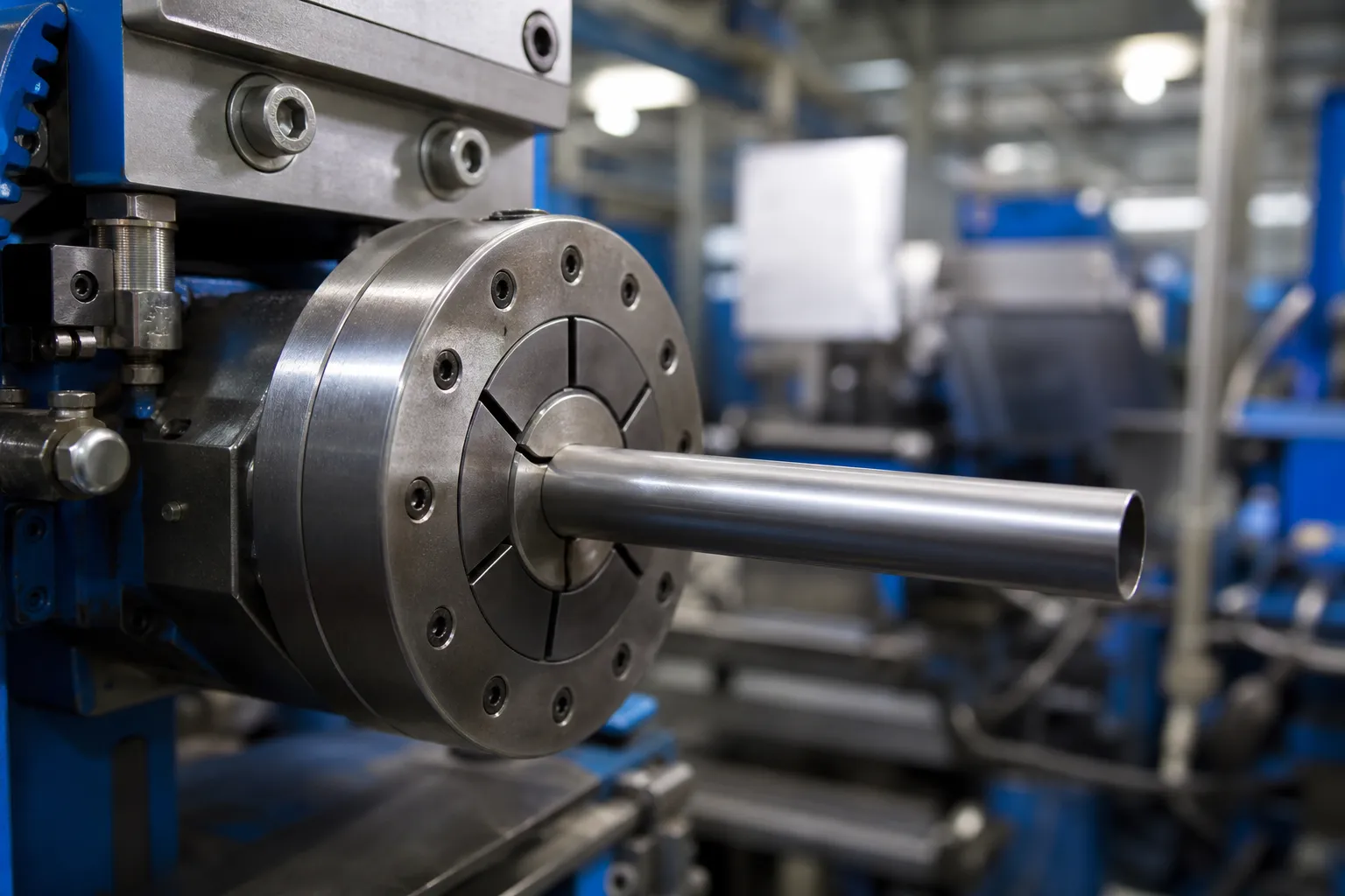
Correction Method and Protected Contact Map
The correction method is a wall-protective variant of îndreptare prin presare punctuală: the sleeve rotates on precision rollers or between centers on a mandrel arrangement, sensors map OD runout (and bore where specified), and a broad, shaped press shoe applies small incremental loads at the bow apex. The support span is kept short to prevent wall ovalizing between supports, and the press point never lands on vent holes, ports or thin sections. Roll geometry and contact stress limits follow the reasoning in surface-protection tooling in straightening.
Default no-press and no-support zones:
- the finished bore surface;
- vent holes, side-wall ports and relief features;
- flange-to-body transitions;
- nitrided or coated surfaces;
- any galled, scored or heat-discolored zone;
- direct clamping in a plain v-collet that would ovalize the wall.

Closed-Loop Process
- Identify the sleeve: part number, material, grosimea peretelui, etapă, rework history — and inspect the paired core pin.
- Clean and inspect: plictisit, DE, flange faces, vent features, galling, fisuri.
- Qualify the setup: shaped rollers/supports, low sensor force, verified no-wall-distortion loading.
- Map OD straightness by section plus wall thickness variation.
- Classify the deviation; route out-of-round and concentricity cases to regrind or disposition.
- Index the apex; apply small incremental loads with full-contact supports; opriți-vă pe rigiditate anormală.
- Eliberare completă, remeasure the complete map; iterate within the allowed count.
- Verify released straightness, wall roundness, concentricity and free slide on the actual core pin.
- Record maps, force curves and disposition for traceability.
Criterii de acceptare
- OD straightness (TIR) within the drawing specification, measured released and repeated;
- wall thickness variation within the drawing limit — proof that bore and OD remain concentric;
- bore and OD roundness unchanged by correction;
- no indentations, ovalizing marks or flange distortion;
- vent features intact;
- a functional slide check: free, smooth travel over the actual core pin through the full stroke, with the mold’s plate bores where available.
Common Pitfalls in Ejector Sleeve Straightening
- Using pin tooling on a tube. Narrow V-supports and a point load ovalize the wall locally: the runout map improves, the bore bind on the core pin gets worse. Sleeves need shaped full-contact supports and small load steps.
- Accepting on OD runout alone. The bore can be bent or bell-mouthed while the OD passes. Wall thickness variation around the circumference is the honest concentricity check.
- Straightening a sleeve with a bent core pin inside the story. The assembly binds again in hours. The sleeve, core pin and plate bores are one system and are inspected together.
- Pressing a drifting sleeve. If out-of-round and shape change keep returning, the cause is usually metallurgical (retained austenite) or thermal, not geometric. More pressing consumes the wall without stabilizing the part.
- Ignoring vent features in the contact map. A press shoe landing on a vent hole or port changes local stiffness and can close the feature that prevents vacuum lock at part release.
- Clamping in plain collets. Every clamping operation on a finished thin wall is a potential ovalizing event; soft-lined or shaped collets are the default, not an upgrade.
Date necesare pentru o propunere tehnică
- sleeve drawing and revision, with fit specifications for OD, bore and flange;
- gradul materialului, heat treatment specification and hardness;
- grosimea peretelui (minimum per side) and overall length;
- vent holes, ports and special features with locations;
- etapa procesului: post-heat-treatment, sol, or recovered from a mold;
- paired core pin specification and its measured condition;
- incoming geometry maps: OD runout by section, wall thickness variation, starea alezajului;
- zone de contact aprobate și interzise;
- remaining grind stock on OD and bore;
- straightness and concentricity acceptance values with measurement method;
- lot sizes and handling expectations;
- inspection and traceability requirements;
- representative samples for correction trials.
Întrebări frecvente
Can a bent ejector sleeve be straightened like an ejector pin?
Sometimes, but not with pin tooling. The solid pin process (see the ejector pin straightening solution) assumes a stiff section; a sleeve needs shaped full-contact supports, smaller load steps, and wall-roundness acceptance on both surfaces. Press a sleeve like a pin and you trade a visible bend for an invisible oval bore.
Why do sleeves go egg-shaped without any wear?
Trade literature attributes size and shape change in tool steel sleeves largely to retained austenite from heat treatment, in combination with machining and heat-treat sequencing. A sleeve that keeps drifting after correction is a material-process problem — stabilize the metallurgy first, or the straightening map will not hold.
When should a sleeve be replaced instead of straightened?
Replace when the wall is out of round beyond regrind stock, bore-to-OD concentricity cannot be restored within size limits, galling depth exceeds polish/regrind limits, the flange is distorted, or repeated corrections have already consumed the bend allowance of the wall.
Does straightening affect the vent hole function?
Vent holes and side-wall ports relieve vacuum and gas at part release. They are protected zones in the contact map precisely because local deformation around a port changes both the venting behavior and the local stiffness — correction must be planned away from them, and their condition is part of acceptance.
Build the Solution Around the Wall
An ejector sleeve is a thin-wall part whose straightness and roundness interact: correcting one can load the other, and the paired core pin defines the clearance both must respect. Wall integrity is the first acceptance gate – ovality or local denting from over-aggressive correction disqualifies the part regardless of the straightness reading. Related processes are collected in the mold and die straightening hub.
Send the sleeve drawing, material and heat-treatment specification, grosimea peretelui, etapa procesului, incoming geometry maps and the paired core pin data, plus representative samples. The correction envelope is set jointly by the wall limits and the sleeve-pin clearance.