
Small-diameter medical drill components are difficult to straighten because the measuring force, rozstaw podpór, clamping error and correction increment can be significant relative to the workpiece stiffness. A part may appear straight in one fixture and show different runout when referenced from its functional shank or final assembly datum.
This solution is based on a published source project that reports a Ø2 mm × 70 mm workpiece and a 0.05 mm straightness requirement. Those numbers are treated as customer inputs, not as proven production results. A guarantee requires the controlled drawing, fakt, metoda miernikowa, representative samples and before/after records.
Reported Project Inputs and Evidence Status
| Przedmiot | Published Input | Evidence Status |
|---|---|---|
| Przedmiot obrabiany | Small medical drill component | Real part and equipment photos available |
| Średnica | 2.0 mm | Reported in source article; drawing not attached |
| Długość | 70 mm | Reported in source article; drawing not attached |
| Cel | 0.05 mm prostoliniowość | Wymagania klienta zgodnie ze zgłoszeniem; raport wyników niedostępny |
| Tworzywo / twardość | Nie podano | Należy potwierdzić |
| Dane funkcjonalne | Nie podano | Należy określić na podstawie rysunku i użycia |
| Etap procesu | Nie podano | Zęby, obróbka cieplna, należy potwierdzić stan powłoki i końcowego szlifowania |
| Wynik produkcji | Uznane za osiągnięte | Nie jest używany jako fakt bez zapisów pomiarów i możliwości |

Dlaczego mała średnica zmienia pomiar
Na szczupłą część, sonda może odchylić przedmiot obrabiany, the supports can impose a shape and the part's own orientation can change the reading. Rozwiązanie musi definiować coś więcej niż tylko rozdzielczość czujnika.
A separate surgical-drill article notes that blank straightening is normally required before grinding, with runout held within about 0.1 mm at that stage. That value describes a common process-stage requirement rather than a universal tolerance; the stage and the tolerance must be confirmed from each drawing.
Dane funkcjonalne
MAE's official application guidance states that drills and deep-hole drills are straightened relative to the clamping shank. Ułatwia to użycie funkcjonalnie odpowiedniego trzpienia lub punktu odniesienia zamiast dowolnej wygodnej powierzchni cylindrycznej.
Siła sondy i geometria styku
Siła sondy, kształt trzpienia i miejsce styku muszą być niskie i wystarczająco stabilne, aby nie wygiąć ani nie pozostawić śladów na elemencie. System pomiarowy powinien wykazywać powtarzalność na części wzorcowej lub reprezentatywnej, zanim zostanie użyty do kontroli korekcji.
Rozstaw podpór
Podpory muszą stabilizować obrabiany przedmiot, nie powodując jego prostowania. Ich pozycje, promienie i materiał kontaktowy stają się częścią kontrolowanej receptury.
Prostoliniowość a bicie
Oryginał 0.05 mm stwierdzenie nazywa charakterystyczną prostolinijnością, ale maszyna wirująca może w rzeczywistości zgłaszać bicie promieniowe lub TIR. Rysunek musi rozwiązać tę różnicę, zanim zostanie złożona obietnica liczbowa.
Automatyczna obsługa małych części
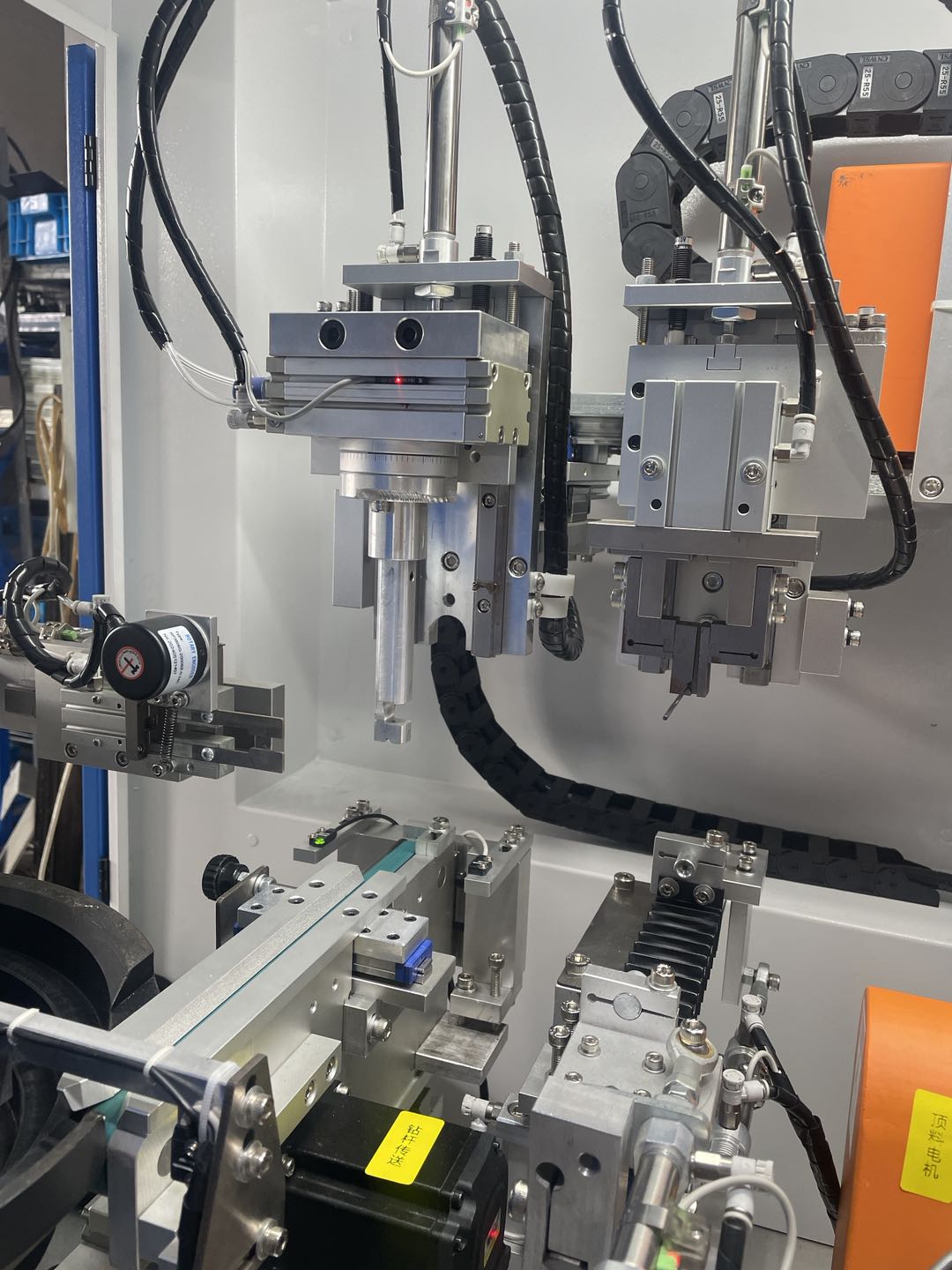
The source photos show a compact machine with a bowl feeder, transfer mechanism and dedicated measurement/correction tooling. These images confirm that automated separation and loading were developed for a small component family; they do not prove an output rate or unattended production period.

Handling design must be verified for:
- part orientation and end-feature recognition;
- tangling or overlap risk;
- contact with finished or critical surfaces;
- transfer repeatability into the measuring datum;
- mixed-part prevention and recipe control;
- reject containment and line clearance.
Zalecany proces w pętli zamkniętej
1. Identify and orient
The feeder separates the workpieces and presents the correct end and orientation. Presence and seating checks prevent a cycle with a missing or doubled part.
2. Ustal bazę funkcjonalną
Obrabiany przedmiot znajduje się na zatwierdzonym chwycie, centra lub odniesienia zdefiniowane na rysunku. Siła zaciskania jest ograniczona, aby uniknąć fałszywego zagięcia.
3. Zmierz stan wejściowy
Część obraca się lub indeksuje, podczas gdy sondy o małej sile odczytują zatwierdzone pozycje. System rejestruje stan początkowy i potwierdza, że sygnał mieści się w zatwierdzonym zakresie.
4. Zastosuj mikrokorektę
Narzędzie prasujące stosuje kontrolowane, ograniczone przemieszczenie w zatwierdzonej strefie gładkiej. Preferowane są małe korekty i ograniczenia siły/skoku niż duży pojedynczy ruch.
5. Zmierz ponownie
Bezpośrednio po korekcie stosowana jest ta sama metoda odniesienia i sondy. Jeśli wynik pozostaje poza celem, kolejna korekta jest dozwolona tylko w ramach zatwierdzonego limitu iteracji.
6. Dyspozycja i zapis
Część została przyjęta, odrzucone lub przekazane do przeglądu zgodnie z regułą dotyczącą konkretnego rysunku. Wymagane dane można przechowywać lub eksportować, jeśli są uwzględnione w zatwierdzonym zakresie projektu.
Powiązany film dotyczący prostowania wierteł medycznych
Poniższy film na kanale Maszyna do prostowania jest zatytułowany „Jak wyprostować wiertło za pomocą maszyny do prostowania” i opisuje dostosowaną do indywidualnych potrzeb wiertarkę medyczną. Pokazuje automatyczną komórkę do prostowania wierteł medycznych. The video description's customer location and labor-saving statement are not used as verified project results.
Weryfikacja 0.05 mm Cel
Zgłoszone 0.05 wymaganie mm jest technicznie niekompletne do czasu określenia charakterystyki i punktu odniesienia.
| Element walidacyjny | Wymagana definicja |
|---|---|
| Charakterystyczny | Prostota, bicie promieniowe, TIR lub współosiowość |
| Fakt | Funkcjonalny trzonek, centra, czasopisma lub dedykowany miernik |
| Pomiar pozycji | Dokładne lokalizacje osiowe i powierzchnie |
| Miernik | Rezolucja, siła sondy, stan mocowania i kalibracji |
| Korelacja | Umowa między kontrolą końcową maszyny a klientem |
| Przychodzące okno | Maksymalne zgięcie i dopuszczalny kształt przed prostowaniem |
| Akceptacja powierzchni | Dozwolone znaki, zadziory i strefy krytyczne |
| Dowody zdolności | Wielkość próby i kryterium statystyczne wymagane przez klienta |
Prawidłowe oświadczenie publiczne brzmi: projekt źródłowy zgłosił a 0.05 cel mm; osiągnięcie pozostaje niezweryfikowane do czasu dostarczenia powiązanych zapisów.
Interfejs systemu jakości medycznej
Rozporządzenie dotyczące systemu zarządzania jakością FDA weszło w życie w lutym 2, 2026 i zawiera ISO 13485:2016 do USA. struktura. Legalny producent pozostaje odpowiedzialny za określenie mających zastosowanie wymagań i zatwierdzenie procesu produkcyjnego w swoim systemie jakości.
Komora prostująca może obsługiwać kontrolowane zapisy, takie jak identyfikator części/partii, rysunek i rewizja przepisu, pomiar wejściowy/końcowy, liczba poprawek, alarm history and disposition. Record retention, electronic controls, access, audit trail and interface validation must be specified by the customer; the machine does not independently certify FDA or ISO compliance.
Przykładowy test i plan akceptacji
- supply representative samples across multiple incoming-bend conditions;
- identify material, twardość, heat-treatment and surface state;
- freeze datum, obsługuje, probe force and correction contact zones;
- run repeat measurement before correction to quantify measurement variation;
- record every before/after result and rejected attempt;
- compare machine readings with the customer's final gauge;
- inspect functional surfaces for defined marks or damage;
- test automatic orientation, transfer and mixed-part controls;
- approve only the demonstrated workpiece and incoming-condition window.
Related Pages and Equipment
Zobacz Rozwiązania do prostowania urządzeń medycznych, Aplikacja do prostowania wierteł medycznych I Ortopedyczna maszyna do prostowania wierteł chirurgicznych ZD300. Dane katalogowe stanowią wstępną informację dotyczącą wyboru i należy je uzgodnić z wynikami próbek i ostateczną wyceną.
Czego to rozwiązanie nie obiecuje bez dowodów
- że pokazana część jest gotowym lub zatwierdzonym wyrobem medycznym;
- że każde Ø2 × 70 mm część wykorzystuje ten sam materiał lub punkt odniesienia;
- stabilny 0.05 mm produkcji bez określonej grubości i badania zdolności;
- czas jednego cyklu, poprawę wydajności lub oszczędność pracy;
- zerowych śladów lub uszkodzeń bez specyfikacji kontroli;
- że jeden podajnik/zestaw narzędzi obejmuje wiele rodzin części;
- automatyczne FDA lub ISO 13485 zgodność.
Informacje do wysłania w celu złożenia wniosku
Wyślij kontrolowany rysunek, tożsamość przedmiotu obrabianego i etap procesu, reprezentatywne próbki, materiał i twardość, rozkład zagięć przychodzących, ostateczna charakterystyka i punkt odniesienia, metoda miernikowa, dozwolone strefy kontaktu, wymagania dotyczące powierzchni/czystości, wymagania dotyczące docelowej wydajności i dokumentacji produkcyjnej.
Skontaktuj się z StraighteningTech w celu zorganizowania badania wykonalności na próbie i badania korelacji pomiarów.
Często zadawane pytania
Jest 0.05 mm gwarantowana prostoliniowość dla tego przedmiotu obrabianego?
Nie tylko z opublikowanego artykułu. Jest to zgłoszony wymóg. Gwarancja wymaga rysunku, fakt, korelacja wskaźników i reprezentatywne wyniki próbek.
Dlaczego siła sondy jest ważna dla a 2 część mm?
Ponieważ sonda i uchwyt mogą odchylić smukły element i zmienić pozorny odczyt. W ramach metody pomiaru należy sprawdzić siłę sondy i rozmieszczenie podpór.
Czy podajnik obsługuje kilka rozmiarów?
Potencjalnie z częściami do wymiany, ale orientacja, zachodzić na siebie, Dla każdej rodziny należy przetestować kontakt powierzchniowy i transfer. Sam przepis na oprogramowanie nie wystarczy.
Czy ta strona może wykorzystywać ten sam proces, co zębate wiertło medyczne??
Logika zamkniętej pętli jest podobna, ale ryzyko związane z pomiarem i oprzyrządowaniem jest różne. Część zębata/nieokrągła wymaga pomiaru uwzględniającego profil, podczas gdy mała, gładka lub schodkowa część jest zdominowana przez pomiar i obsługę przy małej sile.
Czy maszyna sprawia, że proces jest zgodny z FDA?
NIE. Może wspierać kontrolowane, zatwierdzony proces i wymagane zapisy. The legal manufacturer owns regulatory applicability and quality-system compliance.
Techniczna granica odniesienia
- Wskazówki MAE dotyczące przedmiotu obrabianego dla wierteł i odniesienia do chwytu mocującego: https://mae-group.com/en/aplikacje-przedmiotów/
- Rozporządzenie dotyczące systemu zarządzania jakością FDA: https://www.fda.gov/medical-devices/postmarket-requirements-devices/quality-management-system-regulation-qmsr
These sources establish engineering and quality-system principles. They do not prove the reported 0.05 mm project result.