
En jernbaneaksel er en sikkerhetskritisk smidd komponent med store seksjonsendringer, hjulseter, lagerjournaler, skuldre, fileter og valgfrie gir- eller bremseskiveseter. Retteoppgaven kan skje mens smiingen fortsatt er varm, etter varmebehandling, under grovbearbeiding eller etter at funksjonelle overflater er ferdigbehandlet. Hvert trinn skaper en annen kombinasjon av datumkvalitet, materiell respons, overflaterisiko og inspeksjonsansvar.
En pålitelig løsning for jernbaneakselretting begynner derfor med prosessstadiet i stedet for en pressetonnasje. Prosjektet skal definere akselfamilien, temperaturtilstand, tillatte korreksjonssoner, håndtering av tunge deler, målereferanse, godkjenning av frigjorte deler og grensen mellom akselretting og senere hjulsettmontering.
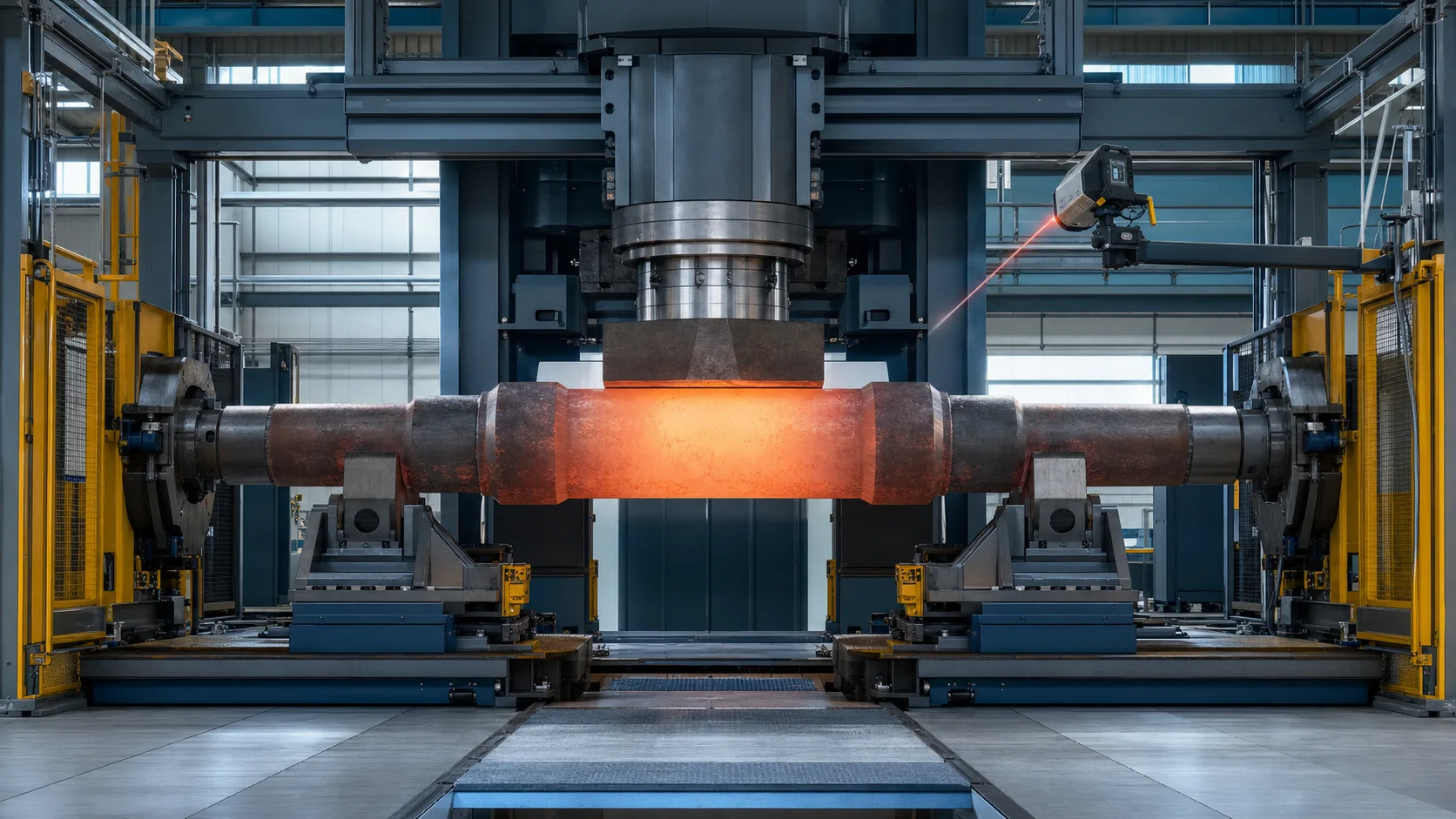
Dette er en ingeniørkonseptillustrasjon, ikke et fotografi på kundesiden. Faktisk akselgeometri, temperaturvindu, pressekapasitet, håndtering av layout og verktøy krever tegninger og representative prøvetester.
Jernbaneakselretting presser ikke hjulsett
Begrepene aksel, akselaksel og hjulsett blandes ofte i tidlige henvendelser, men de beskriver ulike arbeidsstykker og prosesser.
| Arbeidsstykke eller prosess | Hovedoppgave | Utrettingsomfang |
|---|---|---|
| Bar jernbaneaksel | Riktig bøy- eller akseforhold før hjulmontering | Denne siden |
| Sammensatt hjulsett | Hjul, bremseskiver, gir eller lagre er allerede montert | Krever en separat montering-stat risiko og datum gjennomgang |
| Hjulsett presser | Sett sammen eller fjern hjul, skiver og gir med kontrollert interferens og kraft-avstandsregistrering | Ikke en retteprosess |
| Bilakselaksel | Mindre kjøretøys drivlinjekomponent med splines, flenser eller girfunksjoner | Dekket av de dedikerte Rettingsløsning for bilakselaksel |
| Hjulsettbalansering eller kjøretest | Evaluer massefordeling eller funksjonell oppførsel til det sammensatte roterende systemet | Ikke erstattet av akselretting |
MAE skiller hjulsettaksler under støpte/smidde deler fra hjulsettpresser som brukes til montering. Det skillet er viktig: en maskin konstruert for å korrigere en bar smiing er ikke automatisk kvalifisert til å presse hjul eller korrigere et sammensatt hjulsett.
Definer jernbaneakselfamilien
Tilbudet skal identifisere hele delfamilien, ikke bare maksimal lengde og diameter. Relevante varianter inkluderer:
- drevne eller ikke-drevne aksler;
- solide aksler og aksler med delvis eller full langsgående boring;
- indre lager og ytre lager layouter;
- enkle fraktaksler og flerseter høyhastighetsaksler;
- hjulseter pluss utstyr, bremseskive eller andre funksjonelle seter;
- grov smiding med uregelmessige ender og maskinerte aksler med ferdige senterhull;
- belagt, valsede eller induksjonsherdede varianter;
- forskjellige stålkvaliteter, varmebehandlingsruter og hardhetsforhold;
- nyproduksjonsaksler kontra vedlikeholdsdeler, når korrigering er tillatt i henhold til gjeldende spesifikasjon.
GHH-BONATRANS lister solid, hul, drevet, ikke-drevet, indre lager, flersete, belagte og induksjonsherdede akselfamilier. Disse variasjonene endrer stivhet, sikre kontaktflater, signaltolkning og tillatt korreksjonskonvolutt. De kan ikke representeres av en universell oppskrift.
Frys produksjonsfasen før du velger utstyr
Etter smiing, Før du snur
Akselen kan ha skala, uregelmessige ender, høy temperatur og ufullstendige datumflater. Galdabini beskriver automatisk jernbaneakselretting rett etter smiing og før vending, med manipulatorer for uregelmessige ender, beskyttelse mot høye temperaturer, temperaturmåling og beskyttelse mot kalk. På dette stadiet, løsningen er en varmsmiingsprosesscelle, ikke en presis sluttinspeksjonsmaskin.
Etter varmebehandling
Varmebehandling kan introdusere eller omfordele bøyning og gjenværende stress. Akselen er kjøligere og mer dimensjonsdefinert, men materiell styrke, hardhet, overflatetilstand og rissrisiko må være kjent før korrigering. En senere maskineringsgodtgjørelse kan fortsatt eksistere.
Etter grovbearbeiding
Sentrale hull, journaler og setespor kan nå gi mer stabile målereferanser. Gjenværende lager kan beskytte endelige overflater, mens prosjektet kan korrelere akselkroppen til den fremtidige funksjonsaksen før ferdig bearbeiding.
Etter ferdig bearbeiding
Bærende journaler, hjulseter, fileter og senterhull er ferdige funksjonelle funksjoner. Verktøykontakt, innrykk, riper og lokalt stress blir kritisk. Korrigeringsgrenser krever normalt strengere kontroll og en godkjent inspeksjonsrute etter retting.
Etter belegg, Overflatevalsing eller lokal herding
Korrigeringsruten må respektere overflatebehandlingsspesifikasjonen. Retting kan ikke antas trygt etter belegg, forsterkende valsing eller induksjonsherding uten material- og prosessgodkjenning.
| Scene | Typisk datotilgjengelighet | Hovedprosessrisiko | Nødvendig prosjektbeslutning |
|---|---|---|---|
| Varm smiing | Uregelmessig kropp og ender | Temperaturvariasjon, skala, håndtering og begrenset presisjonsdatum | Temperaturvindu, hot-contact verktøy og nedstrøms maskineringsgodtgjørelse |
| Varmebehandlet blank | Mer stabil kropp, uferdige funksjoner | Høyere styrke, restspenning og sprekkrisiko | Materialkonvolutt, inspeksjon og tillatt plastbelastning |
| Grovbearbeidet | Sentre og sylindriske spor kan eksistere | Prosesslager kan skjule endelig funksjonell oppførsel | Referanseakse, lagergodtgjørelse og neste maskineringsoperasjon |
| Bearbeidet ferdig | Funksjonelle journaler og plasser tilgjengelig | Overflateskader, lokal yield og datum over-begrensning | Beskyttede kontakter, sluttmåling og NDT/overflatekontroller |
Varm retting vs kald retting
Varme- og kaldekorreksjon er ikke utskiftbare driftsmoduser som kun velges for enkelhets skyld.
| Beslutningsfaktor | Varm retting | Kald retting |
|---|---|---|
| Typisk stilling | Umiddelbart etter smiing, før du snur | Etter avkjøling, varmebehandling eller maskinering |
| Arbeidsstykkets tilstand | Skalert, termisk ekspanderende, muligens uregelmessig i endene | Dimensjonsmessig mer stabil med tydeligere sylindriske trekk |
| Materiell respons | Bruker forhøyet temperaturplastisitet innenfor et godkjent prosessvindu | Krever en validert styrke, forskyvning og tilbakefjæring |
| Måleprioritet | Temperatur, brutto geometri og nedstrøms lagertillegg | Frigitt akse, runout/koaksialitetsforhold og funksjonelle datum |
| Verktøy prioritet | Varmebestandighet, skalatoleranse og robuste manipulatorer | Overflatebeskyttelse, radiused kontakter og datum repeterbarhet |
| Akseptgrense | Mellomsmiing geometri; senere operasjoner må måles på nytt | Kan nærme seg endelig aksept, avhengig av prosessstadiet |
Galdabini opplyser at varmretting kan bruke materialplastisitet etter smiing. Dette støtter prosesskonseptet, men det definerer ikke en universell temperatur eller kraft. Det akseptable vinduet må komme fra akselmaterialet, smiing og varmebehandlingsvei, metallurgisk godkjenning og representative forsøk.
Definer hva "rett" betyr på tegningen
Én utløpsverdi kan ikke beskrive hele akselen. De kontrollerte egenskapene kan omfatte:
- rettheten til en spesifisert sylindrisk overflate eller avledet medianlinje;
- radiell utløp av lagertappene, hjulseter, girseter eller bremseskiveseter;
- koaksialitet eller akseforhold mellom adskilte funksjonsseter;
- forhold til senterhull eller en annen produksjonsakse;
- rundhet og sylindrisitet til individuelle seter;
- skulderstilling, ansiktsutløp og overgangsgeometri;
- lengdeboringsposisjon eller veggfordeling der det er aktuelt;
- overflatetilstand, hardhet og tillatte restspenningskriterier;
- magnetisk partikkel, ultralyd eller andre inspeksjonskrav;
- hjulsett-nivå geometri etter montering, som forblir en egen sjekk.
For et klart skille mellom form, akse- og rotasjonsindikasjoner, bruk Skaftretthet vs Runout vs TIR-guide. Jernbaneakseltegningen og gjeldende jernbanespesifikasjon forblir akseptmyndighet.
Etabler et datumhierarki
Løsningen bør skille minst fem referanser:
- tegne datums som definerer toleransen;
- senterhull eller prosesssentre som brukes ved maskinering;
- fysiske støtter og rotasjonsanordninger som brukes av rettemaskinen;
- sensorspor som brukes til å rekonstruere den målte aksen;
- kundemåleren eller hjulsettets referanse som brukes for endelig korrelasjon.
Disse referansene kan ha sammenheng, men de er ikke automatisk likeverdige. En stabil støtteflate kan gjøre målingen repeterbar mens den fortsatt er irrelevant for den funksjonelle hjulseteaksen. Omvendt, senterhull kan være nyttige produksjonsreferanser, men kan være skadet, uferdige eller ikke utpekt som endelige datum.
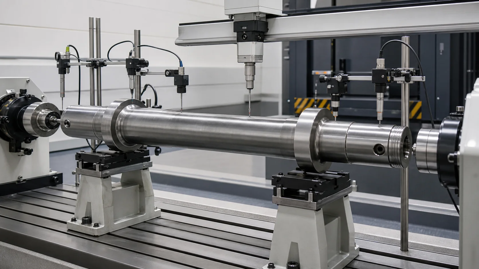
Denne ingeniørkonseptillustrasjonen viser flere målespor på en bar aksel. Den foreskriver ikke antall sensorer, kontaktmetode eller datumvalg for hver aksel.
| Målespor | Mulig utgang | Hovedfortolkningsrisiko |
|---|---|---|
| Akselkropp | Global bøyekurve | Skala, avsmalning eller lagervariasjon kan fremstå som bøy |
| Bærende journaler | Journalutløp og akseforhold | En lokal formfeil kan forvrenge et enkelt-proberesultat |
| Hjulseter | Hjul-sete akse og utløp | Ferdige overflater trenger beskyttet kontakt eller berøringsfri sensing |
| Gir- eller bremseskiveseter | Ekstra funksjonell akseforhold | Antall funksjoner og avbrudd trenger riktig maskering |
| Sentrale hull | Maskinering-akse korrelasjon | Sentertilstand representerer kanskje ikke tegningsdatumet |
| Langsgående boring | Bore-til-ytre-akse forhold | Krever en egen intern måle- eller inspeksjonsmetode |
De Veiledning for valg av trinn for akselmåling forklarer hvordan man tegner datum, maskinstøtter og sensorspor bør skilles før du programmerer en oppskrift.
Mål den frigjorte akselen, Ikke bare den belastede formen
En tung aksel bøyer seg under sin egen masse, støttereaksjoner og målekraft. Den observerte kurven endres med støtteavstand, rotasjonsvinkel og temperatur. En lastet presseavlesning kan derfor ikke bevise den endelige frigitte geometrien.
Måleplanen bør definere:
- støttekoordinater, kontaktbredde og høyde;
- akselorientering og rotasjonssekvens;
- temperaturtilstand og stabiliseringsregel;
- sagbehandling eller kundekorrelasjonsmetode;
- sensorkraft, spekter, oppløsning og funksjonsmasker;
- antall og plassering av aksialstasjoner;
- evaluering av flere vinkelposisjoner;
- måling av frigitt tilstand etter hver korreksjon;
- sluttmåler eller uavhengig inspeksjonskorrelasjon.
Kontrollen skal skille lokal rundhet eller overflatesignal fra global bøy. Noe annet, den kan bruke en kraftig korreksjon som svar på en lokal funksjon som retting ikke kan reparere.
Bygg et trygt presse- og støttekart
Akseltegningen bør konverteres til maskinkoordinater med godkjent, begrensede og forbudte kontaktområder.
Typiske beskyttede soner
- lagertapper og tetningsflater;
- hjulsetekanter og ferdige interferensflater;
- gir og bremseskive seter;
- fileter, skuldre og seksjonsoverganger;
- senterhull og gjengede endefunksjoner;
- oljehull, borer, belegg og identifikasjonsmerker;
- lokalt herdede eller styrkevalsede regioner med mindre godkjent;
- kjente indikasjoner eller feilplasseringer.
Verktøyprinsipper
- bruk sko med bred radius og saler tilpasset godkjent diameter;
- hindre kantbelastning ved skuldre eller avsmalninger;
- tillate kontrollert langsgående bevegelse der bøyemetoden krever det;
- hold kontakttrykket innenfor den validerte overflategrensen;
- overvåke kraft og forskyvning i stedet for å stole på ramposisjon alene;
- forhindre valg av resept når akselfamilien eller orienteringen er feil;
- inspiser verktøyets renslighet og innebygd vekt før hver batch.
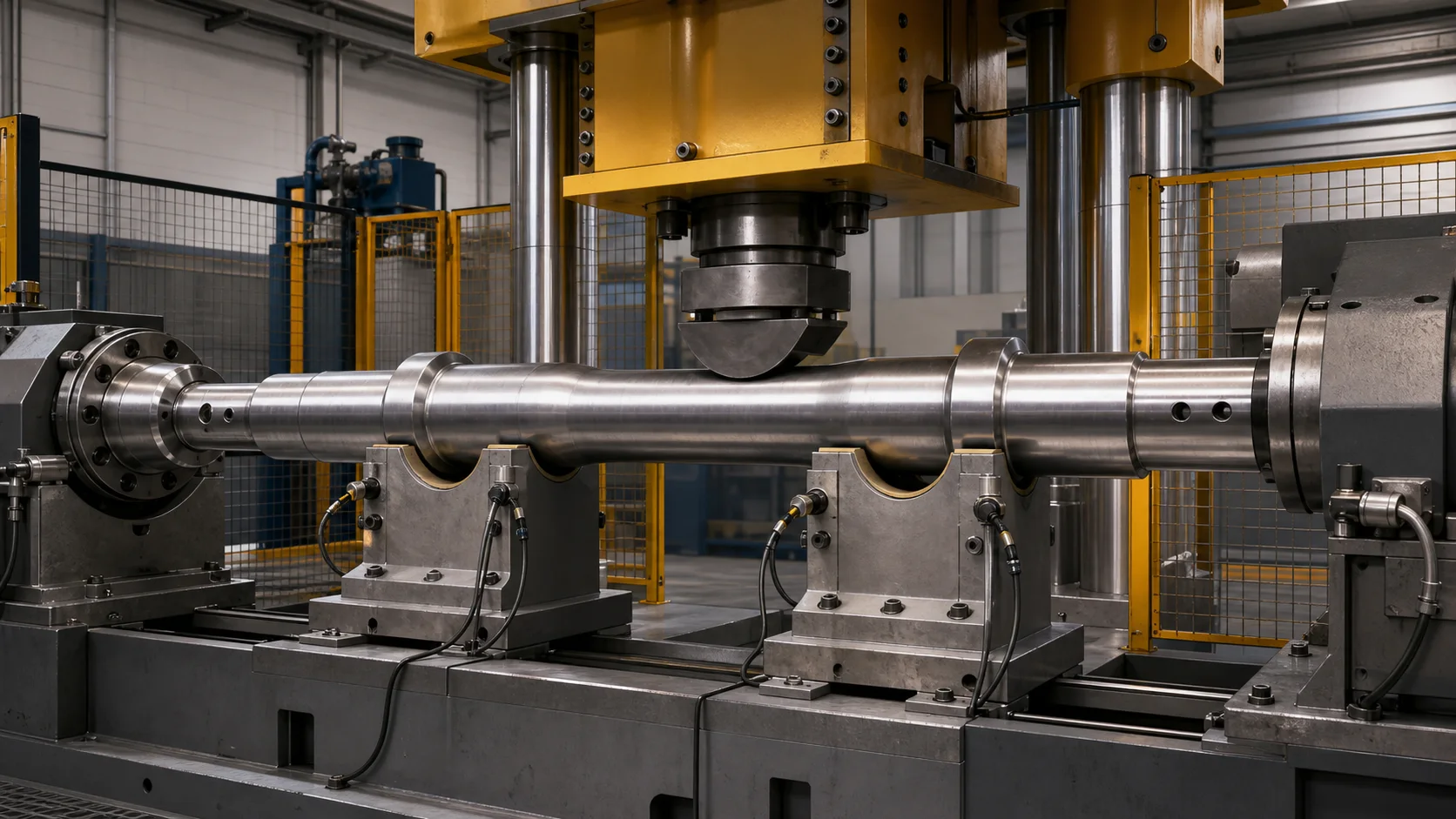
Denne konseptillustrasjonen viser korreksjon på godkjente sylindriske soner. Det faktiske antallet støtter, span, skoradius, kraftgrense og tillatt korreksjonsretning må fastsettes ved prøvetesting.
Temperatur, Skala og termisk ekspansjon
Temperatur er ikke bare et problem med maskinbeskyttelse. Det påvirker dimensjonen, materiell respons, friksjon, sensoradferd og betydningen av et målt avvik.
For en varm prosess, cellen skal definere:
- innkommende og minimum korreksjonstemperatur;
- hvor og hvordan temperaturen måles;
- tillatt temperaturvariasjon langs og rundt akselen;
- korrigeringsavskjæring og disposisjon når akselen avkjøles utenfor vinduet;
- kalkfjerning eller toleranse for kalk under støtter og verktøy;
- varmeskjold for sensorer, kabler, vakter og operatører;
- beskyttelse og oppsamling for fallende skala;
- overføringstid mellom smiing, mål, korrigering og nedstrømsoperasjoner.
For en kald eller ferdigbearbeidet prosess, løsningen bør definere målestabilisering og forhindre at varme deler aksepteres mot en kald master uten korrelasjon.
Håndtering av tunge deler er en del av prosessen
Jernbaneaksler kan ikke behandles som vanlige håndlastede aksler. Laster, rotasjon, oversettelse og lossing påvirker sikkerheten, overflatetilstand og datum repeterbarhet.
Galdabini beskriver spesifikke manipulatorer for uregelmessige smidde ender og valgfrie kjede-/gaffellastesystemer. MAE identifiserer også hjulsettaksler som smidde deler som håndteres i krevende miljøer. Overførbare prosjektkrav inkluderer:
- delidentifikasjon før lasting;
- løfte- og støttepunkter godkjent for hver akselvariant;
- synkroniserte manipulatorer eller transportører dimensjonert for den virkelige massen og tyngdepunktet;
- kontrollert rotasjon uten å dra ferdige seter;
- positiv deteksjon av sittende og fastklemte tilstander;
- utelukkelsessoner for lagret energi og fare for tapte deler;
- skala, olje- og sponhåndtering;
- gjenopprettingslogikk for strømtap, sensorfeil eller avbrutt korrigering;
- sikker fjerning av deler som ikke samsvarer.
Håndteringstid og akseltemperaturtap må vurderes sammen for en varm linje. En mekanisk kapabel presse kan fortsatt mislykkes i prosessen hvis overføring og indeksering lar smiingen forlate sitt godkjente temperaturvindu.
Bruk en lukket sløyfe-rettingssekvens
1. Identifiser akselen
Last inn den validerte oppskriften fra delenummeret, tegningsrevisjon, prosessstadiet, materiale/varmebehandlingstilstand og akselfamilie.
2. Bekreft forutsetning
Bekreft temperaturen, overflatetilstand, skalanivå, funksjonsfullføring, orientering og at akselen har passert alle nødvendige oppstrøms porter.
3. Last på godkjente soner
Bruk de definerte løfte- og støttepunktene. Bekreft sitteplasser og forhindre at ferdige overflater glir over forurenset verktøy.
4. Mål den opprinnelige geometrien
Roter eller skann akselen i henhold til oppskriften. Rekonstruer den aktuelle kroppen eller funksjonsaksen og maskeoverganger, hull og uregelmessige funksjoner.
5. Separer korrigerbar bøyning fra andre feil
Avvis eller rute separat når signalet indikerer lokal formfeil, skadede sentre, overflatedefekter, feil maskineringslager, overdreven ovalitet eller et ikke-korrigerbart trekkforhold.
6. Velg en sikker korrigeringsposisjon
Velg støttespenn, korrigeringsretning og trykksone fra godkjent kart. Påfør temperatur, makt, forskyvnings- og korrigeringsgrenser.
7. Påfør kontrollert overbøyning
Bruk den validerte modellen for materialrespons og tilbakespring. Registrer kraft og forskyvning gjennom hele slaget og stopp ved enhver unormal signatur.
8. Fullstendig slipp og mål på nytt
Fjern korrigeringsbelastningen før du bedømmer resultatet. Kontroller hvert kontrollerte spor på nytt fordi en korreksjon kan endre en annen stasjons- eller akseforhold.
9. Inspiser akselen
Utfør den nødvendige overflaten, dimensjonale og ikke-destruktive kontroller i henhold til akseltegningen, prosessspesifikasjon og korreksjonshistorikk.
10. Ta opp og avlast
Lagre akselidentiteten, revisjon av oppskriften, temperatur, før/etter kart, korrigeringskoordinater, kraft-forskyvningskurver, alarmer og endelig disponering når sporbarhet er påkrevd.
Definer automatisk, Semi-automatisk og manuell omfang
| Modus | Passer når | Nødvendige kontroller |
|---|---|---|
| Automatisk | Stabile akselfamilier, repeterbar oppstrømstilstand og definert produksjonsflyt | Del-ID, automatisert måling, oppskriftskontrollert verktøy, korrigeringsgrenser og sporbarhet |
| Halvautomatisk | Flere varianter eller operatørassistert håndtering med repeterbar måling | Veiledet oppsett, forriglinger, oppskriftstillatelser og uavhengig utgivelsesmåling |
| Manuell trykk | Utvikling, reparasjon eller lavvolumsarbeid der det er tillatt | Kvalifisert operatør, kontrollert måler, kraft/fortrengningsindikasjon og dokumenterte vedtaksregler |
Automatisering fjerner ikke behovet for metallurgiske grenser og prøvevalidering. Den gjør bare en validert beslutningsrute repeterbar.
Hold retting og inspeksjonsansvar atskilt
Retting endrer global geometri. Den reparerer ikke alle akselfeil.
| Betingelse | Retting kan potensielt adressere | Separat inspeksjon eller prosess påkrevd |
|---|---|---|
| Global bøyning | Ja, innenfor den validerte material- og geometrikonvolutten | Frigitt måling og endelig korrelasjon |
| Journal eller sete lokal skjemafeil | Vanligvis nei | Avgjørelse om maskinering eller avvisning |
| Crack, runde eller skadelig indikasjon | Ingen | Godkjent NDT og disponeringsprosedyre |
| Langsgående boringsdefekt eller posisjon | Ikke ved ekstern bøykorreksjon alene | Intern måling/NDT og ingeniørgjennomgang |
| Overflateskader eller beleggsfeil | Ingen | Overflatereparasjon eller avvisningsrute |
| Feil hjulinterferenstilpasning | Ingen | Hjulsett engineering og monteringsprosess |
| Hjulsett ubalanse | Ingen | Avbalansering eller funksjonstest etter montering |
Lucchini RS presenterer inspeksjon som et tydelig trinn i sin integrerte akselproduksjonsrute. GHH-BONATRANS fremhever også langsgående boringer som muliggjør ikke-destruktiv diagnostikk. Rettecellen skal utveksle sporbarhetsdata med kvalitetsoperasjoner, men det bør ikke innebære at et rett geometriresultat erstatter nødvendig inspeksjon.
Foreslått Rettecelle for jernbaneaksel
En prosjektspesifikk celle kan inkludere:
- bevoktet kraftig presse eller bevegelig portal størrelse fra prøvestyrkedata;
- justerbare brede støtter og utskiftbare sko med radius;
- manipulatorer for uregelmessig smiing eller beskyttet rotasjon av maskinerte aksler;
- temperaturmåling og varme/kalkbeskyttelse for varmbehandling;
- kontakt- eller berøringsfri geometrisensorer valgt for den faktiske overflatetilstanden;
- delidentifikasjon og oppskriftshåndtering;
- makt, forskyvning og temperaturinnsamling;
- full utløsning og automatisk ommåling;
- transportører, kjeder, gafler eller løftegrensesnitt tilpasset planteflyten;
- avvis ruting og sikker gjenopprettingssekvens;
- sporbarhetsgrensesnitt for MES eller kvalitetsposter der det er nødvendig.
Den endelige arkitekturen avhenger av om målet er en varm smilinje, en korrigeringsstasjon for ettervarmebehandling eller en presisjonsbearbeidet akselcelle.
Prøveprøve og akseptplan
Ikke velg maskinen fra en nominell akseldiameter alene. En representativ prøvematrise bør dekke:
- minste og største akselseksjoner;
- solide og hule varianter der det er aktuelt;
- minimum og maksimum lengde og masse;
- materialkvaliteter og varmebehandlingstilstander;
- forventet innkommende bøy størrelse og retning;
- temperaturområde for varm prosess eller kald stabiliseringstilstand;
- uregelmessige smiende ender og alle funksjonelle seteoppsett;
- representative overflate- og skalaforhold;
- godkjente og forbudte korreksjonsregioner;
- kundemåler eller uavhengig inspeksjonskorrelasjon;
- maksimalt antall korreksjoner og avvisningsregler.
Bruk Retting prøvetest og akseptveiledning å skille gjennomførbarhetsbevis, FETT, SAT og produksjonsevne. Registrer faktiske resultater i stedet for å konvertere en konkurrents maskinvurdering til et løfte for hele nettstedet.
Data som kreves for et teknisk forslag
Vennligst oppgi:
- akseltegninger og revisjoner;
- alle akselvarianter og års-/batchvolum;
- prosessstadiet ved retting;
- materiale, varmebehandling, hardhet og overflatebehandlingsdetaljer;
- varmprosesstemperaturvindu der det er aktuelt;
- innkommende bendfordeling, ikke bare den verste prøven;
- kontrollerte egenskaper, datum og akseptgrenser;
- tillatt støtte, klem- og trykksoner;
- forbudte soner, belegg, fileter, boringer og herdede områder;
- del masse, tyngdepunkt og plantehåndteringsbegrensninger;
- nødvendig NDT, grenser for overflateinspeksjon og korreksjon;
- kundemåler, inspeksjonsmetode og korrelasjonsprøver;
- sporbarhet, MES og rapportkrav;
- representative gode og avvikende prøver for forsøk.
Hvis disse inngangene er ufullstendige, den ansvarlige produksjonen er et konsept og testplan, ikke en ukvalifisert nøyaktighet eller syklustidsgaranti.
Ofte stilte spørsmål
Kan én maskin rette både varmsmiing og ferdige aksler?
Bare etter en full dual-prosess gjennomgang. Varmebeskyttelse, skala, manipulatorer, sensormetode, overflatebeskyttelse, datumkvalitet og akseptlogikk er fundamentalt forskjellige. En delt presseramme gjør ikke i seg selv begge prosessene kvalifiserte.
Skal akselen måles fra senter eller journaler?
Bruk det tegningsdefinerte funksjonskravet og godkjent prosessdatum. Sentre kan være nyttige for maskinering av korrelasjon, mens tappene eller hjulsetene kan representere monteringsfunksjonen bedre. Prosjektet bør måle nok funksjoner til å bevise forholdet deres i stedet for å anta at de er identiske.
Kan et sammensatt hjulsett korrigeres i samme celle?
Ikke uten en egen ingeniørvurdering. Monterte hjul, skiver og gir skifter masse, støttepunkter, stivhet, tilgjengelige pressesoner og inspeksjonskrav. Hjulsettpressing og balansering forblir separate operasjoner.
Betyr passerende utløp at akselen er trygg?
Ingen. Runout er ett geometrisk resultat. Materialtilstand, overflateintegritet, NDT, hardhet, prosesshistorikk og alle gjeldende jernbanekrav forblir uavhengige akseptporter.
Kan du garantere nøyaktighet fra tegningen alene?
Ingen ansvarlig leverandør bør gjøre det. Tegninger definerer målet, men representative utvalg etablerer kraft, tilbakespring, støtte innflytelse, temperaturoppførsel, overflaterisiko, repeterbarhet og målekorrelasjon.
Bygg løsningen rundt den virkelige akselprosessen
Vi utvikler jernbaneakselrettingsløsninger rundt selve smi- eller maskineringsstadiet, temperaturtilstand, aksel familie, funksjonelle datum, sikker lastbane og akseptmetode. Resultatet kan være en varm portalcelle, en kald kraftig automatisk maskin eller en kontrollert halvautomatisk presse - men utvalget følger bevis fra tegninger og prøveforsøk.
If this is your first railway axle straightening line, read the valgguide for aksel, rør- og profilarbeid first, then benchmark your budget against the FAT checklist for straightening machines.
Send akseltegningen, prosessvei, materiell tilstand, innkommende bøyedata, temperaturvindu og inspeksjonsmetode. Vi kan deretter definere målestrategien, verktøy kart, håndteringskonsept, prøvematrise og sporbar akseptplan for din jernbaneakselapplikasjon.