
A mold guide pillar (also called a guide post or guide column) is the alignment backbone of an injection mold or stamping die. Together with its guide bushing, it positions the cavity and core halves before the parting surfaces touch, protects core pins and polished form steel during mold closing, and keeps ejector and slide mechanisms in phase over millions of cycles. Because the pillar is long, slender and case- or through-hardened, a small bend at the working diameter translates directly into clearance loss, galling, parting-face mismatch and flash on the molded product.
A mold guide pillar straightening solution has to answer five questions before any machine is selected:
- Is the pillar a new-production component between grinding operations, or a maintenance/replacement part from a used mold?
- Which surfaces define the datum chain — the mounting journal, the ground working diameter, or the end faces?
- Is the deviation a global bow, a local bend from a crash or press-in error, an out-of-round working diameter, or a mounting-journal coaxiality error?
- Which correction route is approved for the material and hardness condition — point-press straightening, selective pressure with protected tooling, or replacement?
- How will released straightness, surface condition and fit clearance in the actual bushing be verified?
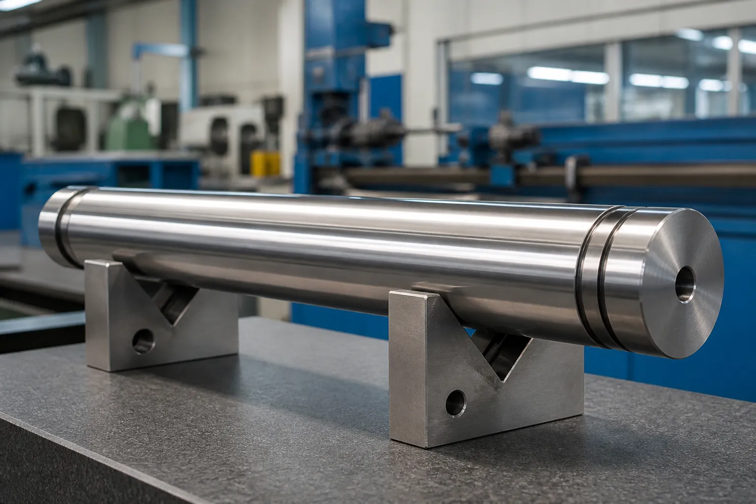
*Representative workshop photograph. Actual pillar dimensions, materials and correction limits follow the component drawing and a validated process study.*
What the Search Results Actually Show
Keputusan DataForSEO untuk mold guide pillar straightening are dominated by guide pillar manufacturers, mold guiding-system design articles and mold maintenance guides — not by straightening machine vendors. In practice, most mold shops either scrap a bent pillar and press in a new one, or send it to a general shaft-straightening service. That is economical for small standard pillars, but not for long custom pillars, pillars with special steel (SKD11, 1.2379, case-hardened 20Cr variants), or oversized pillars for large automotive molds where replacement lead time stops production.
| Guide Pillar Family | Konteks Biasa | Laluan Kejuruteraan |
|---|---|---|
| Standard catalog pillar (SUJ2 / 20Cr carburized) | Replacement item in general molds | Measure first; straighten only if replacement is slower or costlier |
| Long custom pillar for large automotive molds | Machined, dirawat haba, ground in-house | Inter-operational straightening between rough and finish grinding |
| Four-pillar die-set post (precision press dies) | Progressive die alignment | Batch measurement and correction with the die-set maker |
| Nitrided or DLC-coated pillar | High-cycle or low-lubrication molds | Restricted contact map; coating integrity is an acceptance gate |
| Bent pillar after mold crash | Mold repair workshop | Damage inspection (galling, retak) before any correction decision |
Define the Datum Chain Before Measuring
A guide pillar usually has three functional zones: the mounting journal with head and locating diameter pressed into the mold plate, the ground working diameter that runs in the guide bushing, and shoulder or end-face features. The straightness that matters functionally is the coaxiality of the working diameter relative to the mounting journal — a pillar can be “straight” as a bar and still assembled crooked if the press-fit journal is offset.
The measurement plan should therefore record:
- drawing datums and the fit specification of each diameter (press fit, transition fit, running clearance in the bushing);
- working-diameter straightness and roundness separately — an out-of-round diameter reads as runout but is not a bend;
- mounting-journal-to-working-diameter coaxiality, not just total indicated reading at one section;
- head face squareness to the axis, because a tilted head cocks the pillar in the plate;
- keadaan permukaan: pemarkahan, galling marks, seizure transfer, or grinding burn from previous rework;
- the actual running clearance in the mold’s guide bushing, which defines how much residual runout the application tolerates.
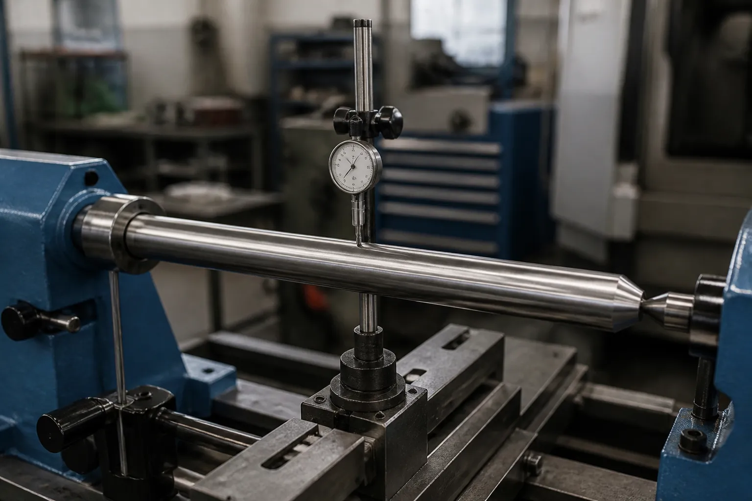
*Runout mapping between centers or on V-supports must separate local form error from center displacement; lihat LVDT multipoint shaft measurement for the sensor-layout logic.*
Membekukan Peringkat Proses
Selepas Berpusing Kasar, Sebelum Rawatan Haba
The pillar is soft and stock is generous. Correction is easy, but it can mask machining errors that heat treatment will re-introduce. Straightening here only buys a more uniform case depth and grinding allowance downstream.
After Heat Treatment — the Main Case
Mengkarburkan, quenching and tempering of slender pillars routinely produces bow of several tenths of a millimeter. This is the classic inter-operational straightening point: the ground diameter has not been produced yet, so contact tooling acts on grind stock, and the finish-grind pass still controls final size, kebulatan dan kemasan permukaan. Residual stress and springback are higher than in the soft state, so force-displacement recipes must be established on samples — the logic in meluruskan selepas rawatan haba applies directly.
Selepas Selesai Mengisar
The working diameter is now the functional surface, often with H5/g5-class fits and sub-micron roughness. Correction is still possible but restricted: only broad, radiused, soft-lined or protective tooling on approved zones, force ceilings validated by samples, and mandatory surface inspection afterward. If the bend exceeds what finish-stock correction can handle, regrind within size limits or replace.
From a Used Mold (Maintenance Case)
A pillar pulled from a crashed or seized mold may combine bend with galling, pemarkahan, adhesive wear and hidden cracks. Straightening must never be used to force a damaged surface back into service: visual and magnetic-particle or eddy-current inspection comes first, and the bushing is inspected as a pair because worn clearance and bent pillar produce identical symptoms — jamming, flash, parting-surface mismatch.
Classify the Deviation Before Pressing
| penyelewengan | Bukti | Correct Route |
|---|---|---|
| Global bow from heat treatment | Smooth single-arc runout map along the working diameter | Point-press correction at the apex, incremental, released recheck |
| Local bend after crash or press-in error | Sharp runout change over a short length | Localized correction with close supports; check for cracks first |
| Out-of-round working diameter | Runout changes with measurement section but not with angular position of the bend | Regrind or replace — not straightening |
| Journal-to-diameter coaxiality error | Working diameter straight, head/journal offset | Regrind the journal true, or re-machine datum; pressing on the head risks fracture |
| Galling or seizure damage | Scored, transferred metal on the running surface | Pelupusan: polish/regrind if depth allows, otherwise replace; straightening does not restore the surface |
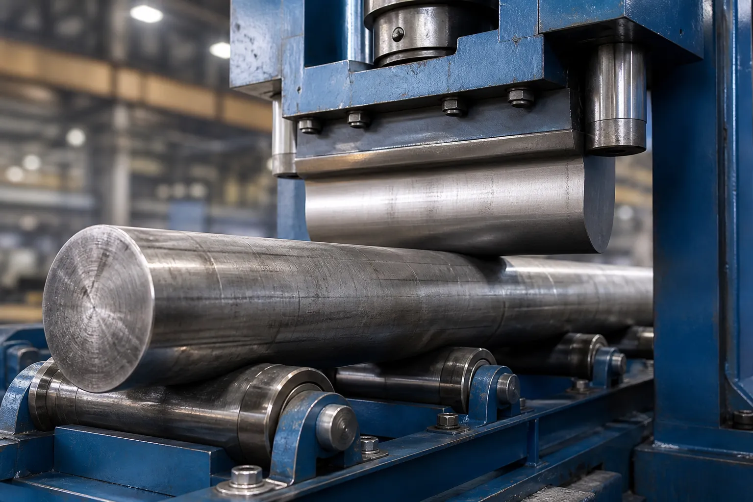
Correction Method and Protected Contact Map
Guide pillars are corrected by meluruskan titik-tekan: the pillar rotates on centers or V-rollers, sensors map runout, the axis of the bend is indexed to the press, and a small incremental load is applied at the bow apex between supports. Because the component is hardened, the process is force-controlled with displacement monitoring and explicit springback compensation — never a single “big hit”. The generic trade-offs between press and multi-roll straightening are compared in tekan straightening vs roller straightening.
Default no-press and no-support zones:
- the finished working diameter without protected tooling approval;
- head-to-shank fillet and shoulder transitions (fracture initiation sites);
- oil grooves, lubrication ports or vent features;
- nitrid, DLC-coated or chromed surfaces;
- any galled or heat-discolored zone;
- the head itself — pressing on the head to “push the pillar straight” cracks shoulders.
Approved zones are normally the grind-stock envelope of the working diameter and dedicated process collars. The contact map should be stored per part number and revision — a surface that is safe before finish grinding is protected afterward.
Closed-Loop Process
- Identify the pillar: part number, keluli, kekerasan, pentas, previous rework history.
- Clean and inspect: permukaan, galling, cracks by approved NDT where specified.
- Qualify the setup: centers or V-rollers, axial restraint, rotation repeatability.
- Map runout along the full working length, multiple sections, full rotation.
- Classify the deviation against the table above; route non-bend conditions out.
- Index the bend apex to the press; apply incremental force within validated ceilings.
- Lepaskan sepenuhnya, berputar, remeasure the complete map — loaded deflection is not the result.
- Iterate within the allowed correction count; berhenti pada kekakuan yang tidak normal.
- Verify released straightness, coaxiality to the journal, and surface condition.
- Record maps, force-displacement curves and disposition for traceability.
Springback on hardened slender pillars is significant and shifts with hardness and residual-stress state; the compensation logic is covered in pampasan springback meluruskan aci. Because pillar straightness interacts with tooling contact stress, roll and anvil geometry deserve the same scrutiny as the press itself — see surface-protection tooling in straightening.
Kriteria Penerimaan
- working-diameter straightness (TIR) within the drawing or die-set specification, measured released, full rotation, multiple sections;
- journal-to-working-diameter coaxiality within the assembly tolerance;
- no new indentations, bruising or polishing marks on running surfaces;
- roundness and surface finish unchanged where already ground;
- no crack indications where NDT is specified;
- diameter still within grind-stock or size limits after any localized correction;
- a dry-run fit check in the actual bushing: smooth travel over the full stroke without tight spots.
Common Pitfalls in Guide Pillar Straightening
- Chasing a dial reading instead of a map. Correcting the highest single runout value without mapping the full length overshoots the apex and S-curves the pillar; the second correction then fights the first.
- Pressing on the head. The fastest way to crack a pillar is using the head as a pressure surface. Load goes through approved body zones only.
- Ignoring out-of-round. An egg-shaped working diameter reads as runout under a fixed probe. Measure roundness at each section before concluding “bent”.
- Transferring recipes across hardness conditions. A force recipe validated on a soft blank under-corrects a hardened pillar and can over-stress a coated one. Every hardness and coating state needs its own recipe.
- Accepting loaded geometry. A pillar held under load in the press shows whatever the operator wants to see. Acceptance happens fully released, after rotation, on the complete map.
- Straightening a worn pair. Correcting the pillar while the bushing stays worn recreates the jam within days. The pillar-bushing pair is the unit of maintenance.
Data Diperlukan untuk Cadangan Teknikal
- pillar drawing and revision, with datum and fit specifications;
- gred keluli, rawatan haba, hardness and any coating or nitride layer;
- peringkat proses: post-heat-treatment, tanah, or recovered from a used mold;
- panjang, working diameter, slenderness ratio and mounting journal dimensions;
- incoming runout maps (sections and angles) and known bend origin;
- bushing fit specification and the mold’s alignment tolerance;
- zon hubungan yang diluluskan dan dilarang;
- remaining grind stock by diameter;
- required straightness acceptance value and measurement setup;
- lot sizes and cycle-time expectations;
- NDT or surface inspection requirements;
- representative samples for correction trials.
Soalan Lazim
Can a bent guide pillar be straightened, or must it be replaced?
Many heat-treatment bows and crash bends are correctable, but the decision needs the deviation class, hardness condition, surface state and remaining grind stock. A galled, cracked or repeatedly reworked pillar should be replaced — straightening restores geometry, not a damaged running surface.
How much runout is acceptable in a guide pillar?
Tiada nombor universal. The functional limit comes from the running clearance with the guide bushing and the mold’s alignment requirement — precision die sets specify far tighter limits than general-purpose molds. The acceptance value must come from the drawing or the die-set standard, not from a generic table.
Why does the pillar still jam after straightening passed?
Usually because only straightness was measured, while the real problem is out-of-roundness, a worn bushing, a tilted head face, or misaligned plate bores. Measure the pillar-bushing-plate system as a chain before and after correction.
Is press straightening safe on hardened pillar steel?
Yes within a validated envelope: incremental force, broad radiused contact, protected shoulders and fillets, full release before acceptance, and post-correction surface inspection. What is unsafe is uncontrolled hammering or pressing on the head and fillets.
Build the Solution Around the Datum Chain
A guide pillar straightens to its bushing fit, not to a generic pin spec: the running clearance between pillar and bushing defines how much residual geometry error the tool can still absorb. Hardness and surface condition narrow the correction options further – a carburized and ground pillar has no re-machining budget. Related mold-component processes are covered in the mold and die straightening hub, including the ejector pin straightening solution.
Send the pillar drawing, steel and hardness specification, peringkat proses, incoming runout maps and bushing fit requirements, plus representative samples. The measurement strategy and acceptance plan are built around the pillar-bushing pair, not the pillar alone.