
Lapu atspere ir apzināti izliekta. Darbs nav padarīt to ģeometriski taisnu; tas ir izgatavoto loksni vai salikto atsperu komplektu ievietot tā norādītajā brīvajā izliekumā, sānu izliekums un slodzes novirzīšanas logs, nesabojājot acis, centrālais caurums, konusveida sekcija, ar skrotīm notīrīta virsma vai termiski apstrādāts materiāls.
Uzticamam lokšņu atsperu iztaisnošanas mašīnas priekšlikumam vispirms ir jāatbild uz sešiem jautājumiem:
- Vai sagatave ir viena parastā lapa, meistara lapa ar acīm, paraboliska lapa vai salikts vairāku lapu iepakojums?
- Vai korekcija tiek veikta karstās izliekuma veidošanas laikā, pēc dzēšanas un rūdīšanas, pēc skrotis vai pēc montāžas?
- Vai zīmējums kontrolē brīvo izliekumu, sānu līkums, acu attiecības, vērpjot, slodzes augstums vai kombinācija?
- Kuras acis, sejas, caurumi un virsmas nosaka mērījumu atskaites punktu?
- Kuras zonas var atbalstīt vai saņemt spēku, neradot iespiedumus, plaisas vai virsmas bojājumi?
- Kā tiks mērīta pilnībā atbrīvotā daļa un, kur nepieciešams, slodzes pārbaude pirms pieņemšanas?
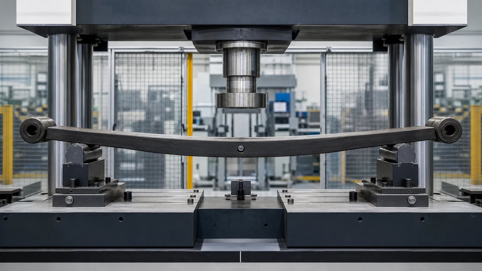
*Inženierzinātņu koncepcijas ilustrācija kontrolētai izliekuma korekcijai uz jaunas lokšņu atsperes. Tā nav klienta vietnes fotogrāfija vai darbības prasība. Mērķis paliek zīmējumā noteiktais loks; instrumenti, spēku, atbalstiem un pieņemšanas ierobežojumiem ir nepieciešami izmēģinājumu paraugi.*
Definējiet lapu pavasara saimi un piegādes stāvokli
| Apstrādājamo priekšmetu saime vai valsts | Galvenā atšķirība | Maršruts šajā lapā |
|---|---|---|
| Vienāda biezuma viena lapa | Salīdzinoši viendabīga sekcija, bet cilpas un cauruma īpašības ietekmē stingrību | Atsevišķu lapu mērīšana un korekcija |
| Meistara lapa ar izvērstām acīm | Acu asis un acs–centra attiecības ir funkcionālas | Aizsargāts acu atbalsts un datuma līgums |
| Paraboliska vai konusveida lapa | Sekcijas stingrība mainās visā garumā | Profilēts atbalsts un ierobežots vietējais spēks |
| Salikts vairāku lapu iepakojums | Starplapu berze, skavas un centrālā skrūve ietekmē reakciju | Brīvās arkas pārbaude un montāžas slodzes tests |
| Karsta lapa pirms dzēšanas | Camber veidojas termiskā procesa ietvaros | Karstās formēšanas/rūdīšanas instrumenti, nav galīgā aukstā korekcija |
| Rūdīta lapa pirms apdares | Tikai kontrolēta galīgā izliekuma vai sānu līkuma regulēšana | Primārās korekcijas kandidāts pēc kvalifikācijas |
| Lapa ar skrotīm vai pārklāta | Virsmas apstrādei jābūt aizsargātai | Kontaktpersonu pārskatīšana un iespējamā pakārtotā pārstrāde |
| Lietots, nokarājusies vai saplaisājusi transportlīdzekļa atspere | Noguruma vēsture un servisa bojājumi nav zināmi | Ārpus šī jaunās ražošanas risinājuma |
Publiskie ražošanas maršruti no Moritas, Nakano pavasaris, Canara Workshops un Jones Springs novieto izliekumu, kas veidojas termiskās apstrādes secībā vai tās tuvumā, kam seko apdare, montāža un testēšana. Tas atbalsta ražošanas korekcijas procesu; tas nerada vienu temperatūru, cietības vai spēka recepte universāla.
Izprotiet, kur procesā tiek ievadīta formas kļūda
Karstās izliekuma formēšana un dzēšana
Apsildāmo loksni var veidot pret iepriekš iestatītu izliekuma instrumentu un tādā stāvoklī dzēst. Instrumenta iestatīšana, daļas atrašanās vieta, temperatūras sadalījums un dzēšanas uzvedība ietekmē atbrīvoto loku. Šajā posmā radušajai problēmai vispirms ir jāizraisa formēšanas un termiskās apstrādes pārskatīšana.
Rūdīšana un atlikušā stresa pārdale
Termiskā apstrāde maina spēku un pārdala stresu. Lapa, kas atbilst instrumentam zem slodzes, var pārvietoties pēc izkraušanas vai rūdīšanas. Tāpēc korekcijai ir nepieciešams atbrīvots mērījums, ne tikai preses pozīcija.
Acu ripināšana, Caurumu veidošana un konusu veidošana
Izveltītas acis, centra caurumi, gala iezīmes un konusveida sekcijas rada stingrības pārejas. Tie nodrošina arī funkcionālas atsauces, kuras var izkropļot slikta spēka izvietojuma dēļ.
Shot Peening, Apstrāde un montāža
Spriegojuma pusei parasti tiek izmantota skrotis, lai uzlabotu veiktspēju noguruma gadījumā. Apstrāde, skavas, centra skrūves un starplapu kontakts var mainīt šķietamo brīvo formu. Ja pēc pīlinga tiek ierosināta korekcija, klienta procesa īpašniekam ir jāizlemj, vai ir nepieciešama atkārtota pārbaude vai papildu pārbaude.
Atsevišķs Camber, Sānu izliekums un noslogota forma
Bezmaksas Kembers
Brīvais izliekums ir neslodzes loka vai augstums, ko nosaka zīmēšanas un pārbaudes metode. Tas jāmēra no noteiktās acs, gala vai stiprinājuma atskaites punkti. Tas nav tas pats, kas padarīt lapu plakanu.
Sānu līkums
Sānu līkums ir sānu novirze no norādītās gareniskās plaknes. Tam nepieciešams atsevišķs skatīšanās virziens un mērījumu celiņš no izliekuma. Preses iestatījums, kas maina vertikālo izliekumu, var neizlabot sānu priekšgalu.
Savērpšanās un acu attiecības
Twist, acs ass paralēlisms un acs līdz centram var būt zīmēšanas raksturlielumi. Tie ir jāuzskata par klienta definētiem laukiem līdz datumam, tiek piegādāta sadaļa un mērinstrumentu metode; šī lapa nepiešķir universālu ierobežojumu.
Slodzes augstums un slodzes novirze
Salikts iepakojums maina formu zem slodzes. Piekrauts augstums, likme un pastāvīgais komplekts ir funkcionālās pārbaudes izejas, neaizstāj atbrīvoto ģeometriju. Atspere var izturēt brīvo izliekumu un tomēr neizdoties slodzes testā, vai otrādi.

*Inženierzinātnes koncepcijas ilustrācija atbrīvotā izliekuma mērījumam ar aizsargātiem acu balstiem un neatkarīgiem sensoriem. Attēls attēlo tikai mērījumu loģiku; faktiskie dati, stabilizācijas laiks un mērinstrumenta korelācija izriet no kontrolētā rasējuma.*
Izveidojiet datumu un mērījumu līgumu
Mērījumu plānā jādefinē:
- lapu ģimene, zīmējumu pārskatīšana un izsekojamība;
- materiāls, cietība, termiskās apstrādes un virsmas apstrādes stāvoklis;
- kopējais garums, platums, biezums un konusveida profils;
- acs diametrs, acs ass attiecības un centra-cauruma atrašanās vieta;
- brīvā izliekuma definīcija, horda vai nulles līnija un mērījumu stacijas;
- sānu izliekums un jebkura pagrieziena mērīšanas metode;
- atbalsta pozīcijas, kontakta platums, spilventiņu materiāls un ierobežošanas spēks;
- spriedzes puse, nošautām zonām, pārklājumi un aizsargātās virsmas;
- tīrīšana, temperatūra un stabilizācijas stāvoklis;
- atkārtojamība pēc pilnīgas atbrīvošanas un pārvietošanas;
- montāžas stāvoklis, noteiktā testa slodze un slodzes-nolieces metode.
Zīmējums izlemj, vai acu centrā, gala zemes, galvenā veidne vai cits aprīkojums nosaka atskaites punktu. Neizmantojiet vienkāršākos atbalsta punktus, nepārbaudot to funkcionālo nozīmi.
Pirms spēka pielietošanas klasificējiet stāvokli
| Novērotais stāvoklis | Iespējamais cēlonis | Nepieciešamais maršruts |
|---|---|---|
| Vienota izliekuma nobīde gar lapu | Karstās formēšanas rīks, remdēšanas vai temperamenta reakcija | Procesa pārskatīšana un ierobežota izliekuma korekcija |
| Vietējais augstais vai zemais reģions pārejas tuvumā | Konusveida, acu vai cauruma stīvuma izmaiņas | Profilēts atbalsts un vietējās korekcijas, kurās tiek izmantotas funkcijas |
| Sānu loks ar pieņemamu izliekumu | Apstrāde, veidojošs vai asimetrisks ierobežojums | Īpaša sānu līkuma iestatīšana |
| Izliekums mainās pēc atbrīvošanas | Springback, nestabils atbalsts vai nepietiekama stabilizācija | Izmēra-pareizi-atbrīvošanas cilpa un receptes apskats |
| Acu attiecības ir izslēgtas, kamēr loks iet garām | Acu veidošanas vai atskaites kļūda | Acīm raksturīgs izvietojums; nespiediet loku akli |
| Brīvā forma iztur, bet slodzes pārbaude neizdodas | Materiāls, termiskā apstrāde, biezums, montāžas vai komplekta jautājums | Kvalitātes un procesa pārbaude ārpus ģeometrijas korekcijas |
| Iespiedumi, plaisas, dekarbonizācija vai nopietni virsmas bojājumi | Materiāla vai procesa defekts | Kvalitatīvs izvietojums pirms korekcijas |
| Lietotai atsperei ir noslīdējums vai nezināma servisa vēsture | Noguruma vai pārslodzes vēsture | Izslēgt no jaunas daļas labojumu darbības jomas |
Aizsargājiet funkcionālās un nogurumam kritiskās zonas
Noklusējuma aizsargātās vai pārskatīšanas zonas
- izbolīja acis, acu malas un uzstādītas bukses;
- centrālais caurums, centra skrūvju sēdeklis, skavas un atsitiena skavas;
- konusveida vai paraboliskas biezuma pārejas;
- nošūta spriegojuma virsma un gatavās malas;
- pārklāts, krāsotas vai pret koroziju aizsargātas virsmas;
- pastmarkas, izsekojamības zīmes un pārbaudes punkti;
- saplaisājusi, niķoja, pārkarsēts, dekarbonizētas vai korozijas vietas.
Potenciāli apstiprinātas kontaktu zonas
- plašās zemes, kas norādītas zīmējumā vai stiprinājuma plāna paraugā;
- maināmi rādiusa spilventiņi, kas pieskaņoti lapas platumam un lokam;
- zonas, kuras vēlāk apstrādā, kad process to atļauj;
- ir pierādīts, ka atbalsta zonas neatzīmē atsperi vai lokāli nesaplacina.
Mīksts paliktnis nepierāda nulles bojājumus. Kontakta spiediens, bīdāmās, pikaps, reprezentatīvos paraugos jāpārbauda vietējās saplacināšanas un atlikuma zīmes.
Izmantojiet atbrīvoto slēgtā cikla korekcijas procesu
- Nosakiet lapu ģimeni, rasējuma pārskatīšana un procesa stāvoklis.
- Apstipriniet, ka detaļa ir jauna ražošanas detaļa bez plaisām vai diskvalificējošiem bojājumiem.
- Notīriet to un stabilizējiet to norādītajā stāvoklī.
- Atrodiet apstiprināto aci, gala vai stiprinājuma atskaites punkti bez pārspīlēšanas.
- Izmēriet brīvo izliekumu, sānu izliekums un visi zīmējumā noteiktie sekundārie raksturlielumi.
- Klasificējiet kļūdu un atlasiet apstiprināto atbalsta diapazonu, kontakta zona un korekcijas virziens.
- Pielietojiet vienu ierobežotas preses korekciju, vienlaikus uzraugot spēku un pārvietojumu.
- Pilnībā izkraujiet lapu un ļaujiet norādītajam atveseļošanās periodam.
- Atkārtoti mērīt no tiem pašiem datiem.
- Atkārtojiet tikai labojumu skaita robežās, bez progresa, apgrieztās korekcijas un virsmas riska robežas.
- Pilnīgs vizuālais, dimensiju, cietība, plaisa vai cita nepieciešamā pārbaude.
- Par pavasara iepakojumu, salieciet un veiciet norādīto iestatījumu, skrāpēšana vai slodzes pārbaude.
- Uzglabāt pirms/pēc ģeometrijas, spēka pārvietošana, iterācijas un galīgais izvietojums.
Izvēlieties pareizo korekcijas arhitektūru
Kontrolēta preses izliekuma korekcija
Hidrauliskā vai servoprese ar regulējamām reakcijām ir visspēcīgākais pierādījums nelielai galīgajai izliekuma korekcijai. Iekārtai ir jāsaglabā tīša loka un jākontrolē atspere, veicot atkārtotus veiktos mērījumus.
Īpaša sānu izliekuma korekcija
Sānu priekšgalam var būt nepieciešams horizontāls slodzes ceļš, malu balsti vai pārorientēta armatūra. To nevajadzētu uzskatīt par vienu un to pašu asi kā izliekuma korekciju.
Hot Camber un Quench Tooling
Kad nepieciešamā formas maiņa pieder karstajai formēšanai, Pareizais risinājums ir integrēta izliekuma veidošanas un dzesēšanas armatūra. Šis procesa logs atšķiras no aukstās galīgās korekcijas pēc rūdīšanas.
Rullīšu iztaisnošana
Nepārtrauktā rullīšu iztaisnošana ir paredzēta galvenokārt sagatavēm, kuru mērķis ir taisna gareniskā ass. Gatavai lokšņu atsperei ir izstrādāts loks un mainīgas īpašības, tāpēc rullīšu iztaisnošana nav noklusējuma izvēle. Skat preses iztaisnošana vs rullīšu taisnošana par atlases robežu.

*Inženierzinātnes koncepcijas ilustrācija vairāku lapu iepakojumam kontrolētā slodzes pārbaudes stacijā. Tā nav piegādāta mašīnas fotogrāfija. Slodzes punkti, atbalsta, iepriekšēja ielāde, cikliem un pieņemšanas joslām ir nepieciešama klienta testa specifikācija.*
Atsevišķi pārbaudiet atsevišķas lapas un saliktos iepakojumus
Atsevišķas lapu atbrīvošanas pārbaudes
- brīvs izliekums vai loks norādītajā atskaites punktā un stacijās;
- sānu izliekumu un jebkuru zīmējumā noteikto pagriezienu;
- acs diametrs, acs ass attiecības un centra-cauruma pozīcija;
- platums, biezums, konusveida un lokālais profils pēc korekcijas;
- kontaktu zīmes, malu stāvoklis un virsmas apstrādes integritāte;
- cietība, plaisas vai citas NDT pārbaudes, ja nepieciešams.
Saliktās pavasara pakotnes izlaišanas pārbaudes
- bez montāžas arkas un kreisās/labās attiecības, kur piemērojams;
- centrālā skrūve, skavas, klipus un acu/bukses stāvoklis;
- norādīto iestatījumu vai skraidīšanas secību;
- slodzes augstums, slodzes novirzes vai atsperes ātruma rezultāts;
- pastāvīgais komplekts pēc pilnīgas izlaišanas;
- galīgais vizuālais, izmēru un izsekojamības ieraksti.
Canara Workshops publiski apraksta izliekuma korekciju, hidrauliskā sānu līkuma korekcija, montāžas arkas korekcija un atkārtota skrambēšana tā ražošanas maršrutā. Nakano un Morita arī parāda galīgo slodzes testu lokšņu atsperu ražošanā. Šie avoti nosaka nepieciešamību pēc atsevišķiem ģeometrijas un funkcionāliem vārtiem; the customer's drawing controls the actual sequence and limits.
Konfigurējiet šūnu ap kvalificēto ģimeni
| Šūnas funkcija | Lapu atsperes prasība |
|---|---|
| Identifikācija | Lapu ģimene, zīmējums, materiāls, termiskā apstrāde, virsmas stāvoklis un izsekojamība |
| Apstrāde | Platumu atbalstoša transmisija, kas aizsargā acis, malām un nošūtām virsmām |
| Mērīšana | Atbrīvots izliekums, sānu līkums, acs/centra attiecības un izvēles vērpjot |
| Klasifikācija | Globālā izliekuma nobīde, lokāla loka kļūda, sānu priekšgala, datuma kļūda un atspere |
| Labojums | Regulējami presēšanas balsti ar ierobežotu spēku/nobīdi; atsevišķs sānu līkuma maršruts |
| Aizsardzība | Acis, centrālais caurums, konusveida pārejas, spriegojuma virsma, pārklājuma un izsekojamības zīmes |
| Verifikācija | Atbrīvota ģeometrija un montāžas iestatījums/slodzes tests, kur norādīts |
| Dati | Pirms/pēc formas, recepte, spēka pārvietošana, iterācijas, apskate un iznīcināšana |
Nepieciešamā priekšlikuma ievade
Pirms aprīkojuma izvēles nosūtiet tālāk norādīto:
- kontrolēti lapu un montāžas rasējumi;
- konvencionālais, meistars, parabolisko un iepakojuma ģimeņu saraksts;
- materiāls, termiskā apstrāde, cietība un skrotis trase;
- korekcijas posms un pakārtotā apdares secība;
- brīvs izliekums, sānu līkums, vērpjot un acu attiecību definīcijas;
- apstiprināts datums, atbalsta un kontaktu kartes;
- reprezentatīvi ienākošās formas mērījumi;
- atļauto labojumu skaits, virsmas zīmes un noraidīšanas kritēriji;
- nepieciešamā cietība, plaisu vai citu NDT pārbaudi;
- iepakojuma montāža, iestatījumu, skraidīšanas un slodzes pārbaudes specifikācija;
- takts, iekraušana, ziņošanas un izsekojamības saskarnes;
- pārstāvis labs, marginālie un noraidītie paraugi.
The Automobiļu detaļu risinājumi lapa sniedz plašāku transportlīdzekļa sastāvdaļu kontekstu. Šī lapa paliek specifiska jaunām lokšņu atsperēm un to ražošanas korekcijas maršrutam.
Paraugu pārbaudes pieņemšana pirms ražošanas izlaišanas
Izmēģinājumam vajadzētu aptvert lapu ģimeni, garums, platums, konusveida, termiskās apstrādes stāvoklis, ienākošā izliekuma un sānu izliekuma aploksne. Tam vajadzētu pārbaudīt armatūras atkārtojamību, datuma korelācija, spēka-pārvietošanas reakcija, atspere, iterācijas ierobežojumi, acu un virsmas aizsardzība, atbrīvota ģeometrija un montāžas slodzes uzvedība.
Izmantojiet iztaisnošanas parauga pārbaude un pieņemšanas rokasgrāmata iesaldēt testa matricu un pierādījumu paketi pirms ražošanas izlaišanas.
Inženiertehniskā robeža
Šis risinājums aptver kontrolētu jaunu lokšņu atsperu formas korekciju ražošanas laikā. Tas nesertificē lietotu atsperi turpmākai apkopei, atjaunot noguruma dzīvi, salabot plaisas, transportlīdzekļa braukšanas augstuma garantija, pārveidot vienu slodzes vērtību citā vai aizstāt termisko apstrādi, nošaušanas un galīgās slodzes pārbaudes vadības ierīces.
Spēks, atbalsta laidums, kontakta ģeometrija, precizitāte, cikla laiks, atveseļošanās periods un labojumu skaits ir priekšlikuma rezultāti. Tiem jānāk no zīmējumiem, procesa stāvoklis, samples and the customer's gauge—not from a generic competitor specification.
Pieprasiet lapu pavasara iztaisnošanas pārskatu
Nosūtiet lapu saimes tabulu, zīmējumi, termiskās apstrādes posms, brīvā izliekuma un sānu līkumu dati, aizsargājamās zonas, montāžas testa specifikācija un reprezentatīvie paraugi. Mēs atgriezīsim piedāvāto mērījumu līgumu, korekcijas arhitektūra, paraugu pārbaudes matrica un aprīkojuma konfigurācija pārskatīšanai.