
Betona un āmura urbji apvieno garu tērauda korpusu ar spirālveida viļņiem, karbīda griešanas konstrukcija un rievots vai profilēts piedziņas kāts. Šīs īpašības padara apstrādājamo priekšmetu ļoti atšķirīgu no vienkārša apaļā stieņa. Mērīšanas zonde var sekot flautai, nevis patiesajai ķermeņa asij, savukārt nepareizi novietots balsts vai prese var sabojāt karbīda savienojumu, griešanas galva, flautas mala vai SDS savienojums.
Tāpēc betona urbjmašīnas iztaisnošanas risinājums ir jāizstrādā, ņemot vērā precīzu uzgaļu saimi un ražošanas posmu. Tam vajadzētu izmērīt zīmējumā definētu raksturlielumu, labot tikai apstiprinātās tērauda zonas un pēc korekcijas pārbaudīt gan ģeometriju, gan stāvokli.
Betona urbji nav viena viendabīga sagatave
Oficiālie produktu klāsti parāda būtiskas konstrukcijas atšķirības. Bosch uzskaita divu griezēju volframa karbīda plāksnes, četru griezēju pilna karbīda galviņas, divi- un četru flautu korpusi, īpaši metinātie uzgaļu savienojumi un SDS Plus kāti. Hilti uzskaita cietā karbīda vairāku griezēju galviņas un četrkāršās spirāles. DEWALT piedāvā karbīda uzgaļus, atvērtas galvas konstrukcijas un iegareni četru flautu korpusi.

Attēls ir īsts sīktēla rāmis no projekta elektriskā āmura urbja video. Tas apstiprina rievotu urbi, turēšanas stacija un korekcijas mehānisms. Tas nenosaka bitu materiālu, izmēriem, precizitāte vai cikla laiks.
| Sagataves iezīme | Iztaisnošanas sekas |
|---|---|
| Lodēta/metināta karbīda plāksne | Šuvei un karbīdam parasti jāatrodas ārpus presēšanas/atbalsta zonas |
| Pilna karbīda vairāku griezēju galva | Augstākas vērtības trauslajai galvai ir nepieciešama kontrolēta apstrāde un trieciena aizsardzība |
| Divas- vai četru flautu spirāle | Kontakta mērījumi mainās ar aksiālo un leņķisko stāvokli |
| Samazināts serdes vai mainīgs flautas dziļums | Liekšanas stingrība mainās visā darba garumā |
| SDS Plus/Max vai cits piedziņas kāts | Slotes un piedziņas funkcijas nav vienkāršs cilindrisks atskaites punkts |
| Apaļš, plakans vai patentēts patronas gals | Nepieciešams variantam specifisks lokators un palaišanas definīcija |
| Rūdīta vai ar virsmu apstrādāta tērauda korpuss | Izmaiņas atsperes, marķēšanas un plaisu risks |
Nosakiet ražošanas posmu
| Skatuves | Potenciālais mērķis | Galvenais ierobežojums |
|---|---|---|
| Tērauda sagatave pirms rievošanas | Pirms apstrādes/formēšanas izveidojiet tiešu atsauci | Fināla flautas/galvas attiecības vēl nav |
| Pēc flautas formēšanas | Pirms karbīda piestiprināšanas izlabojiet ķermeņa deformācijas | Mērīt caur periodisku spirālveida profilu |
| Pēc termiskās apstrādes | Pareiza termiskā deformācija | Cietība, atsperes un plaisu ierobežojumiem ir nepieciešama validācija |
| Pēc karbīda piestiprināšanas | Pareiza montāžas vai savienojuma deformācija | Aizsargājiet karbīdu un lodētu/metinātu savienojumu |
| Pēc slīpēšanas/pārklāšanas | Iepazīstieties ar galīgo ģeometriju | Ļoti stingra virsmas un progresīva aizsardzība |
Drošākais un spējīgākais posms automātiski nav pēdējais. Ja process atkārtoti saliek bitus pēc agrākas korekcijas, projektā jānovērš šis augšējais cēlonis vai jāpārvieto iztaisnošanas darbība atbilstošā vēlākā posmā.
Nepieciešamās projekta ievades
| Ievade | Nepieciešamā detaļa |
|---|---|
| Zīmējums | Pārskatīšana, kontrolēta funkcija, datums and tolerances |
| Maza ģimene | Diametrs, kopējais/darba garums, flautu skaits un pamatprofils |
| Griešanas galva | Karbīda plāksne/pilna galva, griezēju skaits, savienojuma veids un aizliegtās zonas |
| Kāts | SDS Plus/Max, apaļa, sešstūra vai patentēta savienojuma ģeometrija |
| Materiāls maršruts | Tērauda marka, sacietēšana, karbīda piestiprināšanas un pārklājuma secība |
| Ienākošais līkums | Lielums, plakne un aksiālais sadalījums no reprezentatīvajām partijām |
| Galīgā pārbaude | Taisnuma/izskrējiena/profilēšanas metode, mērierīce, orientācija un izšķirtspēja |
| Ražošanas apjoms | Varianti, izvades mērķis, iekraušana, nomaiņa un izsekojamība |
Iepriekšējās lapās nebija pārbaudīta izmēra, cietība, precizitāti vai cikla datus. No video nevajadzētu secināt neko.
Taisnīgums, Izskrējiena un uzgaļu izlīdzināšana ir atšķirīga
| Raksturīgs | Ko tā novērtē | Nepieciešama definīcija |
|---|---|---|
| Ķermeņa taisnums | Izvēlētā virsmas elementa vai atvasinātās ķermeņa ass forma | Kontrolētais garums un flautas zinoša vērtēšanas metode |
| Radiālais izskrējiens | Virsmas izmaiņas, griežot ap nulles punktu | Datu pazīmes, zondes/optiskā pozīcija un leņķiskā paraugu ņemšana |
| Izlīdzināšana no galiņa līdz kātam | Saikne starp griešanas galvu un piedziņas kāta asi | Galvas funkcija, kāta atskaites punkts un pieņemšanas zona |
| Flautas profils/svins | Spirālveida elementu ģeometrija | Aksiālais diapazons, leņķiskās atskaites un profila metode |
| Funkcionālā rotācija | Uzvedība apstiprinātā patronā vai testa vārpstā | Čaks, ievietošanas dziļums, ātrums un izmērītā vieta |
ISO 1101 definē ģeometriskās specifikācijas valodu, bet klienta zīmējumā ir jānorāda faktiskā pielaide. Mašīna nevar “nodrošināt taisnumu vai izskrējienu”, kamēr šī izvēle un atskaites punkts nav skaidri norādīti.
Flautai saprotami mērījumi ir ļoti svarīgi
Kontakta zonde, kas pieskaras rotējošai spirālei, paceļas un nokrīt ar flautu. Šis periodiskais signāls var būt daudz lielāks par novērtēto viduslīnijas līkumu. SDS sloti un plaknes rada tādu pašu problēmu piedziņas galā.
Mērījumu koncepcijā jāizmanto viens vai vairāki no tālāk norādītajiem:
- noteikta gluda cilindriska zeme, ja rasējums to nodrošina;
- kontrolēta leņķiskā indeksācija, lai izmērītu to pašu flautas/zemes attiecības;
- vairāki optiskie silueti un kalibrēts viduslīnijas/profila modelis;
- bezkontakta sensors apstiprinātās aksiālās pozīcijās;
- galvenais patrona vai centri, kas attēlo funkcionālo atskaites punktu;
- filtrēšana, kas ir pārbaudīta attiecībā pret zināmajām atsauces daļām, nav atlasīts tikai tāpēc, lai diagramma izskatītos gluda.
Zondes spēks, atbalsta pozīcijai un iespīlēšanas spēkam jābūt arī pietiekami zemam, lai slaidais urbja korpuss netiktu saliekts paša mērījuma rezultātā.
Ieteicamais slēgtā cikla iztaisnošanas process
1. Identificējiet bitu ģimeni
Operators vai automatizācija pārbauda bitu diametru, garums, flautas/galvas dizains un kāta tips. Recepte izvēlas lokatoru, atbalsta, apstiprinātās mērījumu pozīcijas, korekcijas limiti un aizliegtās zonas.
2. Ielādējiet, nesaskaroties ar griešanas malām
Paplāte, žurnāla vai padevēja instrumenti piedāvā vienu uzgali, nesaduroties ar karbīdu pret karbīdu. Uz galvas un flautas malām nav cietu atduru. Automātiskā barošana ir jāizmēģina ar reālu garumu, virsmas, eļļas un sapīšanās apstākļi.
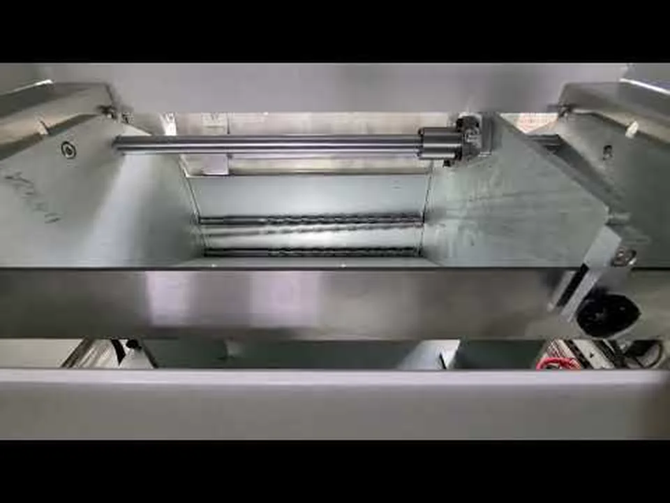
Šis rāmis ir iegūts no pareizā publiskā betonēšanas mašīnas video un parāda padeves apgabalu. Tas nepierāda bez uzraudzības veiktu barošanu, jaudu vai pārslēgšanās laiku.
3. Izveidojiet atskaites punktu
Uzgaļu notur apstiprināta gluda kāta zona, centri vai funkcionāls interfeiss. SDS sloti tiek indeksēti, kad tie ietekmē lokatoru. Armatūra nedrīkst nospiest uzgali mākslīgi taisnā stāvoklī.
4. Izmēriet ienākošo ģeometriju
Kontakta vai bezkontakta sensori apkopo datus tikai apstiprinātās pozīcijās un orientācijās. Kontrolieris atdala atkārtojamo flautas/profila parakstu no lieces raksturlieluma un saglabā ienākošo rezultātu.
5. Izvēlieties balstus un korekcijas punktu
Balsti un prese iedarbojas uz apstiprinātajām tērauda virsbūves zonām. Griešanas galva, karbīda savienojums, flautas mala, samazināts kodols, termiskās apstrādes pārejas un SDS funkcijas ir izslēgtas, ja vien rasējums un parauga tests nepārprotami apstiprina kontaktu.
6. Izmantojiet ierobežotu punktu korekciju
Prese pieliek kontrolētu pārvietošanu vai spēku. Rūdīts, slaidiem un rievotiem uzgaļiem nepieciešama pakāpeniska korekcija ar maksimālo spēku/gājienu un atkārtojuma ierobežojumiem. Viena smaga korekcija nav vispārēja stratēģija.
7. Atkārtoti mērīt, izmantojot to pašu atskaites punktu
Daļa tiek pārmērīta, nemainot datu loģiku. Turpmāka korekcija ir atļauta tikai apstiprinātajā logā. Detaļas ar pārmērīgu ienākošo līkumu, nestabili rādījumi vai negaidīta atspere tiek atdalīti pārskatīšanai.
8. Pārbaudiet stāvokli un darbību
Pēdējās pārbaudes var ietvert ģeometriju, karbīda/šuvju pārbaude, flautas un pārklājuma stāvoklis, plaisu pārbaude un funkcionālā patronas rotācija. Nepieciešamais komplekts atbilst ražošanas posmam un kvalitātes plānam.
Īsta betona urbja taisnošanas video
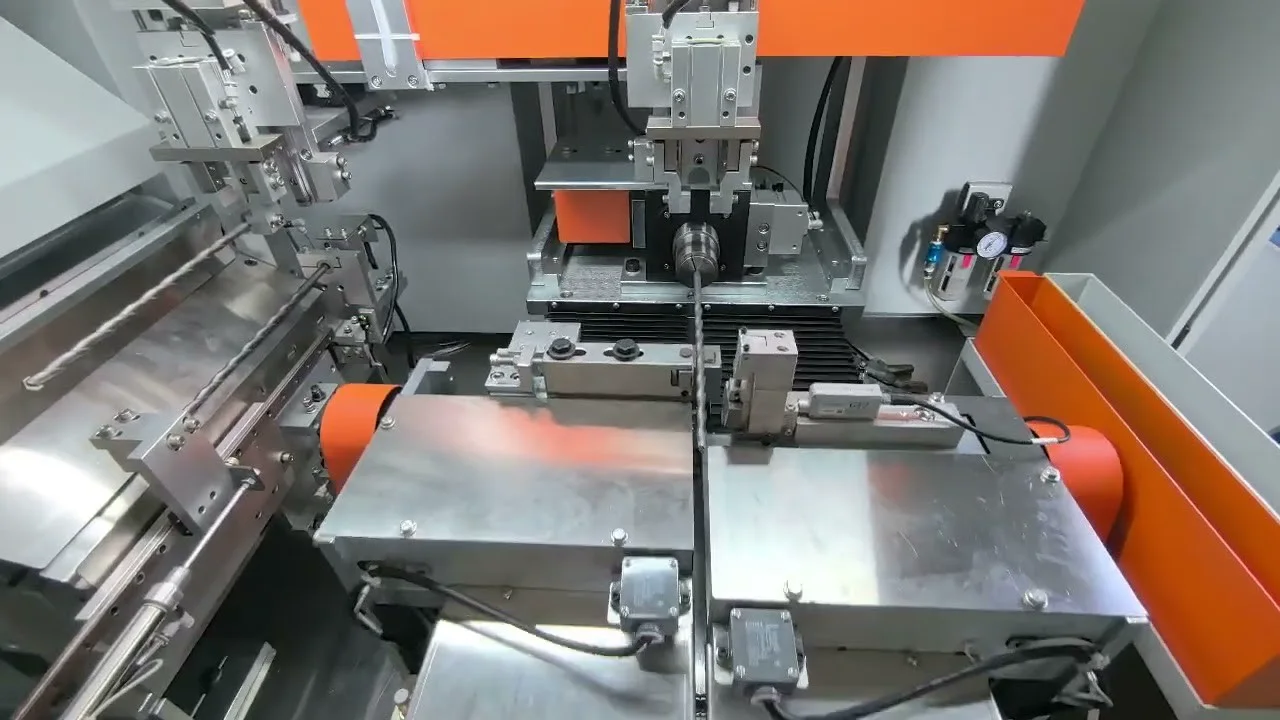
Nākamajam videoklipam ir nosaukums Automatic Straightening Machine for concrete bit kanālā Taisnošanas mašīna. Tas parāda betona/rotācijas āmura urbja šūnu ar padevi, turēšanas un korekcijas iekārtas. Tas nepierāda nekādu īpašu precizitāti, izvade, raža vai klienta rezultāts.
Virsma, Karbīda un locītavu aizsardzība
| Risks | Kontrole |
|---|---|
| Apstrādājot karbīda uzgalis nošķelts | Atdaliet detaļas un izmantojiet galvas atstarpes instrumentus |
| Lodētais/metinātais savienojums ir pārslogots | Definējiet izslēgšanas attālumu un maksimālo korekcijas momentu |
| Flautas maliņa iespiedusies | Izmantojiet ar profilu saderīgus atbalstus un apstiprinātas kontaktu zonas |
| Rūdīta ķermeņa plaisas | Ierobežojiet ienākošo līkumu un korekciju; pievienojiet nepieciešamo plaisu pārbaudi |
| SDS slots tiek izmantots kā viltus atskaites punkts | Atrodiet uz zīmējumiem apstiprinātām virsmām vai funkcionālas patronas saskarnes |
| Zonde seko spirālei | Izmantojiet indeksētu/profilu apzinošu vai bezkontakta mērījumu |
| Pārklājums vai apdare marķēta | Apstipriniet kontaktu materiālu, spiediena un pārbaudes standarts |
| Uzgalis atsperas no armatūras | Kontrolējiet iespīlēšanu un aizsargājiet korekcijas zonu |
Punktu korekcija vai rullīšu iztaisnošana?
| Lēmuma faktors | Punktu korekcijai var būt priekšroka, kad | Rullīšu iztaisnošanu var novērtēt, kad |
|---|---|---|
| Liekumu sadalījums | Augstos punktus var izmērīt individuāli | Izliekums ir sadalīts pa pietiekami vienmērīgu ķermeni |
| Ģeometrija | Galva, flautām un kātam ir nepieciešams selektīvs kontakts | Ir pieejams nepārtraukts rullīšu kontakta ceļš |
| Mērīšana | Nepieciešama slēgtā cikla atkārtota mērīšana | Pirms/pēc līnijas mērījuma var pārbaudīt rezultātu |
| Virsma | Ir pieņemams lokāls aizsargāts kontakts | Ir atļauts nepārtraukts veltņa kontakts |
| Produktu maisījums | Vairākiem variantiem ir nepieciešamas īpašas receptes/rīki | Stabilām lielāka apjoma ģimenēm ir kopīgs apstiprināts ruļļa iestatījums |
Karbīda galva automātiski neaizliedz visu iztaisnošanu, bet tas sašaurina drošā kontakta un korekcijas logu. Process tiek izvēlēts no paraugiem un zīmējuma, nevis no universāla saukļa.
Pārbaudes un pieņemšanas plāna paraugs
Reprezentatīvie paraugi
- mazākais korpuss/kodols un garākais elastīgais variants;
- katra flautas skaits, karbīda galvas dizains un kātu saime;
- katrs termiskās apstrādes un pārklājuma stāvoklis;
- paraugi visā reālajā ienākošā līkuma sadalījumā;
- vairākas ražošanas partijas, kur savienojuma kropļojumi vai atspere var atšķirties;
- robeždaļas, kas atrodas netālu no paredzētās korekcijas robežas.
Nepieciešamie pierādījumi
| Ieraksts | Pieņemšanas pierādījumi |
|---|---|
| Daļas identitāte | Zīmējuma pārskatīšana, variants, materiāla maršruts un partija |
| Ienākošā ģeometrija | Datum, orientācija, pozīcijas un izmērītās vērtības |
| Instrumenti | Lokators, atbalsta, preses un aizliegto kontaktu zonas |
| Labojumu vēsture | Atrašanās vieta, spēks/pārvietošanās un atkārtojumu skaits |
| Galīgā ģeometrija | Tāda pati mašīnas iestatīšana, kā arī korelācija starp klientu |
| Galvas/locītavas/flautas stāvoklis | Saskaņots vizuālais, palielināts vai NDT rezultāts |
| Funkcionāls rezultāts | Patronas griešanās vai pakārtota pārbaude, ja nepieciešams |
| Ražošanas izmēģinājums | Izmērītais cikls, barošanas stabilitāte, maiņa un pieejamība |
Automatizācija un maiņa
| Līmenis | Tipisks apjoms |
|---|---|
| Manuāla iekraušana | Operatora slodzes; mašīnu pasākumi, labo un pārbauda |
| Žurnāls/paplāte | Kontrolēta prezentācija stabilai ģimenei |
| Automātiskā šūna | Barošana, identifikācija, mērīšana, labošana un šķirošana |
| Izsekojamā šūna | Daļa/partija, recepte, mērījumu un korekciju ieraksti |
Mainot diametru vai garumu, var būt nepieciešami balsti, Čaks, sensora pozīcijas un presēšanas instrumenta maiņas. Nomaiņa no divu griezēju SDS Plus uzgaļa uz pilna karbīda četrgriezēju vai citu kātu saimi nav tikai PLC receptes maiņa.
Kas nav universāls solījums
Pirms rasēšanas pārskatīšanas un parauga apstiprināšanas, šis risinājums nesola:
- viena pielaide, cikla laiks vai ražība katram betona urbjam;
- ka taisnums un izskrējiens ir savstarpēji aizstājami;
- katra ienākošā līkuma lieluma korekcija;
- nulles karbīda bojājumi, locītavu, flauta, pārklājums vai kāts;
- automātiska barošana jebkuram garumam un galvas stilam;
- ka PLC vadība novērš programmatūru, instrumenti vai maiņas darbi;
- fiksēts darbaspēka ietaupījums vai ražošanas uzlabošana;
- drošs lietoto remonts, trieciena bojāti vai saplaisājuši urbji.
Saistītās lietojumprogrammas
Pārskats Stiprinājumu un instrumentu iztaisnošanas risinājumi un Ball Stud iztaisnošanas mašīna blakus esošajiem instrumentiem un kontrolētās korekcijas koncepcijām. Medicīniskie un ķirurģiskie urbji joprojām ir atsevišķa satura saime, jo to sagatave, virsmas, normatīvās un mērījumu prasības atšķiras.
Informācija, kas jānosūta priekšlikumam
To turn this concrete drill bit guidance into a purchase decision, sāciet ar taisnotāja izvēles pārskats un pārbaudiet skaitļus ar spiedienu budžeta attēls iztaisnošanas mašīnai.
Nosūtiet zīmējumu un labojumu, reprezentatīviem paraugiem, diametrs/garums/flauta/galva/kāta diapazons, materiāls un sacietēšanas ceļš, karbīda piestiprināšanas metode, ražošanas posms, ienākošā līkuma sadalījums, gala raksturlielums un atskaites punkts, klientu pārbaudes iestatīšana, aizliegtās saskares zonas, galvas/locītavu/flautas pārbaudes noteikumi, izvades mērķis un ielādes preference.
Sazinieties ar StraighteningTech parauga betona urbja taisnošanas pētījumam. Mēs definēsim mērīšanas modeli, aizsargāti instrumenti, korekcijas robežas, automatizācijas joma un faktiskās bitu saimes pieņemšanas pierādījumi.
Bieži uzdotie jautājumi
Vai zonde var mērīt tieši uz spirālveida flautas?
Tikai ar metodi, kas paredzēta šim profilam. Rotējoša kontaktzonde pretējā gadījumā sekos spirālei un var kļūdaini uzskatīt, ka periodiskas profila maiņas ir viduslīnijas izliekums. Izmantojiet kontrolētu indeksēšanu, apstiprināts profila modelis, gluda zeme vai piemērots bezkontakta mērījums.
Vai karbīda galvu var izmantot kā atbalsta vai presēšanas punktu?
Nav pēc noklusējuma. Karbīds un tā lodētais/metinātais savienojums ir jutīgas funkcionālās zonas. Instrumenti parasti iedarbojas uz apstiprinātām tērauda korpusa zonām ar izslēgšanas attālumu no galvas un locītavas.
Vai SDS kāts ir uzticams rotācijas atskaites punkts?
Tikai tad, ja zīmējums vai funkcionālais tests to definē šādi un lokators atveido apstiprināto patronas saskarni. Tās sloti un piedziņas īpašības nav līdzvērtīgas pilnīgai cilindriskai virsmai.
Vai uzgalis ir jāiztaisno pirms vai pēc karbīda piestiprināšanas?
Tas ir atkarīgs no tā, kur tiek ieviesti izkropļojumi un kādas galīgās attiecības tiek kontrolētas. Agrāka iztaisnošana nodrošina drošāku kontaktu; vēlāka iztaisnošana var labot savienojuma vai termiskās apstrādes kropļojumus, taču tai ir nepieciešama stingrāka aizsardzība un korekcijas robežas.
Vai viena recepte var aptvert divus- un četru griezēju uzgaļi?
Ne automātiski. Galvas klīrenss, flautas paraksts, stīvums, datum, atbalsta un sensoru pozīcijas var atšķirties. Katrai apstiprinātajai ģimenei ir nepieciešama pareiza instrumentu un recepšu kombinācija.
Tehniskās atsauces robeža
- Bosch SDS plus-1: https://www.bosch-professional.com/mz/en/sds-plus-1-hammer-drill-bits-2868938-ocs-ac/
- Bosch EXPERT SDS plus-7X: https://www.bosch-professional.com/gb/en/expert-sds-plus-7x-hammer-drill-bit-2867204-ocs-ac/
- Bosch SDS plus-3: https://www.bosch-professional.com/in/en/sds-plus-3-hammer-drill-bits-2867846-ocs-ac/
- Hilti TE-CX: https://www.hilti.com/c/CLS_POWER_TOOL_INSERT_7126/CLS_CONCRETE_MASONRY_DRILL_BITS_7126/r4429
- DEWALT SDS Plus mūra urbis: https://www.dewalt.com/en-us/product/dw5443/916-x-10-x-12-rock-carbide-sds-plus-drill-bit
- MAE sagataves un pielietojumi: https://mae-group.com/en/workpieces-applications/
- ISO 1101:2017: https://www.iso.org/standard/66777.html
Šīs atsauces atbalsta urbju konstrukcijas daudzveidību un vispārīgos ģeometriskos/taisnošanas principus. Tie nepierāda, ka cita piegādātāja darbība attiecas uz StraighteningTech konfigurāciju.