
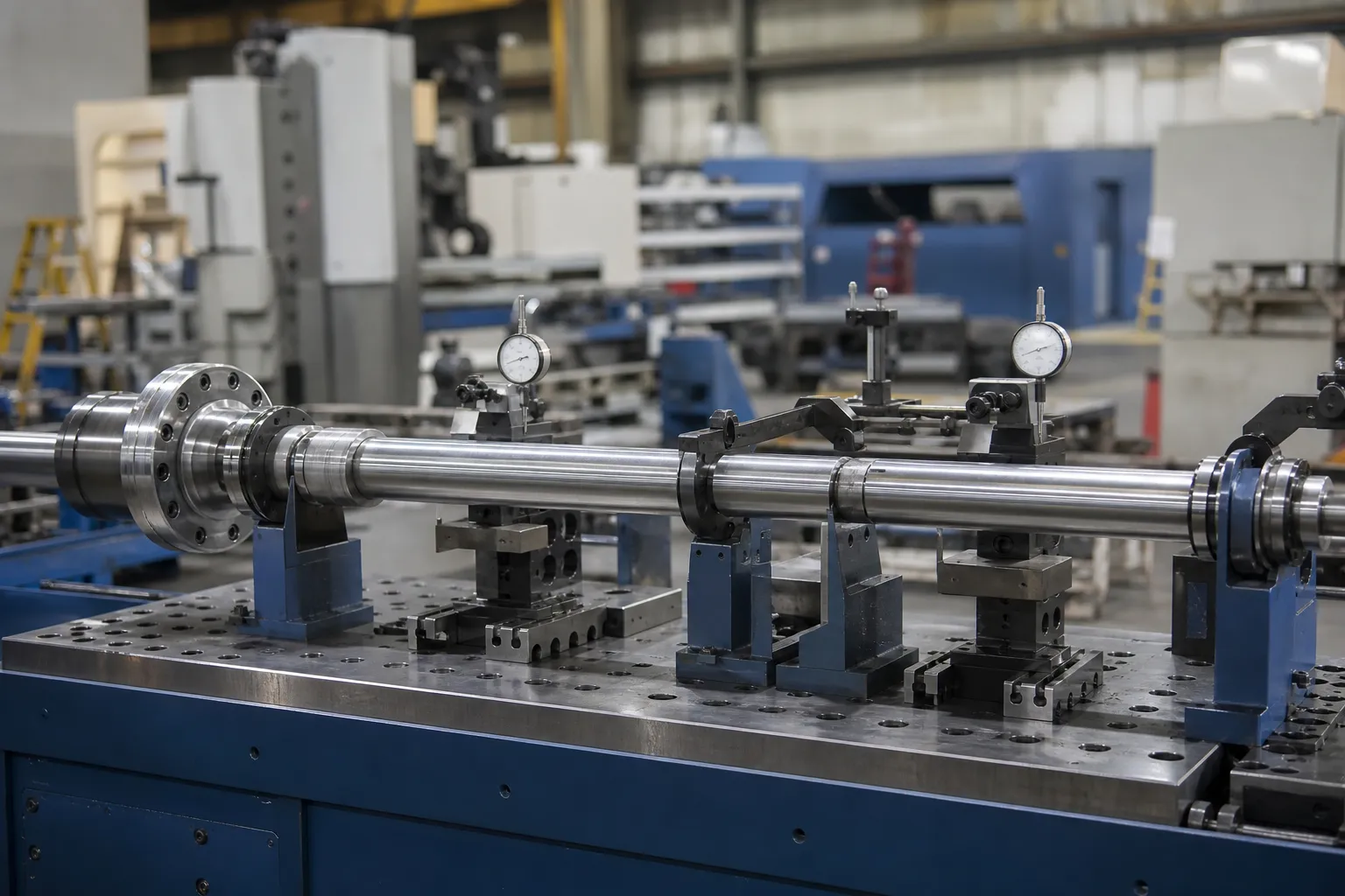
Margar tilfærslulestur geta breytt langskaftaskoðun úr einum toppi í villukort. Það gildi fer eftir fleiru en skynjaranum: styðja rúmfræði, datum sæti, rannsaka samband, snúningur/verðtrygging, samstillingu, umhverfisaðstæður og reiknireglan hefur öll áhrif á það sem tilkynnt er.

*Verkfræðihugtaksmynd. Það er ekki skynjaraforskrift, uppsett kerfi eða staðfest mæliniðurstaða.*
Skilgreindu einkenni áður en þú velur skynjara
Tilgreinið fyrst hvort viðtökueiginleikinn sé miðlínuréttleiki, staðbundin boga, runout miðað við datum, sniðfrávik eða önnur stýrð niðurstaða. Spennuskynjari eða tilfærsluspor er ekki sjálf krafa viðskiptavinarins. Skoðunaráætlunin verður að auðkenna viðmiðunareiginleika, styður, stöðvar, stefnur, span, útreikning, einingar, takmörk og í hvaða ástandi hluturinn er samþykktur.
| Frumefni | Spurning að loka |
|---|---|
| Dagsetning | Hvaða eiginleikar ákvarða viðmiðunarásinn eða yfirborðið? |
| Stuðningur | Afritar það ástand viðskiptavinar eða útgefinn hluta? |
| Rannsaka slóð | Eru snertipunktar virka yfirborð og varin gegn skemmdum? |
| Stöðvar | Fanga þeir þekkt beygjusvæði og lögun umbreytingar? |
| Snúningur/verðtrygging | Hvernig er stefnumörkun varðveitt á milli lestra? |
| Útreikningur | Hvernig er álestri breytt í stýrða eiginleikann? |
Fyrir datumstýringar, sjáðu Þrif á miðju gati á skafti og undirbúningur aðfanga og endurtekningarhæfni festinga og staðsetningarsæta.
How an LVDT Works, and Why Its Physics Matters
The linear variable differential transformer earns its place on production machinery through a short list of physical virtues. Inside the housing, a primary coil is excited with an alternating current, and two secondary coils sit either side of it; a ferromagnetic core, attached to the probe tip by a slim push rod, slides along the axis. With the core centered, the induced voltages in the two secondaries balance; displace the core and the balance tips in proportion to the movement. The electronics read the amplitude and phase of that imbalance and report displacement. Because the core never touches the coils, there is no friction or wear inside the sensor; because the coupling is inductive, the reading is largely indifferent to dust, oil mist and humidity that blind optical sensors; and because the moving mass is small, the tip can follow moderate surface motion faithfully. The trade-offs are equally physical: it needs signal conditioning and calibration against a reference, the raw output is relative rather than absolute, and the probe tip itself is a mechanical component with its own condition, force and wear story.
Where Errors Enter Between Probe and Number
Treating the chain as one system, as the section above demands, means knowing the specific doors through which error walks in. Thermal drift: the sensor body, the fixture and the part all expand and contract with temperature, and on a machine that warms through a shift, a morning zero and an afternoon reading are not the same event — hence reference checks on a master at intervals the procedure defines. Mounting: a probe on a long, unsupported bracket is a cantilever with its own compliance, and vibration or cable pull moves the whole assembly relative to the part, indistinguishable from part movement in the data. Dynamics: when the part or probe moves during scanning, the stylus mass and tip force set a speed limit beyond which the tip skips or lags, writing false features into the trace. Contact condition: tip wear flattens the intended radius and changes where the reading sits on a curved surface. None of these is exotic; each is controlled by written procedure — zero method, master check interval, scan speed, tip inspection — which is precisely what the validation framework above asks the system description to contain.
Meðhöndlaðu mælikeðjuna sem eitt kerfi
LVDT getur verið hentugur fyrir hlutfallslega tilfærslu, but the measured result also includes sensor mounting, fixture deflection, signal conditioning, tímasetningu, part seating and operator or automation behavior. Record every element in the chain so a later shift in the result can be investigated.

*Verkfræðihugtaksmynd. Fixture stiffness, sensor position and guarding require project-specific engineering.*
The controlled procedure should cover sensor identification, reference/master check, mounting condition, cable protection, zero method, sample orientation, support cleanliness, data acquisition settings and data retention. A repeated reading from an unstable fixture is not evidence of repeatability.
Synchronize Location, Orientation and Readings
Multipoint data is useful only when each value can be assigned to a known position and condition. Ef hluturinn snýst eða hreyfist, skilgreindu kóðara/vísitölu, stöðvahnit, akstursstefnu, dvalar- eða sýnatökuskilyrði, og hvað gerist ef merki vantar. Niðurstaðan ætti að varðveita hráu eða rekjanlega upprunagögnin sem þarf til að endurgera kortið.
Forðastu að túlka staðbundinn topp án þess að athuga sæti og snertingu. Endurtaktu próf, öfug stefnu þar sem við á og endurtekin grunnlínulesning getur greint hlutaeiginleika frá röngum vísbendingum.
Choosing Station Count and Placement
How many stations, and where, is a geometry question before it is a budget question. The error modes of slender parts are smooth in space: a bend is a low-frequency curve, so a modest number of stations — placed where the physics says the information lives — reconstructs it well, while doubling the count in uninformative positions buys data volume, not accuracy. Informative positions are predictable: mid-span between supports where a bow reaches its excursion; each stiffness transition on stepped parts, where peaks like to hide; immediately beside functional features whose relationship to the datum matters; and the free ends, which anchor the map. The failure mode of sparse placement is aliasing in its practical form — a short kink sitting between two stations contributes to neither reading cleanly, and a correction aimed at the reconstructed map presses in the wrong place. The honest way to close this risk is not infinite density but a validation: map a set of parts at high density once, confirm that the production station set reconstructs the same peaks and amplitudes, and document that comparison as the station-plan justification.
Turning the Map Into a Correction Decision
The map exists to drive action, and its action vocabulary has three entries: where to press, in which direction, and how hard to expect the part to respond. Peak position and direction come from comparing stations around the maximum; on a part rotating between stations, preserving angular indexing — the synchronization discipline above — is what converts separate readings into a vector, not a pile of magnitudes. Expected response comes from the stiffness story the map already tells: a peak on a heavy section needs a different correction plan than the same amplitude on a thin one, and peaks at stiffness transitions deserve the respect described for separating bend from roundness and setup effects before any press follows. What the map must not do is trigger correction on unverified signals: a localized reading that has not survived a reseat check is a hypothesis, not a peak. That guard rail — map, sannreyna, then correct, with released-state measurement closing the loop — is the same sequence that makes sjálfvirk skaftrétting converge in few strokes instead of many.
Tengjast við samþykki útgefinna hluta
Mælingar við klemmu eða leiðréttingu geta verið gagnlegar fyrir vinnslustjórnun, en það sannar ekki sjálfkrafa að losað skaftið uppfyllir kröfuna. Berðu línuaðferðina saman við viðurkennda losunarhlutaaðferð á dæmigerðum sýnum þvert á eðlilega breytileika. Sjáðu mæling á hlaðinni á móti slepptri réttstöðu fyrir mörkin.
*Verkfræðihugtaksmynd. Viðmiðunaraðferðin, stuðningur og samþykkisútreikningur verður að vera stjórnað af samþykktri gæðaáætlun.*
Fylgniáætlun ætti að skilgreina samsvarandi sýni, blindur samanburður þar sem raunhæft er, datum/stuðningsjafngildi, stöðu kvörðunar, hlutdrægni endurskoðun, endurtekningarhæfni/afritunarhæfni endurskoðun, leyfilegur mismunur, stigmögnun og breytingaeftirlitsreglur. Vísa til fylgni vélamælis á móti viðskiptavinamælis og gage R&R til að rétta línur.
Inntak sem þarf fyrir mælingarrannsókn
Gefðu upp teikningu og einkennandi skilgreiningu, núverandi skoðunaraðferð, hluta rúmfræði og datum eiginleika, efni/framleiðslustig, væntanlegar beygjustaðir, úrtaksþýði, umhverfisþvingunum, æskileg gagnaskrá og samþykkisaðferð viðskiptavina. Notaðu réttunarsýnispróf og staðfestingarleiðbeiningar að koma á réttarskrá, þá hafðu samband við StraighteningTech til umsóknarumræðna.
Nauðsynleg staðfesting fyrir kerfiskröfu
Any multi-point measurement claim needs a defined probe and datum setup, kvarðaðar tilvísanir, repeated or reseated readings on representative parts, and customer-gauge correlation. A generic machine capability is not a verified result.
Algengar spurningar
Does adding more measurement stations automatically improve accuracy?
Nei. Stations placed where the geometry has information — mid-span peaks, stiffness transitions, functional features, ends — improve the map. Stations added elsewhere add data volume and cost while leaving reconstruction essentially unchanged. Validate the chosen set once against a dense map and document the comparison.
Why do LVDT readings drift over a production shift?
Most often thermal: skynjari, fixture and part expand at different rates as the cell warms, shifting the zero. Mechanical causes come next — bracket compliance, cable pull, tip wear. The control is procedural: a defined zero method and reference-master checks at set intervals, with any shift beyond the procedure’s limit triggering investigation rather than quiet re-zeroing.
Can multipoint LVDT data replace final inspection?
Only through correlation. In-process multipoint data drives the correction loop; the acceptance decision belongs to the released-state method the customer recognizes. When the two have a documented correlation on representative parts, the line method gains standing — until then it is process control, not release.
Tengdar StraighteningTech Resources
Sjáðu hvernig sjálfvirk skaftrétting virkar, réttunarsýnispróf og samþykki og skaftbeinleiki vs runout vs TIR fyrir almenn eftirlitsmörk sem gilda áður en hæfiskröfur eru á LVDT fjölpunkta skaftmæling.
Multipoint measurement pays off at acceptance time – pair the FEITI gátlisti with the GD&T leiðbeiningar um staðfestingu á réttstöðu to agree measurement method and tolerance interpretation in one pass.