
Snúningsvísir getur innihaldið nokkur áhrif í einu. Það gæti endurspeglað ás vinnustykkisins, staðbundin hringleiki, sívalur form, datum samband, stuðnings sæti, innréttingarvilla, rannsaka uppsetningu eða truflun eiginleika. Að kalla hvern háan lestur „beygju“ getur leitt til rangrar leiðréttingaraðgerðar og getur skaðað hluta sem þarfnast mælingar eða vinnsluskoðunar.
Þessi handbók útskýrir hvernig á að greina merkið áður en ákvörðun er tekin um réttingu. Það kemur ekki á fót StraighteningTech mælikerfi, umburðarlyndi, upplausn skynjara, dagsetningaraðferð eða leiðréttingargetu. Stýrð teikning og skoðun viðskiptavina er krafist fyrir endanlegar ákvarðanir.

*Verkfræðihugtaksmynd. Það sýnir að snúningsmerki getur falið í sér formbreytingu; það er ekki mæliniðurstaða fyrir hluta viðskiptavinar eða áskilin skoðunaruppsetning.*
Nefndu einkenni áður en þú lest mælinn
Roundness lýsir þversniðsformsástandi. Ásbeygja lýsir staðbundinni leið tilvísunaráss. Runout er snúningsmæling miðað við viðmiðunaruppsetningu og getur innihaldið marga þátttakendur. Sameining, sammiðja og sívalning hafa einnig sérstakar skilgreiningar og skoðunarkröfur. Teikningin verður að tilgreina hvaða eiginleiki stjórnar samþykki.
| Merki eða einkenni | Greiningarspurning |
|---|---|
| Hringleiki / loping | Breytist staðbundinn radíus þegar hlutinn snýst? |
| Ásbeygja | Breytir viðmiðunarásinn stöðu eftir lengdinni? |
| Úthlaup | Hvaða datum, styður og rannsaka stöð búa til lesturinn? |
| Koax samband | Er verið að bera saman marga eiginleika við skilgreindan sameiginlegan ás? |
| Innréttingarmerki | Breytir niðurstaðan að endursetja eða breyta stuðningsstefnu? |
Sjáðu skaft beint, runout og TIR og coaxiality á móti runout fyrir skyld hugtök.
What a Rotating Trace Is Made Of
A probe reading taken while a part rotates is, mathematically, a mix of components that repeat once, twice, three times and more per revolution. Reading the mix is the core diagnostic skill. A once-per-rev component means the surface is, on average, further from the rotation axis on one side than the other — which is the signature of either an axis offset between the part’s reference geometry and the rotation axis, or of a bent axis displacing the section as a whole. A twice- or three-times-per-rev component means the section is oval or lobed: the local radius itself changes around the circumference, a form condition of the cross-section that no amount of axis correction removes. Higher-frequency content usually reflects surface texture, keyways and interrupted features, or vibration entering through the supports.
The decisive separation between the two once-per-rev causes is axial. A true bend displaces different stations by different amounts and often in different directions, so the once-per-rev component’s amplitude and phase change as the probe moves along the part. A pure eccentricity condition — centers offset, seat offset, chuck runout — produces a once-per-rev component that keeps the same phase and proportional amplitude at every station. One trace at one station cannot distinguish them; a short axial map routinely can. That is the reasoning behind the multi-station discipline above, and behind multipoint measurement arrangements that read several stations in one setup.
Where Lobing Comes From
Lobing is rarely random — it carries the fingerprint of the machining that produced the surface, which is what makes it diagnostic. Three-lobe out-of-roundness is the classic signature of parts ground on centerless machines, where the part floats between wheel, regulating wheel and blade and the geometry locks into a three-point stability condition. Even-lobe ovality traces back to opposing clamping or distortion relieved after machining — a thin sleeve released from a chuck, a part that relaxed after heat treatment. Odd lobing beyond three appears with certain workholding arrangements and with relapsing of interrupted cuts. Knowing the part’s process route therefore tells you what lobing to expect and whether an observed lobe count is a workpiece reality or an artifact of the current setup: a lobe count that changes when the part is reseated in different orientations is being generated by the setup, not the part.
Skoðaðu dagsetningu og uppsetningu fyrst
Áður en þú túlkar hlutann, staðfestu eiginleika miðstöðvarinnar, tímaritum eða öðrum tilvísunarflötum, stuðningsskilyrði, hreinlæti, rannsaka samband, snúningsaðferð og axial stöð. Skemmd miðstöð, burr, óhreint sæti, rangur stuðningur eða snerting rannsaka á rofnu yfirborði getur skapað augljóst úthlaup sem sýnir ekki ásbeygju.

*Verkfræðihugtaksmynd. Það sýnir eiginleika-meðvitaða dagbókarmælingu; raunveruleg viðmið, rannsakaspor og hyrndar grímur eru háðar stýrðu vinnustykkinu.*
Notaðu endurtekið/endurtekið athugun og berðu saman margar stöðvar. Ef ummerki breytist verulega eftir að uppsetningin er endurtekin, kanna innréttingu eða raungildi áður en leiðréttingarkrafti er beitt.
Berðu saman margar stöðvar og stefnur
Ásbeygja krefst venjulega áskorts. Staðbundin kringlótt eða loðinn getur birst á einni stöð en ekki annarri. Einn heildarvísitallestur á einum stað getur ekki sannað hvaða þátttakandi er ríkjandi. Taktu upp staðsetningu stöðvar, stefnumörkun, viðmiðunarskilyrði og ummerki eða útreiknuð niðurstöðu sem krafist er í samþykkisferlinu.
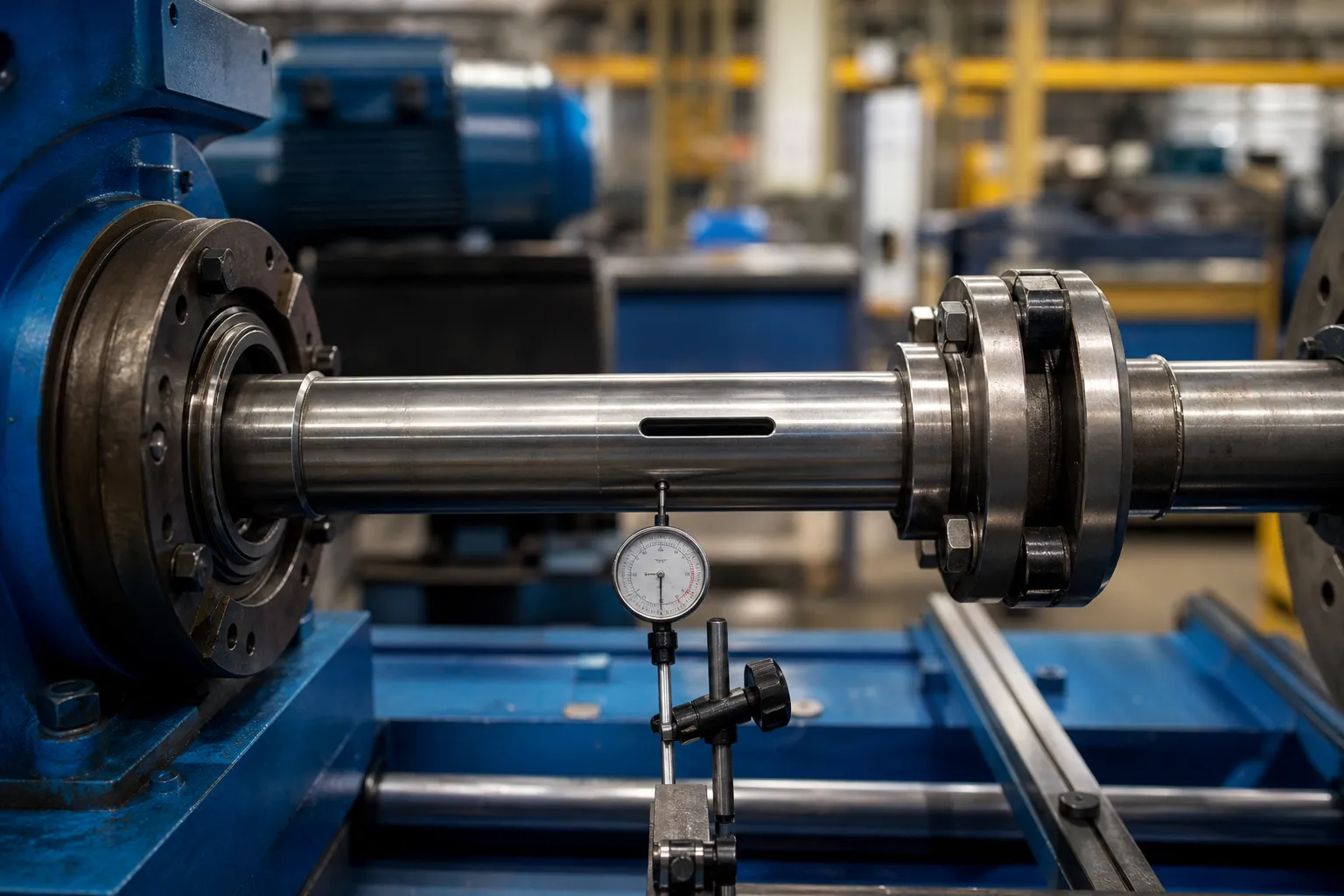
*Verkfræðihugtaksmynd. Það táknar spurningu um snúningsmælingu með mörgum eiginleikum, ekki viðurkenndur uppbúnaður eða niðurstaða um að merkið sem sést sé beygja.*
Separating Spindle Error From Part Error
On any rotating instrument, the reading contains the part’s geometry plus the rotation error of the instrument itself — spindle runout, bearing wander, support eccentricity. Precision metrology has standard separation techniques for this, and their logic is worth knowing even when the full apparatus is not available. Reversal methods measure the part in one orientation, then rotate the part exactly half a revolution relative to the fixture and measure again: part error keeps its sign in part coordinates while setup error keeps its sign in machine coordinates, so combining the two traces separates them. Multistep methods extend the same idea through a series of indexed orientations. On a production straightening machine, the practical descendants are simpler: reseating the part in a different clocking orientation and checking whether the trace rotates with the part or stays fixed in the machine tells most of the story, and comparing readings before and after swapping a support identifies which element contributes what.
These checks cost minutes and prevent the most expensive mistake on this page: correcting a bend that lives in the bench. They also make the eventual correlation to the customer gauge meaningful, because both sides of that comparison are then measuring parts rather than setups — the premise underlying gage R&R studies on straightening lines.
A Practical Diagnostic Sequence
The checks above assemble into a fixed order of operations that experienced lines follow before any correction decision. Fyrst, clean and inspect the seating features — centers, tímaritum, support vee blocks — for damage, burrs and debris, since the cheapest explanation is always the setup. Í öðru lagi, take a trace, reseat the part in the same orientation, and retrace: disagreement beyond the setup’s established repeatability stops the investigation at the fixture. Þriðja, reseat in a rotated orientation: a trace that follows the part is a part signal; one that stays fixed in the machine is a machine or fixture signal. Fourth, map at least three stations along the length and note how the once-per-rev component’s amplitude and phase behave: varying amplitude and rotating phase indicate bend; constant phase with proportional amplitude indicates eccentricity. Fifth, look at the lobe content in relation to the part’s machining history before believing any form conclusion. Only then choose the response — correction for confirmed axis bend within approved zones, or the alternative routes for everything else, with the released-state condition treated per loaded versus released measurement.
The sequence exists because each step filters a class of false positives that would otherwise survive to the next. Skipping ahead to correction is how parts get pressed for eccentricity fixtures, ovality and chucking artifacts — damage that no later measurement undoes.
Veldu svarið úr greiningunni
Ef sönnunargögnin styðja ástand ásbeygju og það eru viðurkennd snerti-/stuðningssvæði, hægt er að meta rétta leið með sýnishornsprófi. Ef merkið er aðallega kringlótt, truflað rúmfræði, datum mál, innréttingarvilla eða sérstakt eiginleikasamband, annað ferli eða endurskoðun skoðunar gæti þurft. Ekki nota réttu til að bæta upp mælivandamál.
Fyrir stýrða staðbundna leiðréttingu, sjáðu punkt-ýta réttingu. Fyrir fylgni við lokaskoðunaraðferð, see machine gauge versus customer gauge correlation.
Staðfestu með viðskiptavinamælinum
Sýnisáætlunin ætti að innihalda þekkt/viðmiðunarskilyrði þar sem þau eru tiltæk, endurtaka uppsetningu, margar stöðvar, mæling á losunarástandi, auðkenning á hluta og innréttingu, varðveisla hrágagna og fylgni við mælikvarða viðskiptavina. Í niðurstöðunni ætti að koma fram hvaða eiginleiki var metinn og hvaða óvissa eða uppsetningartakmarkanir eru eftir.
Algengar spurningar
Þýðir hátt TIR alltaf að skaftið sé bogið?
Nei. TIR getur innihaldið datum, kringlótt, fastur liður og aðrir þátttakendur. Greindu uppsetninguna og margar stöðvar fyrst.
Getur rétta rétt kringlótt?
Ekki sem almenn niðurstaða. Hringleiki er annað rúmfræðilegt ástand og gæti þurft annað ferli eða skoðunarleið.
Af hverju að endurtaka uppsetninguna?
Endurlestur eftir endursetningu hjálpar til við að greina merki vinnustykkis frá stuðningi, viðmiðunarpunktur eða afbrigði af innréttingum.
What does a three-lobed trace usually indicate?
Most often, a surface produced by centerless grinding, where the three-point contact of wheel, regulating wheel and blade locks the section into a three-lobe form condition. It is a cross-sectional form issue, not an axis issue, and it should be verified against the part’s machining history before any response is chosen.
How can I tell eccentricity from bend with one probe?
Move the probe along the part and watch the once-per-rev component. Bend shows varying amplitude and shifting phase between stations; eccentricity keeps the same phase and proportional amplitude everywhere. If the probe cannot move, mapping several stations with a moved setup achieves the same separation at the cost of reseating discipline.
Does reseating the part in a different orientation really separate machine error?
Já, in its simplest form. Part error rotates with the part; machine and fixture error stay fixed in machine coordinates. Comparing traces at two clockings shows which class dominates the reading. Formal reversal and multistep methods refine the same principle when numbers, not just classification, eru nauðsynlegar.