
A hajtótengely egyszerű hosszú csőnek tűnhet, de egyengetési problémáját a teljes nyomatékátviteli geometria határozza meg. A csőtest, hegesztett végek, igák, karimák, az univerzális csuklós interfészeknek és a középső csapágyaknak egy vonalban kell maradniuk anélkül, hogy összenyomnák az üreges szakaszt, vagy ne keverjék össze a geometriai kifutást a dinamikus kiegyensúlyozatlansággal.
A megbízható hajtótengely-egyenesítő megoldás tehát az alkatrészrajzzal kezdődik, szerelési szakasz és átvételi mód. Meg kell határoznia a funkcionális referenciatengelyt, szöges tájolás, mérőállomások, védett területek, megengedett korrekciós zónák, valamint a kiegyenesítés és a kiegyenlítési folyamat közötti kapcsolat.
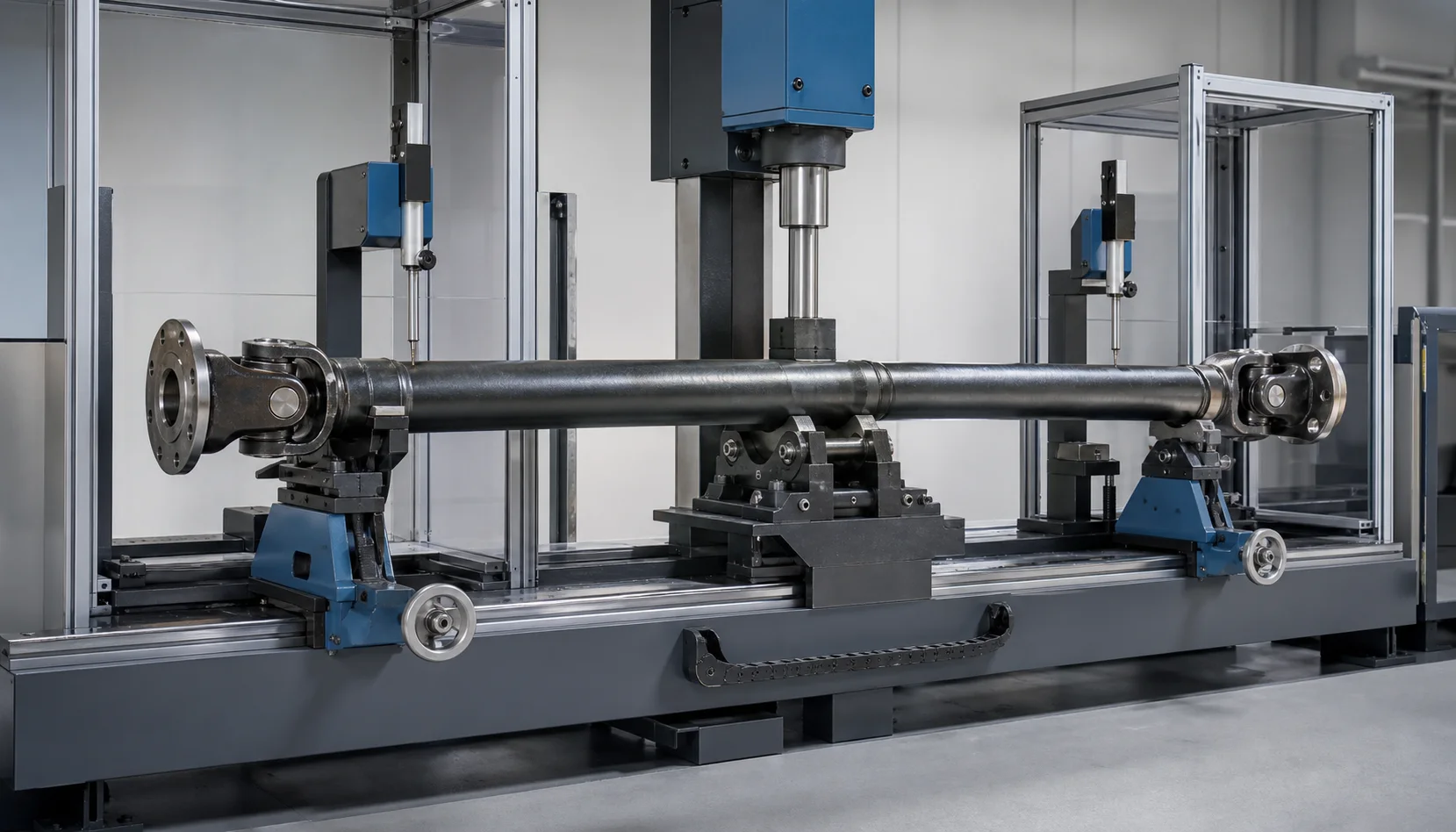
Ez egy mérnöki koncepció illusztráció, nem ügyféloldali fénykép. A gép tényleges fesztávja, őrzés, szerszámozás, Az érzékelők és a korrekciós kapacitás a hajtótengely családtól és a mintavizsgálatoktól függ.
Miért van szükség a hajtótengelyekhez speciális egyengetési megoldásra?
| Kardántengely funkció | Egyengető kockázat | Projektreakció |
|---|---|---|
| Üreges hegesztett cső | A helyi betöltés horpadásokat okozhat, ovalitás vagy összeomlás | Használjon csőspecifikus támasztékokat és korrekciós szerszámokat |
| Vég igák, karimák vagy tengelykapcsolók | A közönséges tokmányok helytelenül ülhetnek fel, vagy károsíthatják a felületeket | Keresse meg a jóváhagyott funkcionális jellemzőket megismételhető szögpozicionálással |
| Egy vagy több darabból álló konstrukció | Minden szakasznak eltérő referencia- és támogatási feltétele lehet | Rögzítse a pontos összeszerelési konfigurációt és a mérési útvonalat |
| Hegesztett kötések | A hegesztési varrat torzulása eltolhatja a cső tengelyét és végét | Mérés rajzalapú állomásokon a megfelelő hegesztési szakasz előtt és után |
| Univerzális csuklós interfészek | Az ízületi hézag és a csukló eltakarhatja a valódi hivatkozást | Határozza meg, hogy az illesztések be vannak-e szerelve, bezárt, mesterekkel helyettesítve vagy kizárva |
| Hosszú fesztáv | Az önsúly és a támasztó hely megváltoztathatja a mért görbét | Érvényesítse a támogatási koordinátákat és a korrelációt az ügyfélmérővel |
| Nagy sebességű működés | A kifutás és a tömeg kiegyensúlyozatlansága egyaránt rezgést okozhat | A geometriai egyengetést és a dinamikus kiegyensúlyozást külön vezérlőként kezelje |
| Szögfázis követelmény | A megfelelő lefutás nem garantálja a megfelelő igából-igába fázist | A fázis mérése vagy mechanikai megőrzése független jellemzőként |
A mérnöki cél nem csupán az indikátor mozgásának csökkentése egy kényelmes csőhelyen. Ennek célja a megadott geometria szabályozása a cső megőrzése mellett, hegesztett zónák, az ízületi interfészek és a lefelé irányuló egyensúlyi állapot.
Határozza meg, hogy melyik „hajtótengely” tartozik a hatókörbe
Hajtótengely, propeller tengely, A kardántengelyt és a sebességváltó tengelyt néha felcserélhetően használják. A javaslatban az általános nevet egy pontos alkatrészcsaláddal kell helyettesíteni.
| Rész család | Tipikus konstrukció | Az egyenesítés fő kérdése |
|---|---|---|
| Egyrészes gépkocsi propeller tengely | Üreges cső hegesztett jármokkal vagy karimákkal | A cső kifutása, végigazítás, fázis és egyensúly sorrendje |
| Több darabból álló propeller tengely | Két vagy több cső alakú rész középső csapágyakkal | Szakasz hivatkozások, a középső csapágy alappontja és az összeszerelt viselkedés |
| Ipari kardántengely | Cső alakú vagy tömör test csuklós csatlakozókkal | Csatolás helye, teleszkópos metszet és működési szög követelményei |
| Csupasz hajtótengely cső | Cső a végső végösszeszerelés előtt | A cső egyenessége, ovalitás és hegesztés-előkészítési ráhagyás |
| Összeszerelt hajtótengely | Cső, igák, ízületek, karimák és egyensúlysúlyok | Teljes összeszerelés lefutása, fázis és végső mérleg érvényesítése |
A benyújtott rajzon és mintán fel kell tüntetni, hogy a céltárgy csupasz cső-e, egy hegesztett tengely, csuklós szerelvény vagy kész kiegyensúlyozott alkatrész. Az egyik szakaszban érvényesített folyamat nem vihető át automatikusan a másikba.
Tartsa meg a hajtótengelyt, A tengelytengely és a kormánytengely tartalma külön
Ezek az alkatrészek mind mozgást vagy nyomatékot közvetítenek, de geometriájuk és elfogadási logikájuk nem felcserélhető.
| Összetevő | Közös geometria | Dedikált tartalomfókusz |
|---|---|---|
| Hajtás / propeller tengely | Hosszú, üreges cső hegesztett jármokkal, karimák vagy tengelykapcsolók | Csővédelem, végigazítás, fázis, kifutási és egyensúlyi határ |
| Tengely / féltengely | Általában tömör vagy helyileg üreges lépcsős tengely bordával és esetleges kerékkarimával | Folyóirat, spline, tengely-test és karima kapcsolat |
| Kormánytengely | Kisebb kormányoszlop sebességváltó tag, gyakran teleszkópos vagy csuklós | A kormányfelület geometriája, összecsukható/teleszkópos jellemzők és biztonsági követelmények |
A régebbi Autóalkatrészek és Kormánytengelyek oldalak navigációs rétegek maradhatnak. Ez az oldal megválaszolja a hajtótengely-specifikus gyártási és felszerelési kérdéseket anélkül, hogy minden autótengelyt ugyanazon munkadarabként kezelne.
Fagyassza le a gyártási és javítási szakaszt
Az előnyben részesített egyengetési útvonal az akna állapotával változik.
Csupasz cső a hegesztés vége előtt
A csupasz cső egyszerűbb hozzáférést biztosít, de a későbbi hegesztés új torzulást okozhat. A kiegyenesítés ebben a szakaszban hasznos lehet a bejövő cső ellenőrzéséhez vagy előkészítéséhez, mégsem helyettesíti a hegesztés utáni mérést.
Hegesztett tengely a végső megmunkálás előtt
Vég igák, a karimák vagy csonkok már csatlakoztatva vannak, így a rendszer ki tudja értékelni a csőhöz való viszonyukat. A fennmaradó megmunkálási ráhagyást és hőbevitelt a tervbe kell foglalni.
Kész tengely a kiegyensúlyozás előtt
Ez a szakasz meghatározhatja azt a geometriai állapotot, amely belép a kiegyensúlyozó gépbe. Felületvédelem, a közös kezelési és korrekciós határok szigorúbbá válnak, mert már több értéket adtak az alkatrészhez.
Korábban kiegyensúlyozott tengely
Ha vannak egyensúlysúlyok, a préselés megváltoztathatja a cső geometriáját, súlypozíciót vagy a mért egyensúlyi állapotot. Az alkatrésznek a kiegyenlítés után vissza kell térnie a jóváhagyott kiegyensúlyozási ellenőrzéshez, hacsak az ügyfél folyamata kifejezetten nem bizonyítja az ellenkezőjét.
A tengely újjáépítése vagy javítása
Viselet, horpadás, sérült ízületek, a helytelen hegesztések és a korábbi korrekciós kísérletek alkalmatlanná tehetik az egyengetést. Az ellenőrzési tervnek tartalmaznia kell az elutasítási szabályokat; az automata egyengető nem helyettesíti a szerkezeti javítási értékelést.
Határozza meg a szabályozott karakterisztikát
Ne használja az „egyenes tengelyt” teljes átvételi követelményként. A rajz külön vezérelhető:
- cső vagy tengelytengely egyenessége;
- körkörös kifutás vagy teljes kifutás meghatározott metróállomásokon;
- elfogynak a végpilóták, folyóiratok, karimás felületek vagy tengelykapcsoló jellemzők;
- a végjellemzők koncentrikussága vagy koaxiális kapcsolata;
- járom vagy karima szögfázis;
- cső külső átmérője és oválissága;
- a hegesztéssel kapcsolatos geometria és a megengedett korrekciós zónák;
- a teljes forgó egység maradék kiegyensúlyozatlansága;
- funkcionális rezgés vagy zaj a végső rendszertesztben.
A kiegyenesítés befolyásolhatja a geometriai kifutást, de nem korrigálja automatikusan a fázishibát, ízületi kopás, karima-felület hiba, hegesztési minőség vagy tömegkiegyensúlyozatlanság. Tekintse át Tengely egyenesség vs kifutás vs TIR mielőtt egy rajzi követelményt indikátorbeállítássá konvertálna.
Építse fel a mérést a funkcionális referencia alapján
A referenciatengelynek meg kell egyeznie a rajzzal, vagy dokumentált korrelációval kell rendelkeznie a vevői mérőeszközzel. A lehetséges referencia megvalósítások közé tartozik:
Végpilotok vagy karimaregiszterek
A precíziós pilóták vagy regiszterek reprodukálhatják a beépített forgástengelyt, ha formájuk és állapotuk megfelelő. A helymeghatározó felületeknek tisztáknak kell lenniük, sértetlen és következetesen ül.
Univerzális csuklós illesztőfelületek
A dedikált mesterek vagy tokmányok a csatlakozási felületről találhatnak. Engedélyek, a csapágypohár állapotát és az ízületi csuklót ellenőrizni kell, hogy a rögzítés ne hozzon létre hamis kifutást.
Csapágy vagy középső csapágy naplók
Több darabból álló tengelyen, a középső csapágycsap a funkcionális tartórendszer része lehet. A mérési tervben fel kell tüntetni, hogy nullapontról van-e szó, ellenőrzött jellemző vagy csak ideiglenes géptámogatás.
Matematikai tengely több szolgáltatásból
Az érzékelők képesek mérni a kiválasztott pilótákat, naplókat vagy metróállomásokat, és számítson ki egy kapcsolódó referenciatengelyt. Az algoritmus, állomás koordinátái, a szűrési és kiugró szabályokat a jóváhagyott szelvényhez képest kell érvényesíteni.
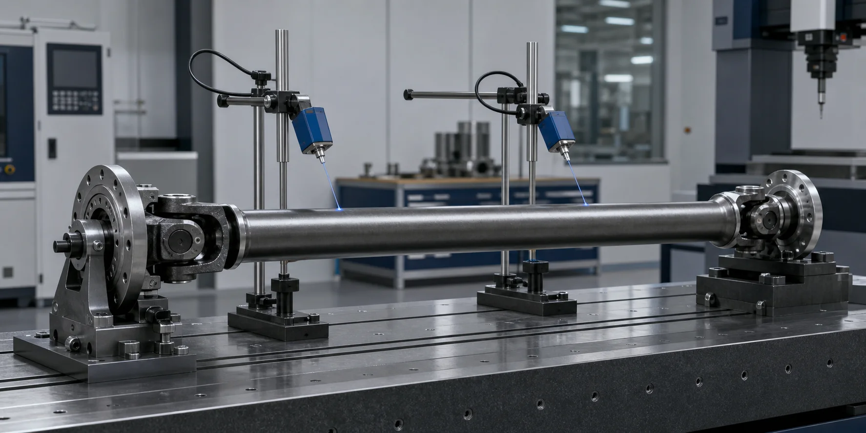
Ez a mérnöki koncepció illusztráció az érintésmentes cső mérését és a végberendezés tájolását mutatja. Nem ír elő minden projekthez konkrét szenzortechnológiát.
Ne olvassa el a szabálytalan csőfelületet valódi tengelyként
Egy hegesztett vagy formázott csőnek helyi felületi eltérései lehetnek, varrat hatások, bevonat, hegesztési fröcskölés vagy ovális. Az érzékelő leolvasása egy kerületi sávon ezért egyaránt tartalmazhat középvonali mozgást és felületforma hibát.
| Mérési változó | Lehetséges hamis jel | Ellenőrzési módszer |
|---|---|---|
| Cső felületi textúrája | Rövid periódusú elmozdulásváltozás | Válasszon ki egy jóváhagyott számot, és érvényesítse a szűrést |
| Ovalitás | Két lebenyű jel, amely a kifutáshoz hasonlít | Mérje meg az átmérőt/formát külön, vagy használjon több érzékelési irányt |
| Hegesztési varrat | Lokális csúcs vagy reflexiós változás | Határozza meg a varráskezelést és az érzékelő alkalmasságát |
| Bevonat vagy szennyeződés | Instabil érintkezés vagy optikai válasz | Állítson be tisztasági és felületi állapotra vonatkozó szabályokat |
| Közös hézag | A végelem csőhajlítás nélkül mozog | Zár, előtöltés, master vagy zárja ki a csatlakozást az érvényesített módon |
| Szerelvényes ülés | Az újbóli rögzítés megváltoztatja a jelzett csúcspontot | Végezzen ismételt terhelési és újraülési vizsgálatokat |
| Hosszú fesztávú lehajlás | Tartásfüggő látszólagos görbület | A támaszpontok és a tájolás rögzítése |
A mérőrendszernek több axiális állomást kell feltérképeznie, ne következtessen az egész tengelyre egy felezőpontból. Meg kell őriznie a nyers vagy összesített állomásadatokat is a folyamatok felülvizsgálatához, ha nyomon követhetőségre van szükség.
Tartójárom és karima fázis
A fázisozás a végjellemzők közötti szögkapcsolatot írja le, főleg igákat. Ez nem ugyanaz, mint az egyenesség, és nem korrigálják pusztán azért, mert a cső kifutása csökken.
A projektnek meg kell határoznia:
- a nulla szöget létrehozó jellemző;
- a megengedett fázisviszony és tolerancia;
- hogyan helyezkednek el az egyes végek közös játék nélkül;
- hogy a gép csak megőrzi-e a fázist, vagy ellenőrzi is azt;
- hogy minden szöghelyzetben megengedett-e a préselés;
- hogyan kezelik a sikertelen fázisellenőrzést;
- hogy a fázist egyengetés előtt ellenőrizzük-e, egyengetés után vagy mindkét szakaszban.
Szögletes lokátor, látórendszer vagy jellemző-specifikus szonda megfelelő lehet, de a kiválasztás a pontos igától függ, karima, gyűrű vagy tengelykapcsoló geometriája. A gép soha nem forgathatja el a tengelyt olyan korrekciós helyzetbe, amely törékeny elemet okoz, hegesztési vagy egyensúlyozási súlyt egy nem biztonságos terhelési útvonalon.
Védje az üreges csövet az összeomlástól és a benyomódástól
A csővédelem számos kardántengely meghatározó szerszámozási problémája. A keskeny támasztékok vagy a kis nyomóorr helyileg elfogadható kifutási eredményt hozhat létre, miközben tartósan károsítja a keresztmetszetet.
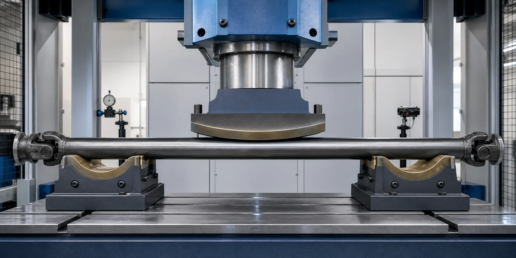
Ez a mérnöki koncepció illusztráció széles, megfelelő érintkezést mutat. A nyereg tényleges sugara, bélés, érintkezési hossz és erőkorlát reprezentatív mintaellenőrzést igényel.
Megfelelő támasztékok
A széles nyergek nagyobb ívben oszthatják el a reakcióerőt. Az átmérőjük megegyezik, bélésanyag, a perem sugarát és tisztaságát a csőfelülethez és a terheléshez kell megválasztani.
Borítékolás-javító szerszámok
A rádiuszos vagy beborító préspapucs csökkentheti a helyi érintkezési feszültséget a keskeny lyukasztóhoz képest. Ennek továbbra is elegendő szabályozott hajlítónyomatékot kell biztosítania a kiválasztott fesztávon.
Belső támogatás, amikor szükséges
Egyes csőcsaládokhoz tüskére lehet szükség, dugót vagy más belső támaszt. A belső szerszámok hozzáférést biztosítanak, átállási és jelölési kockázatok, ezért csak akkor szabad használni, ha a mintavizsgálat igazolja annak szükségességét.
Ovalitás és felület ellenőrzése
A korrekció utáni átvételnek tartalmaznia kell a megadott csőátmérőt, ovális, horpadás és felület kritériumai. Egy tengely nem elfogadható pusztán azért, mert a radiális indikátor értéke javult.
Hegesztési varratok térképe, Kiegyensúlyozott súlyok és nyomásmentes zónák
A rajznak és a minta áttekintésnek meg kell határoznia az összes olyan régiót, amelyet nem lehet betölteni vagy elérni:
- kerületi vagy hosszanti varratok;
- hőhatás övezetek projektspecifikus korlátozásokkal;
- egyensúlysúlyok és rögzítési zónáik;
- vékony átmenetek jármák vagy karimák közelében;
- zsírszerelvények, tömítések és csatlakozási vasalat;
- spline, szálak, pilóták és kész csapágyfelületek;
- címkéket, bevonatok vagy korrózióvédő területek;
- horpadások, repedések vagy előzetes javítási zónák, amelyek visszautasítást igényelnek.
A receptnek ezeket a jellemzőket axiális és szögletes zónákká kell alakítania. Ha a biztonságos korrekciós ablak túl kicsi, a helyes döntés lehet a gyártási sorrend megváltoztatása vagy az alkatrész elutasítása, nem pedig a nem biztonságos korrekció kényszerítése.
Ajánlott zárt hurkú kiegyenesítő eljárás
1. Határozza meg az alkatrész és a folyamat szakaszát
Válassza ki az érvényes receptet egy cikkszámból, vonalkód vagy adatmátrix. Ellenőrizze, hogy az alkatrész csupasz cső-e, hegesztett tengely, összeszerelt tengely vagy javított alkatrész.
2. Vizsgálja meg és töltse be biztonságosan
Ellenőrizze, hogy vannak-e látható horpadások, sérült ízületek, laza súlyok, súlyos hegesztési hibák vagy egyéb visszautasítási körülmények. Terhelje meg a tengelyt anélkül, hogy a jármákat ütné, karimák vagy csőfelület.
3. Keresse meg a funkcionális pontpontokat és a szögjellemzőt
Helyezze fel a jóváhagyott végcsatlakozókat, és állítsa be a fázisreferenciát. Elforgatás vagy mérés előtt észlelje a hiányos illeszkedést.
4. Több tengelyirányú állomás mérése
Ellenőrzött körülmények között forogjon, és készítsen egy kanyar/kifutási térképet a megadott állomásokról. A validált módszerrel válassza el az ismert felületforma hatásokat a középvonali mozgástól.
5. Válasszon egy biztonságos korrekciós zónát
A szabályozási logika egyesíti az eltérési térképet a csőmerevséggel, támogatás fesztáv, hegesztési helyek, véggeometria, fázistájolás és minden nyomásmentes zóna.
6. Alkalmazzon szabályozott túlhajlítást
Mozgassa a széles támasztékokat és a megfelelő korrekciós szerszámokat a jóváhagyott koordinátákhoz. Alkalmazzon korlátozott korrekciós löketet vagy erőt az érvényesített modellnek megfelelően.
7. Elengedés és újramérés
Az eredmény megítélése előtt távolítsa el a korrekciós terhelést. Mérje meg újra a megfelelő állomásokat, és frissítse a rugós modellt. Rugós kiegyenlítés a tengelyegyenesítésben megmagyarázza, hogy miért nem a terhelt elmozdulás a végső geometria.
8. Független jellemzők ellenőrzése
Erősítse meg a szükséges kifutó állomásokat, fázis, végpont geometriája, cső ovális, a felület állapota és a hegesztési zóna meghatározott ellenőrzése. Vezesse a tengelyt a kiegyensúlyozáshoz vagy a végső összeszereléshez a szabályozási tervben meghatározottak szerint.
9. Felvétel és kirakás
Alkatrész azonosítója, recept átdolgozása, előtt/után értékek, korrekciós előzmények, riasztások és elhelyezés, ha nyomon követhetőség szükséges. Tehermentesítse a hézag helyzetének megváltoztatása vagy a kész felületek károsodása nélkül.
Az egyenesítés és a dinamikus kiegyensúlyozás különböző folyamatok
A geometriai kifutás azt írja le, hogy a megvalósított felület vagy jellemző hogyan mozog a referenciahoz képest elforgatás közben. A dinamikus kiegyensúlyozatlanság a tömegeloszlást és a szerelvény forgása során keletkező erőket/nyomatékokat írja le. A hajtótengely lehet geometriailag egyenes, de kiegyensúlyozatlan, vagy alacsony a maradék kiegyensúlyozatlansága, miközben továbbra is elfogadhatatlan kifutást mutat.
| Folyamat | Elsődleges bemenet | Tipikus korrekció | Mit nem bizonyít |
|---|---|---|---|
| Egyenesítés | Hajlítási/kifutási térkép és jóváhagyott geometriai adatok | Ellenőrzött hajlítás biztonságos helyeken | A maradék egyensúlyhiány a tűréshatáron belül van |
| Fázisellenőrzés | Meghatározott végjellemzők szögviszonya | Összeállítás/indexelés javítása vagy elutasítása | A cső középvonala és tömegeloszlása elfogadható |
| Dinamikus egyensúlyozás | Forgási egyensúlyhiány nagysága és szöge egy vagy több síkban | Hozzáadás, távolítsa el vagy helyezze át a tömeget jóváhagyott módszerrel | Tengely geometriája, a hegesztési varrat integritása vagy fázisa elfogadható |
Sok kész tengelyhez, a védhető út a túlzott kifutás korrigálása a végső kiegyensúlyozás előtt, majd az egyensúly ellenőrzése bármely későbbi geometriai korrekció után. A pontos sorrendnek követnie kell az ügyfél rajzát, mérleg specifikáció és validált gyártási út. Az egyengetés nem helyettesíti a kiegyensúlyozó gépet.
Point Press Straightening vagy Roller Straightening?
A kész kardántengely általában különálló jármákat tartalmaz, karimák, hegesztési varratok és védett zónák. Ezek a jellemzők gyakran előnyben részesítik az ellenőrzött pontnyomás-korrekciót dedikált támasztékokkal, mivel a gép kiválasztott tengelyirányú és szögletes helyeket tud megcélozni..
A görgős egyengetés releváns lehet a megfelelő csupasz állandó keresztmetszetű cső- vagy rúdanyag esetében, de nem szabad azt feltételezni, hogy kész csuklós tengelyre alkalmas. Tekintse át Press Straightening vs Roller Straightening a folyamatcsalád kiválasztása előtt.
Javasolt hajtótengely-egyenesítő cella
| Cell Funkció | Projekt-specifikus konfiguráció |
|---|---|
| Alkatrészkezelés | Kézikönyv, asszisztált vagy automatizált rakodás tömeg alapján, hossza és térfogata |
| Befejezési hely | Dedikált karima, pilóta, járom vagy tengelykapcsoló szerszámok ülésérzékeléssel |
| Szögletes pozicionálás | Mechanikus lokátor, kódoló, látás- vagy funkcióérzékelő az érvényesítés szerint |
| Forgás | Ellenőrzött alacsony sebességű indexelés csukló/szerelvény biztonsági ellenőrzésekkel |
| Mérés | Érintkezési vagy érintésmentes érzékelők rajzalapú állomásokon |
| Támogatás | Állítható széles nyergek a cső átmérőjéhez és a korrekciós terheléshez igazodva |
| Javítás | Szervo-elektromos vagy hidraulikus présegység erő/elmozdulás figyeléssel |
| Recept ellenőrzés | Részcsaládi paraméterek, védett zónák és a felülvizsgálatok kezelése |
| Minőségi ellenőrzések | Kifutás, fázis, csőforma, felületi és szükséges végelem-ellenőrzések |
| Nyomon követhetőség | Előtte/utána adatok, korrekciós előzmények, riasztások és elhelyezés |
| Biztonság | Őrzés, reteszelések és kockázatértékelés az alkatrészforgáshoz és a tárolt energiához |
A gép kapacitása nem választható csak a teljes tengelyhosszból. A cső átmérője és falvastagsága, anyag, hozam viselkedés, támogatás fesztáv, vég tömege, a bejövő deformáció és a biztonságos érintkezési terület egyaránt befolyásolja a szükséges erőt, löket és szerszámozás.
Mintavizsgálat és elfogadás
A gépekre és szerszámokra vonatkozó végleges kötelezettségvállalás előtt reprezentatív mintavizsgálatra van szükség. A mintakészletnek fednie kell:
- minimális és maximális csőátmérő, falvastagság és hossz;
- egy- és többrészes változatok, ha mindkettő a hatálya alá tartozik;
- minden releváns iga, karima és tengelykapcsoló interfészek;
- tényleges anyag, hőkezelés, hegesztési varrat állapota és bevonata;
- reális bejövő kifutási nagyságrend és kanyarhelyek;
- adott esetben jóváhagyott mérlegsúllyal rendelkező alkatrészek;
- normál és nehéz fázisorientáció;
- ügyfél által jóváhagyott mérési és mérleg korrelációs minták.
Az átvételi tervnek meg kell határoznia a bejövő elosztást, céljellemzők, szelvény megállapodás, ismétlődő terhelés ismételhetősége, felületi és ovális határok, megengedett korrekciók száma, repedés- vagy hegesztésvizsgálati követelmények, ciklus-idő határ, nyomon követhetőség és a nem megfelelő alkatrészek elhelyezése.
Használja a Egyenesítő minta vizsgálati és elfogadási útmutató megosztott protokoll felépítésére, mielőtt garantált eredményt kérne.
A hajtótengely-javaslathoz szükséges információk
Egy automatikus hajtótengely-egyenesítő megoldás értékeléséhez, nyújtani:
- 2D rajz és, amikor elérhető, 3D modell;
- alkatrésznevek és egyrészes/több darabból álló konstrukció;
- teljes hossza, cső külső átmérője és falvastagsága;
- anyag, hőkezelés, bevonattal és hegesztéssel kapcsolatos információk;
- iga, karima, tengelykapcsoló és középső csapágy részletei;
- összeszerelési szakasz, amelyben az egyengetés megtörténik;
- rajz nullapontok és minden ellenőrzött kifutási/egyenességi állomás;
- fázisigény és referencia jellemzők;
- bejövő deformáció eloszlás, nemcsak a legrosszabb minta;
- megengedett támogatási és korrekciós zónák;
- védett felületek, hegesztési varratok, súlyok és nyomásmentes zónák;
- ovális, horpadás, felület és repedés átvételi szabályok;
- egyensúlyozó szakasz, specifikáció és a szükséges folyamatok sorrendje;
- modell mix, tétel mérete, cél átviteli sebesség és betöltési módszer;
- nyomon követhetőség, adatexportálási és vonalintegrációs követelmények;
- képviselő jó, tipikus és nehéz minták;
- ügyfélmérő vagy mérő-korrelációs módszer.
Ezt az információt használjuk a mérési referencia konfigurálásához, vége szerszámozás, szögletes pozicionálás, támogatás fesztáv, csővédő szerszámok, korrekciós modell és érvényesítési terv. Ahol a bizonyítékok hiányosak, a javaslatnak feltételesnek kell maradnia mindaddig, amíg a mintavizsgálat be nem zárja a rést.
GYIK
Egy hajtótengely-egyenesítő is kiegyensúlyozza a tengelyt?
Nem automatikusan. Az egyengetés a megadott geometriát szabályozza; a kiegyensúlyozás méri és korrigálja a tömegeloszlást forgás közben. Egy termelő cella mindkét műveletet összekapcsolhatja, de mindegyiknek saját mérési rendszerre van szüksége, korrekciós módszer és elfogadási kritériumok.
Miért kell a kimerülést korrigálni a végső kiegyenlítés előtt??
A túlzott geometriai kifutás megzavarhatja az ismételhető támogatást és a forgási viselkedést. Ha először kijavítja, stabilabb bemenetet biztosíthat a kiegyensúlyozáshoz. Viszont, a jóváhagyott megrendelést pontosan a tengelyre kell érvényesíteni, szerszám- és mérlegspecifikáció.
Kiegyenesíthet-e a gép egy kardáncsuklóval felszerelt tengelyt?
Ez lehetséges dedikált szerszámokkal és ellenőrzött csatlakozási állapottal. Az ízületi hézag és a csukló téves méréseket eredményezhet, így a projektnek meg kell határoznia az illesztések elhelyezkedését, zárva vagy mesterek által képviselve.
Hogyan lehet megakadályozni, hogy egy üreges cső összetörjön??
A megoldás csőspecifikus támogatási és korrekciós koncepciókat alkalmaz, mint például a széles, megfelelő nyergek, sugaras vagy burkoló préscipők, erő/löket határok és, amikor indokolt, belső támogatás. A tényleges tervezést reprezentatív mintákon kell igazolni, és ellenőrizni kell az ovális és felületi sérülések szempontjából.
A cső elfogadható kifutása a megfelelő járomfázisnak bizonyul??
Nem. A kifutás és a fázis független jellemzők. A fázisreferenciát és a tűréshatárt külön kell mérni vagy mechanikusan megőrizni.
Egy gép képes-e különböző hosszúságú és átmérőjű hajtótengelyeket kezelni?
Igen, amikor a munkadarab-családok az érvényesített erőn belülre esnek, span, forgás, érzékelő és szerszámburok. Az állítható állomások és a tárolt receptek támogatják a modellváltást, de a végfelületek és a csőátmérők speciális szerszámot igényelhetnek.
Egy korábban kiegyensúlyozott hajtótengely kiegyenesíthető?
Potenciálisan, de a korrekció befolyásolhatja az egyensúlyi állapotot vagy a mérlegsúlyokat. Az alkatrészt a kiegyenesítés után vissza kell küldeni a jóváhagyott kiegyensúlyozási ellenőrzésre, kivéve, ha az ügyfélfolyamat kifejezetten más útvonalat hoz létre.
Mi a leggyorsabb módja annak, hogy hasznos ajánlatot kapjon?
Evaluating drive shaft straightening for a production line? Kezdje a gépválasztási útmutató tengelyekhez, csövek és profilok és a egyengető gépek árbontása mielőtt árajánlatot kér.
Küldje el a rajzot, cső méretei, szerelési szakasz, kifutási és fáziskövetelmények, egyensúlyi sorrend, védett zónák, bejövő alkatrészadatok és reprezentatív minták. Egy egyértelmű mérési referencia értékesebb, mint egy általános kérés a gép pontosságára vonatkozóan.
Építse meg a megoldást a teljes forgó egységből
A hajtótengely-egyengető megoldásnak jobban kell védenie, mint a cső középvonalát. Koordinálnia kell a funkcionális tengelyt, csőforma, hegesztett végek, járom vagy karima fázis, védett jellemzők és a lefelé irányuló kiegyenlítő útvonal.
Egyenesítő megoldások szállítójaként és berendezésgyártóként, konfiguráljuk a gépet a munkadarab és az átvételi mód köré. Ossza meg hajtótengely-rajzát, mintaállapot- és folyamatcélok, hogy mérnökcsapatunk minta-teszt tervet és projektspecifikus automatikus egyengetési javaslatot készíthessen.
Összefüggő: A bordás tengelyek saját nullapontkérdéseket adnak hozzá – lásd a bordás tengely egyengetési megoldását.