
Selecting a straightener should start with the required geometry and acceptance method, not with a machine label. A shaft, a thin-wall tube and an asymmetric profile can all look bent, but they may require different datums, measurement tracks, sipò, contact zones and correction methods. A machine comparison that ignores those differences can produce an attractive quotation without a defensible sample-test plan.
This guide is a buyer and engineering framework. It does not claim that StraighteningTech offers every machine type, workpiece envelope, presizyon, fòs, automation level or line interface. A final configuration requires the drawing, samples, inspection method and validated capability evidence.

*Jeni konsèp ilistrasyon. It shows a workpiece-to-method decision process, not a product catalogue or proof that every route is available.*
Start With the Required Characteristic and Datum
The first question is what must be accepted: centerline straightness, runout, TIR, coaxial relation, banza, bale lateral, tòde, ovalite, wall condition or another controlled feature. These terms are not interchangeable. The drawing must identify the reference, kondisyon sipò, measuring span, orientation and released-state decision rule.
| Fanmi pyès travay | Typical selection issue | Do not assume |
|---|---|---|
| Arbr | Functional axis, journal datum, runout map and local section changes | Every shaft can use the same point-press sequence |
| Tib | Liy santral, ovalite, wall integrity and collapse risk | An outside reading proves the bore/wall is acceptable |
| Profile / rail | Bow, bale, tòde, asymmetric section and face protection | A round-bar roller arrangement fits a profile |
For measurement terminology, start with dwat arbr, runout ak TIR epi tube ovality versus centerline straightness.
Map the Error Before Choosing the Method
An initial geometry map identifies whether the deviation is global, local, one-plane, multi-plane, angular, section-related or caused by a support/fixture signal. It should be captured with the proposed datum and checked through reseating or an agreed repeat method. A reading under an unstable support condition is not a reliable correction target.
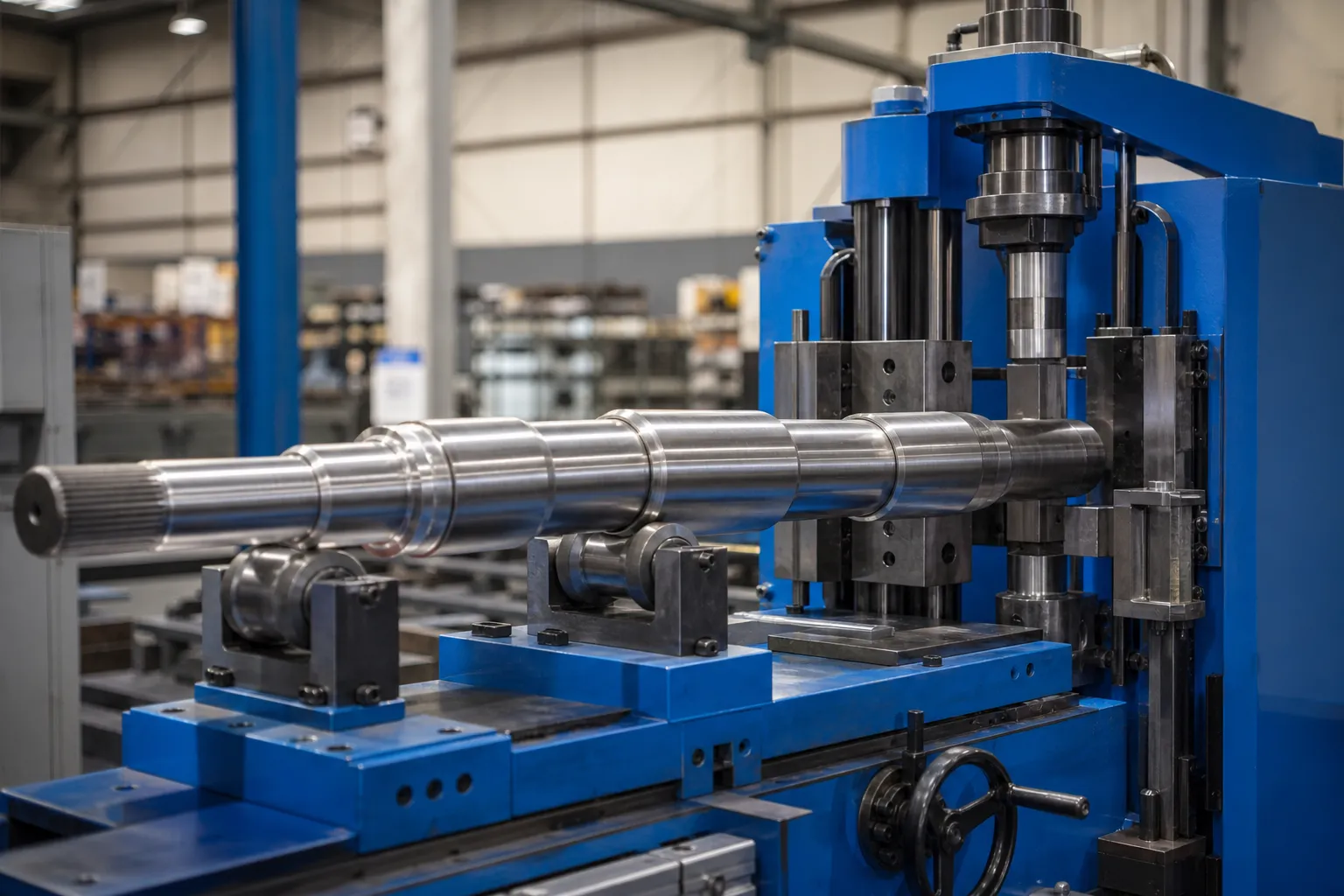
*Jeni konsèp ilistrasyon. It shows a candidate measurement-and-correction cell; actual sensors, sipò, force path and automation require workpiece-specific validation.*
Evaluate Contact and Section Integrity
The candidate machine must create an approved reaction path without damaging protected features. Review accessible support zones, permissible correction points, surface/coating requirements, length and mass handling, section transitions, epesè miray la, bore condition, seam orientation and downstream operations.
| Selection input | Poukisa li enpòtan |
|---|---|
| Contact and no-contact zones | Determines whether a support or correction route is even permissible |
| Section stiffness and wall condition | Changes response and local-damage risk |
| Incoming error distribution | Defines whether a local or continuous method can be evaluated |
| Etap fabrikasyon | Determines surface/allowance restrictions and the next process interface |
| Production mix | Affects changeover, recipe control and handling validation |
Compare Candidate Routes Conditionally
Point pressing can be evaluated where a discrete geometry map, support path and approved correction points exist. Roller or continuous straightening can be evaluated for compatible, sufficiently consistent sections. Detire, torsion or specialised routes may be candidates only when the workpiece, clamping, material and validation requirements support them. No method is a default guarantee.
Gade peze kont redresman roulo for the method boundary and pwen-press redresman for a closed-loop local-correction framework.
Define the Automation Boundary
“Automatic” should be decomposed into loading, idantifikasyon, oryantasyon, mezi, koreksyon, manyen, recipe management, traceability and exception routing. A system may automate some steps while retaining manual fixtures, engineering approval or customer-gauge verification. Do not use an automation label as a proxy for throughput, accuracy or labor savings.
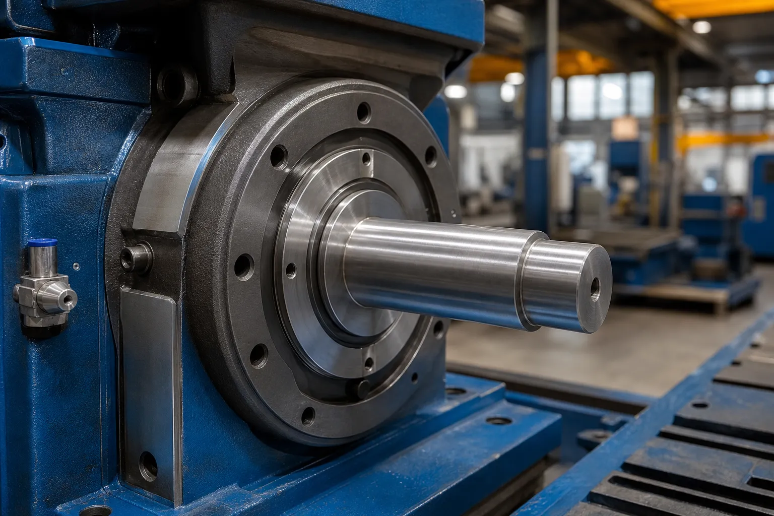
*Jeni konsèp ilistrasyon. It emphasizes released-part verification; it is not a customer acceptance report or a guaranteed performance result.*
Make the Sample Test the Selection Gate
The selection should close with representative normal and worst-case samples, a controlled drawing, agreed datum/gauge, raw before-and-after readings, remezurasyon eta lage, surface/section checks, maximum correction-attempt limits and a defined NOK route. Any promised accuracy, tan sik, handling rate or automation scope belongs only after that evidence is complete.
Sèvi ak redresman echantiyon tès ak akseptasyon to structure the trial, Prèv FAT ak SAT.
Information Needed for a Straightener Selection Review
Provide the workpiece drawing and variants, materyèl ak etap fabrikasyon, length/section/wall information, done jeyometri k ap vini yo, done fonksyonèl, zòn pwoteje, reference measurement method, sib pwodiksyon an, handling constraints and representative samples. StraighteningTech can then assess candidate measurement, support and correction architecture and identify the evidence needed before proposing a machine configuration.
FAQ
Can one machine process shafts, tubes and profiles?
Possibly for a defined and validated workpiece range, but not because all three are called “straightening.” The datum, section and contact route must be reviewed.
Is a faster machine automatically the better choice?
Non. Throughput has value only after geometry, sifas, measurement and exception handling meet the agreed acceptance method.
Can a product page replace a sample test?
Non. Product descriptions establish a category; a representative sample test establishes whether a specific workpiece family can be accepted.