
एक ड्राइव शाफ्ट एक साधारण लंबी ट्यूब की तरह दिख सकता है, लेकिन इसकी सीधी समस्या को संपूर्ण टॉर्क-ट्रांसमिशन ज्यामिति द्वारा परिभाषित किया गया है. ट्यूब बॉडी, वेल्डेड सिरे, योक, निकला हुआ किनारा, सार्वभौमिक-संयुक्त इंटरफेस और किसी भी केंद्र-असर वाली सुविधाओं को खोखले खंड को कुचलने या गतिशील असंतुलन के साथ ज्यामितीय रनआउट को भ्रमित किए बिना संरेखित रहना चाहिए.
इसलिए एक विश्वसनीय ड्राइव शाफ्ट स्ट्रेटनिंग समाधान पार्ट ड्राइंग से शुरू होता है, असेंबली चरण और स्वीकृति विधि. इसे कार्यात्मक संदर्भ अक्ष को परिभाषित करना होगा, कोणीय अभिविन्यास, मापने के स्टेशन, संरक्षित क्षेत्र, अनुमत सुधार क्षेत्र और स्ट्रेटनिंग और डाउनस्ट्रीम संतुलन प्रक्रिया के बीच संबंध.
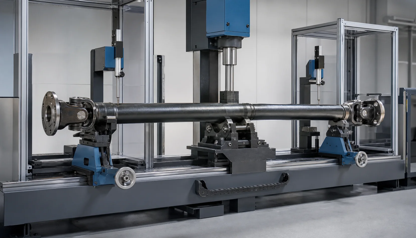
यह एक इंजीनियरिंग अवधारणा चित्रण है, ग्राहक-साइट की तस्वीर नहीं. वास्तविक मशीन अवधि, रक्षा, टूलींग, सेंसर और सुधार क्षमता ड्राइव शाफ्ट परिवार और नमूना परीक्षणों पर निर्भर करती है.
ड्राइव शाफ्ट को एक समर्पित स्ट्रेटनिंग समाधान की आवश्यकता क्यों है?
| ड्राइव दस्ता सुविधा | जोखिम को सीधा करना | परियोजना प्रतिक्रिया |
|---|---|---|
| खोखली वेल्डेड ट्यूब | स्थानीय लोडिंग से समस्या उत्पन्न हो सकती है, अंडाकारता या पतन | ट्यूब-विशिष्ट अनुरूप समर्थन और सुधार टूलींग का उपयोग करें |
| जुएं ख़त्म करो, फ्लैंज या कपलिंग | साधारण चक असंगत रूप से बैठ सकते हैं या इंटरफेस को नुकसान पहुंचा सकते हैं | दोहराए जाने योग्य कोणीय स्थिति के साथ अनुमोदित कार्यात्मक सुविधाओं का पता लगाएं |
| एक-टुकड़ा या बहु-टुकड़ा निर्माण | प्रत्येक अनुभाग में एक अलग संदर्भ और समर्थन स्थिति हो सकती है | सटीक असेंबली कॉन्फ़िगरेशन और माप मार्ग को फ़्रीज़ करें |
| वेल्डेड जोड़ | वेल्ड विरूपण ट्यूब अक्ष को स्थानांतरित कर सकता है और संबंध समाप्त कर सकता है | प्रासंगिक वेल्डिंग चरण से पहले और बाद में ड्राइंग-आधारित स्टेशनों पर माप लें |
| यूनिवर्सल-संयुक्त इंटरफ़ेस | संयुक्त क्लीयरेंस और अभिव्यक्ति सही संदर्भ को अस्पष्ट कर सकती है | परिभाषित करें कि जोड़ स्थापित हैं या नहीं, बंद, मास्टर्स द्वारा प्रतिस्थापित या बहिष्कृत |
| लंबी अवधि | स्व-भार और समर्थन स्थान मापा वक्र को बदल सकते हैं | ग्राहक गेज के साथ समर्थन निर्देशांक और सहसंबंध को मान्य करें |
| हाई-स्पीड ऑपरेशन | अपवाह और द्रव्यमान असंतुलन दोनों ही कंपन का कारण बन सकते हैं | ज्यामितीय सीधीकरण और गतिशील संतुलन को अलग-अलग नियंत्रण मानें |
| कोणीय चरण की आवश्यकता | सही रनआउट सही योक-टू-योक चरण की गारंटी नहीं देता है | एक स्वतंत्र विशेषता के रूप में चरण को मापें या यंत्रवत् संरक्षित करें |
इंजीनियरिंग का उद्देश्य केवल एक सुविधाजनक ट्यूब स्थान पर संकेतक आंदोलन को कम करना नहीं है. यह ट्यूब को संरक्षित करते हुए निर्दिष्ट ज्यामिति को नियंत्रित करने के लिए है, वेल्डेड जोन, संयुक्त इंटरफेस और डाउनस्ट्रीम संतुलन की स्थिति.
परिभाषित करें कि कौन सा "ड्राइव शाफ्ट" दायरे में है
ड्राइव शाफ़्ट, संचालक शक्ति का किरण, कार्डन शाफ्ट और ट्रांसमिशन शाफ्ट को कभी-कभी एक दूसरे के स्थान पर उपयोग किया जाता है. एक प्रस्ताव में सामान्य नाम को सटीक भाग परिवार से प्रतिस्थापित किया जाना चाहिए.
| भाग परिवार | विशिष्ट निर्माण | मुख्य सीधा प्रश्न |
|---|---|---|
| वन-पीस ऑटोमोटिव प्रोपेलर शाफ्ट | वेल्डेड योक या फ्लैंज के साथ खोखली ट्यूब | ट्यूब रनआउट, अंत संरेखण, चरण और संतुलन अनुक्रम |
| मल्टी-पीस प्रोपेलर शाफ्ट | केंद्र-असर सुविधाओं के साथ दो या दो से अधिक ट्यूबलर अनुभाग | अनुभाग संदर्भ, केंद्र-असर डेटाम और इकट्ठे व्यवहार |
| औद्योगिक कार्डन शाफ्ट | आर्टिकुलेटेड कपलिंग के साथ ट्यूबलर या ठोस शरीर | युग्मन स्थान, टेलीस्कोपिक अनुभाग और ऑपरेटिंग-कोण आवश्यकताएँ |
| नंगे ड्राइव-शाफ्ट ट्यूब | अंतिम अंत असेंबली से पहले ट्यूब | ट्यूब सीधापन, अंडाकारता और वेल्ड-तैयारी भत्ता |
| इकट्ठे ड्राइव शाफ्ट | नली, योक, जोड़, फ्लैंज और संतुलन भार | पूर्ण-असेंबली रनआउट, चरण और अंतिम संतुलन सत्यापन |
प्रस्तुत ड्राइंग और नमूने में यह अवश्य दर्शाया जाना चाहिए कि लक्ष्य एक नंगी ट्यूब है या नहीं, एक वेल्डेड शाफ्ट, एक संयुक्त असेंबली या एक तैयार संतुलित घटक. एक चरण में मान्य प्रक्रिया को स्वचालित रूप से दूसरे चरण में स्थानांतरित नहीं किया जा सकता है.
ड्राइव शाफ्ट रखें, एक्सल शाफ्ट और स्टीयरिंग शाफ्ट की सामग्री अलग-अलग
ये सभी घटक गति या टॉर्क संचारित करते हैं, लेकिन उनकी ज्यामिति और स्वीकृति तर्क विनिमेय नहीं हैं.
| अवयव | सामान्य ज्यामिति | समर्पित सामग्री फोकस |
|---|---|---|
| गाड़ी चलाना / संचालक शक्ति का किरण | वेल्डेड योक के साथ लंबी खोखली ट्यूब, फ्लैंज या कपलिंग | ट्यूब सुरक्षा, अंत संरेखण, चरण, रनआउट और संतुलन सीमा |
| धुरा / आधा शाफ़्ट | आमतौर पर ठोस या स्थानीय रूप से खोखला स्टेप्ड शाफ्ट स्प्लाइन और संभावित व्हील फ्लैंज के साथ | पत्रिका, पट्टी, शाफ़्ट-बॉडी और फ़्लैंज संबंध |
| स्टीयरिंग शॉफ़्ट | छोटा स्टीयरिंग-कॉलम ट्रांसमिशन सदस्य, अक्सर दूरबीन या संयुक्त | स्टीयरिंग इंटरफ़ेस ज्यामिति, कोलैप्सिबल/टेलीस्कोपिक विशेषताएं और सुरक्षा-विशिष्ट आवश्यकताएं |
पुराने ऑटोमोटिव पार्ट्स और स्टीयरिंग शाफ्ट पृष्ठ नेविगेशन परतें बने रह सकते हैं. यह पृष्ठ प्रत्येक ऑटोमोटिव शाफ्ट को एक ही वर्कपीस के रूप में माने बिना ड्राइव-शाफ्ट-विशिष्ट विनिर्माण और उपकरण प्रश्नों का उत्तर देता है.
विनिर्माण और मरम्मत चरण को रोकें
पसंदीदा सीधा करने का मार्ग शाफ्ट की स्थिति के साथ बदलता है.
अंतिम वेल्डिंग से पहले नंगी ट्यूब
एक नंगी ट्यूब सरल पहुंच प्रदान करती है, लेकिन बाद में वेल्डिंग नई विकृति ला सकती है. इस स्तर पर सीधा करना आने वाली ट्यूब नियंत्रण या तैयारी के लिए उपयोगी हो सकता है, फिर भी यह वेल्ड के बाद के माप को प्रतिस्थापित नहीं करता है.
अंतिम मशीनिंग से पहले वेल्डेड दस्ता
जुएं ख़त्म करो, फ्लैंज या स्टब्स पहले से ही जुड़े हुए हैं, ताकि सिस्टम ट्यूब से उनके संबंध का मूल्यांकन कर सके. शेष मशीनिंग भत्ता और ताप इनपुट को योजना में शामिल किया जाना चाहिए.
संतुलन बनाने से पहले समाप्त दस्ता
यह चरण संतुलन मशीन में प्रवेश करने वाली ज्यामितीय स्थिति स्थापित कर सकता है. सतह की सुरक्षा, संयुक्त संचालन और सुधार सीमाएँ अधिक प्रतिबंधात्मक हो जाती हैं क्योंकि भाग में पहले से ही अधिक मूल्य जोड़ा जा चुका है.
पहले से संतुलित दस्ता
यदि शेष भार मौजूद हैं, दबाने से ट्यूब की ज्यामिति बदल सकती है, वजन की स्थिति या मापी गई संतुलन की स्थिति. जब तक ग्राहक प्रक्रिया स्पष्ट रूप से अन्यथा प्रदर्शित न हो, भाग को सीधा करने के बाद अनुमोदित संतुलन जांच में वापस आना चाहिए.
शाफ्ट का पुनर्निर्माण या मरम्मत करें
घिसाव, डेंटिंग, क्षतिग्रस्त जोड़, गलत वेल्ड और पिछले सुधार प्रयास स्ट्रेटनिंग को अनुपयुक्त बना सकते हैं. निरीक्षण योजना में अस्वीकृति नियम शामिल होने चाहिए; एक स्वचालित स्ट्रेटनर संरचनात्मक मरम्मत मूल्यांकन का विकल्प नहीं है.
नियंत्रित विशेषता को परिभाषित करें
पूर्ण स्वीकृति आवश्यकता के रूप में "सीधे शाफ्ट" का उपयोग न करें. ड्राइंग को अलग से नियंत्रित किया जा सकता है:
- ट्यूब या शाफ़्ट-अक्ष सीधापन;
- निर्दिष्ट ट्यूब स्टेशनों पर सर्कुलर रनआउट या कुल रनआउट;
- अंत पायलटों का रनआउट, पत्रिकाओं, निकला हुआ किनारा चेहरे या युग्मन सुविधाएँ;
- अंतिम विशेषताओं की संकेंद्रितता या समाक्षीय संबंध;
- योक या निकला हुआ कोणीय चरण;
- ट्यूब का बाहरी व्यास और अंडाकारता;
- वेल्ड-संबंधित ज्यामिति और अनुमत सुधार क्षेत्र;
- संपूर्ण घूर्णनशील असेंबली का अवशिष्ट असंतुलन;
- अंतिम सिस्टम परीक्षण में कार्यात्मक कंपन या शोर.
स्ट्रेटनिंग ज्यामितीय रनआउट को प्रभावित कर सकता है, लेकिन यह चरण त्रुटि को स्वचालित रूप से ठीक नहीं करता है, संयुक्त पहनना, निकला हुआ किनारा-चेहरा त्रुटि, वेल्ड गुणवत्ता या द्रव्यमान असंतुलन. समीक्षा दस्ता सीधापन बनाम रनआउट बनाम टीआईआर ड्राइंग आवश्यकता को संकेतक सेटअप में परिवर्तित करने से पहले.
कार्यात्मक संदर्भ से माप बनाएं
संदर्भ अक्ष को ड्राइंग से मेल खाना चाहिए या ग्राहक गेज के साथ दस्तावेज़ीकृत सहसंबंध होना चाहिए. संभावित संदर्भ प्राप्ति में शामिल हैं:
पायलट या फ्लैंज रजिस्टर समाप्त करें
सटीक पायलट या रजिस्टर स्थापित घूर्णी अक्ष को पुन: उत्पन्न कर सकते हैं जब उनका रूप और स्थिति उपयुक्त हो. स्थान निर्धारित करने वाले चेहरे साफ़ होने चाहिए, क्षतिरहित और लगातार बैठा हुआ.
यूनिवर्सल-संयुक्त या योक इंटरफेस
समर्पित स्वामी या चक संयुक्त इंटरफ़ेस से पता लगा सकते हैं. मंजूरी, बेयरिंग-कप की स्थिति और संयुक्त जोड़ को नियंत्रित किया जाना चाहिए ताकि फिक्स्चर गलत रनआउट न पैदा करे.
बियरिंग या सेंटर-बियरिंग जर्नल
मल्टी-पीस शाफ्ट पर, केंद्र-असर वाली पत्रिका कार्यात्मक सहायता प्रणाली का हिस्सा हो सकती है. माप योजना में अवश्य बताया जाना चाहिए कि क्या यह एक डेटाम है, एक निरीक्षण सुविधा या केवल एक अस्थायी मशीन समर्थन.
एकाधिक विशेषताओं से गणितीय अक्ष
सेंसर चयनित पायलटों को माप सकते हैं, जर्नल या ट्यूब स्टेशन और संबंधित संदर्भ अक्ष की गणना करें. एल्गोरिथ्म, स्टेशन निर्देशांक, फ़िल्टरिंग और बाहरी नियमों को अनुमोदित गेज के विरुद्ध मान्य किया जाना चाहिए.
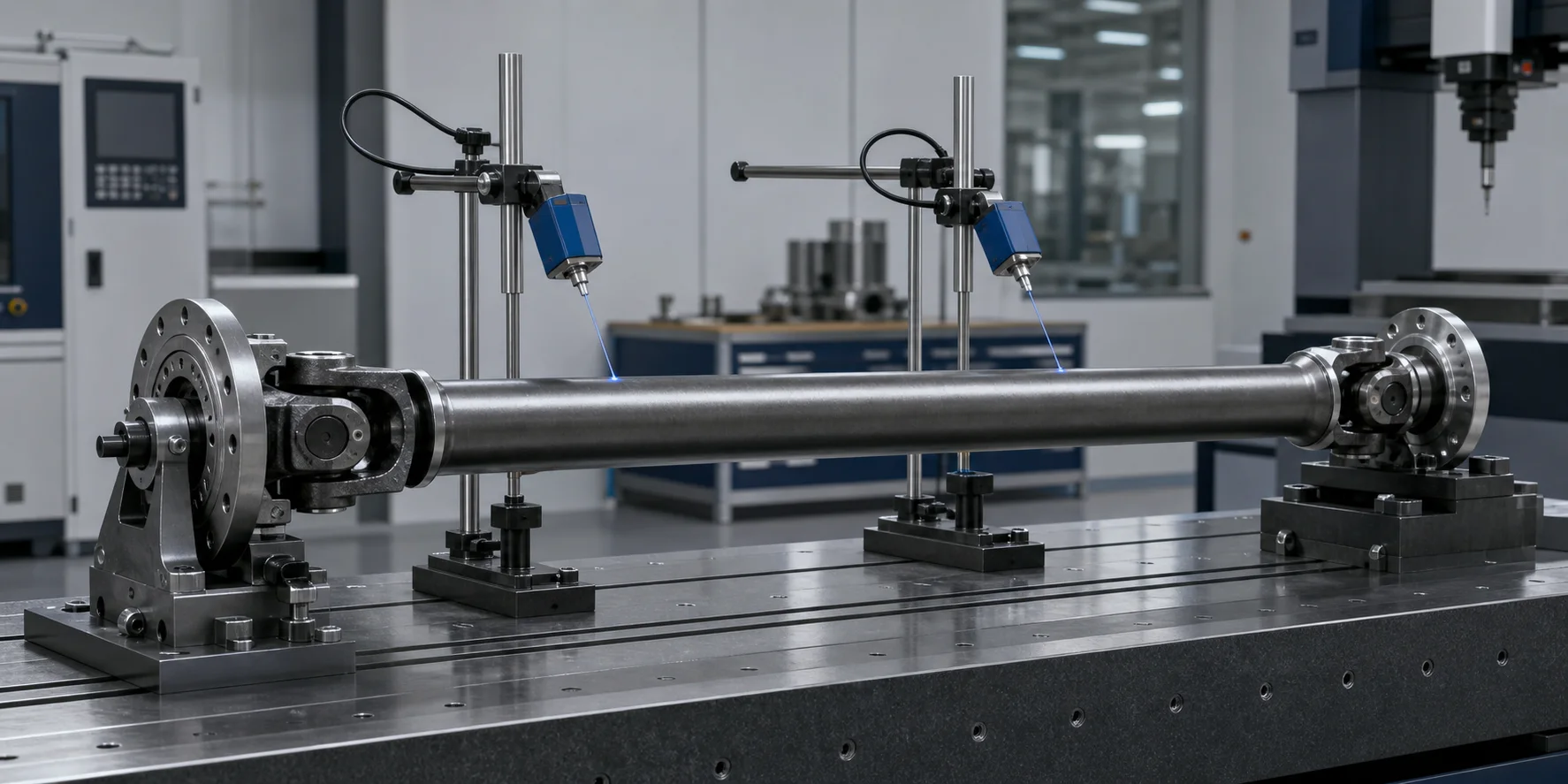
यह इंजीनियरिंग अवधारणा चित्रण गैर-संपर्क ट्यूब माप और अंत-सुविधा अभिविन्यास दिखाता है. यह प्रत्येक प्रोजेक्ट के लिए एक विशिष्ट सेंसर तकनीक निर्धारित नहीं करता है.
किसी अनियमित ट्यूब सतह को वास्तविक अक्ष के रूप में न पढ़ें
एक वेल्डेड या गठित ट्यूब में स्थानीय सतह भिन्नता हो सकती है, सीवन प्रभाव, कलई करना, वेल्ड छींटे या अंडाकारता. इसलिए एक परिधीय ट्रैक पर पढ़ने वाले सेंसर में केंद्र रेखा गति और सतह-रूप त्रुटि दोनों शामिल हो सकते हैं.
| माप चर | संभावित ग़लत संकेत | नियंत्रण विधि |
|---|---|---|
| ट्यूब की सतह की बनावट | अल्पावधि विस्थापन भिन्नता | एक स्वीकृत ट्रैक का चयन करें और फ़िल्टरिंग को मान्य करें |
| ओवेलिटि | दो-लोब सिग्नल जो रनआउट जैसा दिखता है | व्यास/रूप को अलग से मापें या एकाधिक संवेदन दिशाओं का उपयोग करें |
| वेल्ड सीम | स्थानीय शिखर या परावर्तनशीलता में परिवर्तन | सीम हैंडलिंग और सेंसर उपयुक्तता को परिभाषित करें |
| कोटिंग या संदूषण | अस्थिर संपर्क या ऑप्टिकल प्रतिक्रिया | स्वच्छता और सतह-स्थिति नियम निर्धारित करें |
| संयुक्त निकासी | अंतिम फीचर ट्यूब मोड़ के बिना चलता है | ताला, प्रीलोड, मान्य के रूप में जोड़ को मास्टर करें या बाहर करें |
| स्थिरता बैठने की व्यवस्था | पुनः-क्लैम्पिंग से संकेतित उच्च बिंदु बदल जाता है | रिपीट-लोड और रि-सीट अध्ययन संचालित करें |
| लंबे समय तक शिथिलता | समर्थन-निर्भर स्पष्ट वक्रता | समर्थन स्थिति और अभिविन्यास को फ़्रीज़ करें |
माप प्रणाली को कई अक्षीय स्टेशनों को मैप करना चाहिए, एक मध्यबिंदु रीडिंग से पूरे शाफ्ट का अनुमान न लगाएं. जब ट्रैसेबिलिटी की आवश्यकता होती है तो इसे प्रक्रिया समीक्षा के लिए कच्चे या सारांशित स्टेशन डेटा को भी संरक्षित करना चाहिए.
योक और फ्लैंज चरण को सुरक्षित रखें
चरणबद्धता अंतिम विशेषताओं के बीच कोणीय संबंध का वर्णन करती है, विशेष रूप से योक. यह सीधेपन के समान नहीं है और इसे केवल इसलिए ठीक नहीं किया जाता है क्योंकि ट्यूब रनआउट कम हो जाता है.
परियोजना को परिभाषित करना चाहिए:
- वह सुविधा जो शून्य कोण स्थापित करती है;
- अनुमत चरण संबंध और सहनशीलता;
- संयुक्त खेल के बिना प्रत्येक छोर कैसे स्थित है;
- क्या मशीन केवल चरण को सुरक्षित रखती है या उसका सत्यापन भी करती है;
- क्या प्रत्येक कोणीय अभिविन्यास पर दबाने की अनुमति है;
- एक असफल चरण जांच को कैसे संभाला जाता है;
- क्या सीधा करने से पहले चरण की जाँच की जाती है, सीधा करने के बाद या दोनों चरणों में.
एक कोणीय लोकेटर, दृष्टि प्रणाली या सुविधा-विशिष्ट जांच उपयुक्त हो सकती है, लेकिन चयन सटीक योक पर निर्भर करता है, निकला हुआ, रिंग या युग्मन ज्यामिति. मशीन को शाफ्ट को कभी भी ऐसे सुधारात्मक अभिविन्यास में नहीं घुमाना चाहिए जो एक नाजुक विशेषता रखता हो, weld or balance weight in an unsafe load path.
Protect the Hollow Tube from Collapse and Indentation
Tube protection is the defining tooling problem for many propeller shafts. Narrow supports or a small press nose can create a locally acceptable runout result while permanently damaging the cross-section.
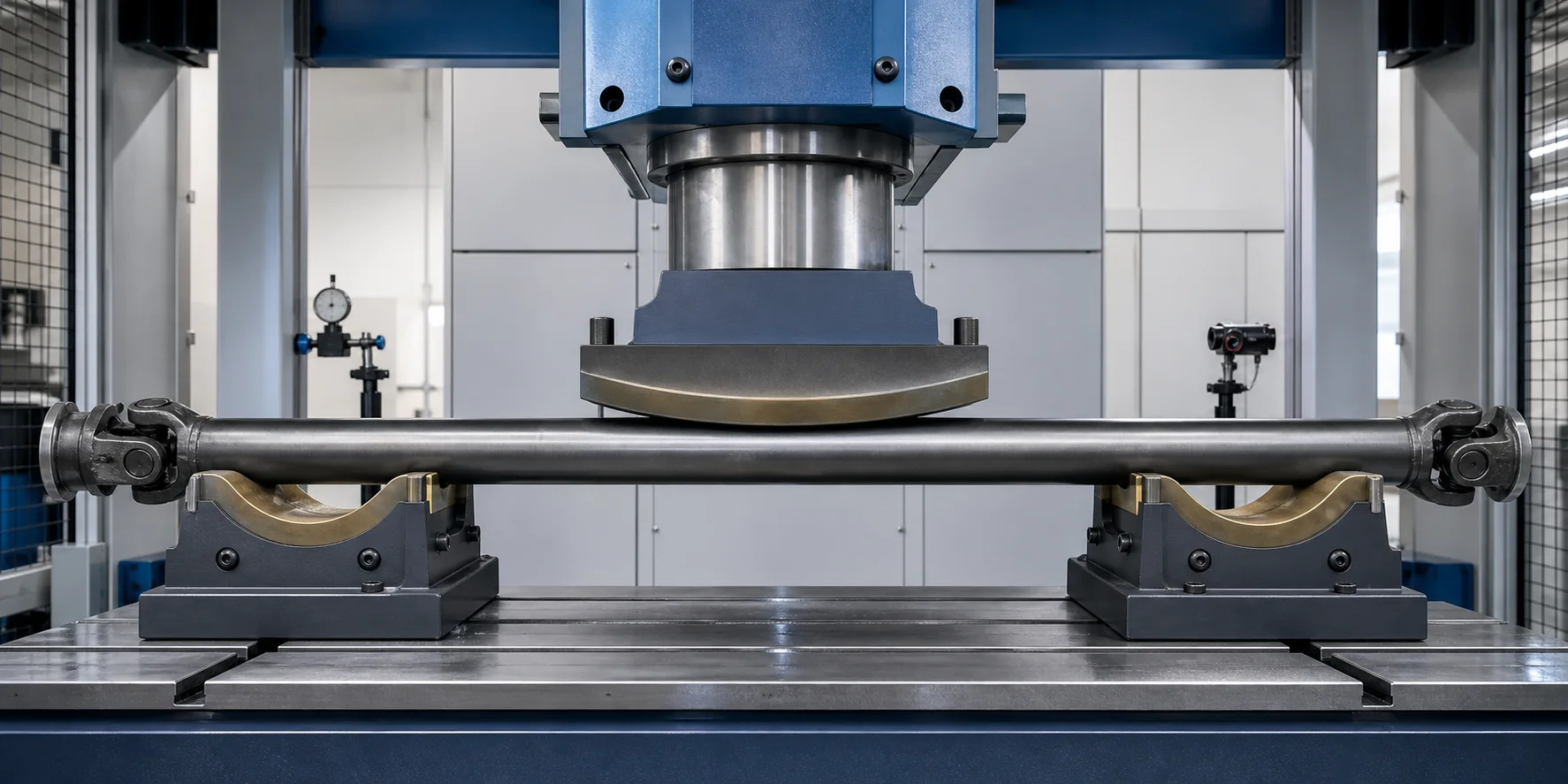
This engineering concept illustration shows broad conforming contact. Actual saddle radius, liner, contact length and force limit require representative sample validation.
Conforming Supports
Broad saddles can distribute reaction force over a larger arc. Their diameter match, liner material, edge radius and cleanliness must be selected for the tube surface and load.
Enveloping Correction Tooling
एक त्रिज्यायुक्त या घेरने वाला प्रेस जूता एक संकीर्ण पंच की तुलना में स्थानीय संपर्क तनाव को कम कर सकता है. इसे अभी भी चयनित अवधि में पर्याप्त नियंत्रित झुकने वाला क्षण प्रदान करना होगा.
आवश्यकता पड़ने पर आंतरिक सहायता
कुछ ट्यूब परिवारों को एक खराद का धुरा की आवश्यकता हो सकती है, प्लग या अन्य आंतरिक समर्थन. आंतरिक टूलींग पहुंच जोड़ता है, परिवर्तन और जोखिमों को चिह्नित करना, इसलिए इसका उपयोग तभी किया जाना चाहिए जब नमूना अध्ययन से इसकी आवश्यकता का पता चले.
अंडाकारता और सतह की जाँच
सुधार के बाद की स्वीकृति में निर्दिष्ट ट्यूब व्यास शामिल होना चाहिए, ओवेलिटि, सेंध और सतह मानदंड. एक शाफ्ट केवल इसलिए स्वीकार्य नहीं है क्योंकि उसके रेडियल संकेतक मूल्य में सुधार हुआ है.
मानचित्र वेल्ड, संतुलन भार और नो-प्रेस जोन
ड्राइंग और नमूना समीक्षा में उन सभी क्षेत्रों की पहचान होनी चाहिए जिन्हें लोड या संपर्क नहीं किया जा सकता है:
- परिधीय या अनुदैर्ध्य वेल्ड;
- परियोजना-विशिष्ट प्रतिबंधों के साथ गर्मी प्रभावित क्षेत्र;
- वजन और उनके लगाव क्षेत्र को संतुलित करें;
- योक या फ्लैंज के पास पतले संक्रमण;
- ग्रीस फिटिंग, सील और संयुक्त हार्डवेयर;
- विभाजन, धागे, पायलट और तैयार असर वाली सतहें;
- लेबल, कोटिंग्स या संक्षारण-संरक्षण क्षेत्र;
- छात्रों, दरारें या पूर्व मरम्मत क्षेत्र जिन्हें अस्वीकृति की आवश्यकता होती है.
नुस्खा को इन विशेषताओं को अक्षीय और कोणीय रखरखाव क्षेत्रों में परिवर्तित करना चाहिए. जब सुरक्षित सुधार विंडो बहुत छोटी हो, सही निर्णय असुरक्षित सुधार को मजबूर करने के बजाय विनिर्माण अनुक्रम को बदलना या भाग को अस्वीकार करना हो सकता है.
अनुशंसित बंद-लूप सीधीकरण प्रक्रिया
1. भाग और प्रक्रिया चरण को पहचानें
भाग संख्या से मान्य नुस्खा चुनें, बारकोड या डेटा मैट्रिक्स. पुष्टि करें कि क्या भाग एक नंगी ट्यूब है, वेल्डेड शाफ्ट, इकट्ठे शाफ्ट या मरम्मत किए गए घटक.
2. निरीक्षण करें और सुरक्षित रूप से लोड करें
दृश्यमान डेंट की जाँच करें, क्षतिग्रस्त जोड़, वजन कम करना, गंभीर वेल्ड दोष या अन्य अस्वीकार स्थितियाँ. योक पर प्रहार किए बिना शाफ्ट को लोड करें, फ्लैंगेस या ट्यूब सतह.
3. कार्यात्मक डेटाम और कोणीय विशेषता का पता लगाएं
अनुमोदित अंत इंटरफेस को स्थापित करें और चरण संदर्भ स्थापित करें. रोटेशन या माप से पहले अपूर्ण बैठने का पता लगाएं.
4. एकाधिक अक्षीय स्टेशनों को मापें
नियंत्रित परिस्थितियों में घूमें और निर्दिष्ट स्टेशनों से मोड़/रनआउट मानचित्र बनाएं. मान्य विधि का उपयोग करके ज्ञात सतह-रूप प्रभावों को केंद्र रेखा गति से अलग करें.
5. एक सुरक्षित सुधार क्षेत्र चुनें
नियंत्रण तर्क विचलन मानचित्र को ट्यूब कठोरता के साथ जोड़ता है, समर्थन अवधि, वेल्ड स्थान, अंत ज्यामिति, चरण अभिविन्यास और सभी नो-प्रेस जोन.
6. नियंत्रित ओवर-बेंडिंग लागू करें
स्वीकृत निर्देशांकों के लिए व्यापक समर्थन और अनुरूप सुधार टूलींग ले जाएँ. मान्य मॉडल के अनुसार सीमित सुधार स्ट्रोक या बल लागू करें.
7. रिहाई और उपाय
परिणाम आंकने से पहले सुधार भार हटा दें. संबंधित स्टेशनों को फिर से मापें और स्प्रिंगबैक मॉडल को अपडेट करें. शाफ्ट स्ट्रेटनिंग में स्प्रिंगबैक मुआवजा बताता है कि लोडेड विस्थापन अंतिम ज्यामिति क्यों नहीं है.
8. स्वतंत्र विशेषताओं का सत्यापन करें
आवश्यक रनआउट स्टेशनों की पुष्टि करें, चरण, अंत-सुविधा ज्यामिति, ट्यूब अंडाकारता, सतह की स्थिति और किसी निर्दिष्ट वेल्ड-ज़ोन की जाँच. नियंत्रण योजना द्वारा परिभाषित अनुसार शाफ्ट को संतुलन या अंतिम असेंबली में रूट करें.
9. रिकॉर्ड करें और अनलोड करें
भाग की पहचान संग्रहित करें, नुस्खा संशोधन, पहले/बाद के मान, सुधार इतिहास, जब ट्रैसेबिलिटी की आवश्यकता होती है तो अलार्म और स्वभाव. जोड़ की स्थिति बदले बिना या तैयार सतहों को नुकसान पहुंचाए बिना अनलोड करें.
स्ट्रेटनिंग और डायनेमिक बैलेंसिंग अलग-अलग प्रक्रियाएं हैं
ज्यामितीय रनआउट वर्णन करता है कि रोटेशन के दौरान किसी संदर्भ के सापेक्ष वास्तविक सतह या सुविधा कैसे चलती है. गतिशील असंतुलन बड़े पैमाने पर वितरण और असेंबली के घूमने पर उत्पन्न बलों/क्षणों का वर्णन करता है. एक ड्राइव शाफ्ट ज्यामितीय रूप से सीधा लेकिन असंतुलित हो सकता है, या अस्वीकार्य रनआउट प्रदर्शित करते हुए भी कम अवशिष्ट असंतुलन है.
| प्रक्रिया | प्राथमिक इनपुट | विशिष्ट सुधार | यह क्या साबित नहीं करता |
|---|---|---|---|
| सीधा | मोड़/रनआउट मानचित्र और अनुमोदित ज्यामितीय डेटाटम्स | सुरक्षित स्थानों पर नियंत्रित झुकना | अवशिष्ट असंतुलन सहनशीलता के भीतर है |
| चरण सत्यापन | निर्दिष्ट अंतिम विशेषताओं का कोणीय संबंध | असेंबली/अनुक्रमण सुधार या अस्वीकृति | ट्यूब सेंटरलाइन और बड़े पैमाने पर वितरण स्वीकार्य हैं |
| गतिशील संतुलन | एक या अधिक तलों में परिमाण और कोण का असंतुलित घूमना | जोड़ना, किसी अनुमोदित विधि का उपयोग करके द्रव्यमान को हटाएँ या स्थानांतरित करें | दस्ता ज्यामिति, वेल्ड अखंडता या चरण स्वीकार्य है |
कई पूर्ण शाफ्टों के लिए, रक्षात्मक मार्ग अंतिम संतुलन से पहले अत्यधिक रनआउट को ठीक करना है और फिर किसी भी बाद के ज्यामितीय सुधार के बाद संतुलन को सत्यापित करना है. सटीक क्रम ग्राहक के ड्राइंग के अनुरूप होना चाहिए, संतुलन विशिष्टता और मान्य विनिर्माण मार्ग. स्ट्रेटनिंग बैलेंसिंग मशीन का विकल्प नहीं है.
प्वाइंट प्रेस स्ट्रेटनिंग या रोलर स्ट्रेटनिंग?
एक पूर्ण प्रोपेलर शाफ्ट में आम तौर पर अलग-अलग योक होते हैं, निकला हुआ किनारा, वेल्ड और संरक्षित क्षेत्र. ये सुविधाएँ अक्सर समर्पित समर्थन के साथ नियंत्रित बिंदु-प्रेस सुधार का समर्थन करती हैं क्योंकि मशीन चयनित अक्षीय और कोणीय स्थानों को लक्षित कर सकती है.
रोलर स्ट्रेटनिंग उपयुक्त नंगे स्थिर-खंड ट्यूब या बार स्टॉक के लिए प्रासंगिक हो सकती है, लेकिन इसे तैयार संयुक्त शाफ्ट के लिए उपयुक्त नहीं माना जाना चाहिए. समीक्षा प्रेस स्ट्रेटनिंग बनाम रोलर स्ट्रेटनिंग प्रक्रिया परिवार का चयन करने से पहले.
प्रस्तावित ड्राइव शाफ्ट स्ट्रेटनिंग सेल
| कोशिका कार्य | परियोजना-विशिष्ट विन्यास |
|---|---|
| भाग संचालन | नियमावली, द्रव्यमान के आधार पर सहायता प्राप्त या स्वचालित लोडिंग, लंबाई और आयतन |
| अंतिम स्थान | समर्पित निकला हुआ किनारा, पायलट, सीटिंग डिटेक्शन के साथ योक या कपलिंग टूलींग |
| कोणीय स्थिति | यांत्रिक लोकेटर, एनकोडर, मान्य के रूप में दृष्टि या सुविधा सेंसर |
| ROTATION | संयुक्त/स्थिरता सुरक्षा जांच के साथ नियंत्रित कम गति अनुक्रमण |
| माप | ड्राइंग-आधारित स्टेशनों पर संपर्क या गैर-संपर्क सेंसर |
| सहायता | समायोज्य चौड़ी काठी ट्यूब व्यास और सुधार भार से मेल खाती है |
| सुधार | बल/विस्थापन निगरानी के साथ सर्वो-इलेक्ट्रिक या हाइड्रोलिक प्रेस इकाई |
| पकाने की विधि नियंत्रण | आंशिक-पारिवारिक पैरामीटर, संरक्षित क्षेत्र और पुनरीक्षण प्रबंधन |
| गुणवत्ता की जाँच | रन आउट, चरण, ट्यूब फार्म, सतह और आवश्यक अंतिम-सुविधा जांच |
| पता लगाने की क्षमता | पहले/बाद का डेटा, सुधार इतिहास, अलार्म और स्वभाव |
| सुरक्षा | रखवाली, भाग रोटेशन और संग्रहीत ऊर्जा के लिए इंटरलॉक और जोखिम मूल्यांकन |
मशीन की क्षमता का चयन केवल समग्र शाफ्ट लंबाई से नहीं किया जा सकता है. ट्यूब का व्यास और दीवार की मोटाई, सामग्री, उपज व्यवहार, समर्थन अवधि, अंत द्रव्यमान, आने वाली विकृति और सुरक्षित संपर्क क्षेत्र सभी आवश्यक बल को प्रभावित करते हैं, स्ट्रोक और टूलींग.
नमूना परीक्षण और स्वीकृति
अंतिम मशीन और टूलींग प्रतिबद्धताओं से पहले एक प्रतिनिधि नमूना अध्ययन आवश्यक है. नमूना सेट को कवर करना चाहिए:
- न्यूनतम और अधिकतम ट्यूब व्यास, दीवार की मोटाई और लंबाई;
- एक-टुकड़ा और बहु-टुकड़ा वेरिएंट, यदि दोनों दायरे में हैं;
- सभी प्रासंगिक योक, निकला हुआ किनारा और युग्मन इंटरफ़ेस;
- वास्तविक सामग्री, उष्मा उपचार, वेल्ड की स्थिति और कोटिंग;
- यथार्थवादी आने वाली रनआउट परिमाण और मोड़ स्थान;
- लागू होने पर अनुमोदित शेष भार वाले हिस्से;
- सामान्य और कठिन चरण अभिविन्यास;
- ग्राहक-अनुमोदित माप और संतुलन सहसंबंध नमूने.
स्वीकृति योजना को आने वाले वितरण को परिभाषित करना चाहिए, लक्ष्य विशेषताएँ, गेज समझौता, रिपीट-लोड रिपीटेबिलिटी, सतह और अंडाकार सीमा, अनुमत सुधार गिनती, दरार या वेल्ड निरीक्षण आवश्यकताएँ, चक्र-समय सीमा, पता लगाने की क्षमता और गैर-अनुरूप भागों का स्वभाव.
उपयोग नमूना परीक्षण और स्वीकृति मार्गदर्शिका को सीधा करना गारंटीकृत परिणाम का अनुरोध करने से पहले एक साझा प्रोटोकॉल बनाना.
ड्राइव शाफ्ट प्रस्ताव के लिए आवश्यक जानकारी
स्वचालित ड्राइव शाफ्ट स्ट्रेटनिंग समाधान का मूल्यांकन करने के लिए, उपलब्ध करवाना:
- 2डी ड्राइंग और, कब उपलब्ध है, 3डी मॉडल;
- भाग के नाम और एक-टुकड़ा/बहु-टुकड़ा निर्माण;
- कुल लंबाई, ट्यूब का बाहरी व्यास और दीवार की मोटाई;
- सामग्री, उष्मा उपचार, कोटिंग और वेल्ड की जानकारी;
- घोड़े का अंसबंध, निकला हुआ, युग्मन और केंद्र-असर विवरण;
- असेंबली चरण जिस पर स्ट्रेटनिंग होगी;
- आरेखण डेटाम और प्रत्येक नियंत्रित रनआउट/सीधेपन स्टेशन;
- चरण आवश्यकता और संदर्भ सुविधाएँ;
- आने वाली विकृति वितरण, न केवल सबसे खराब नमूना;
- अनुमत समर्थन और सुधार क्षेत्र;
- संरक्षित सतहें, वेल्ड, वजन और नो-प्रेस जोन;
- ओवेलिटि, काटने का निशान, सतह और दरार स्वीकृति नियम;
- संतुलन चरण, specification and required process sequence;
- मॉडल मिश्रण, बैच का आकार, target throughput and loading method;
- पता लगाने की क्षमता, data export and line-integration requirements;
- प्रतिनिधि अच्छा, विशिष्ट और कठिन नमूने;
- customer gauge or gauge-correlation method.
We use this information to configure the measuring reference, end tooling, angular positioning, समर्थन अवधि, tube-protection tooling, correction model and validation plan. Where the evidence is incomplete, the proposal should remain conditional until sample testing closes the gap.
अक्सर पूछे जाने वाले प्रश्न
Can a drive shaft straightener also balance the shaft?
स्वचालित रूप से नहीं. Straightening controls specified geometry; balancing measures and corrects mass distribution during rotation. A production cell may connect both operations, but each needs its own measurement system, correction method and acceptance criteria.
Why should runout be corrected before final balancing?
अत्यधिक ज्यामितीय रनआउट दोहराए जाने योग्य समर्थन और घूर्णन व्यवहार में हस्तक्षेप कर सकता है. इसे पहले ठीक करने से संतुलन के लिए अधिक स्थिर इनपुट मिल सकता है. तथापि, अनुमोदित आदेश को सटीक शाफ्ट के लिए मान्य किया जाना चाहिए, टूलींग और संतुलन विशिष्टता.
क्या मशीन सार्वभौमिक जोड़ों वाले शाफ्ट को सीधा कर सकती है??
यह समर्पित टूलींग और नियंत्रित संयुक्त स्थिति के साथ संभव हो सकता है. संयुक्त क्लीयरेंस और आर्टिक्यूलेशन गलत माप बना सकते हैं, इसलिए परियोजना को यह परिभाषित करना होगा कि जोड़ कैसे स्थित हैं, मास्टर्स द्वारा लॉक या प्रतिनिधित्व किया गया.
आप एक खोखली ट्यूब को कुचलने से कैसे बचाते हैं??
समाधान ट्यूब-विशिष्ट समर्थन और व्यापक अनुरूप सैडल जैसी सुधार अवधारणाओं का उपयोग करता है, त्रिज्यायुक्त या घेरने वाले प्रेस वाले जूते, बल/स्ट्रोक सीमाएँ और, जब उचित हो, आंतरिक समर्थन. वास्तविक डिज़ाइन को प्रतिनिधि नमूनों पर सिद्ध किया जाना चाहिए और अंडाकारता और सतह क्षति के लिए जाँच की जानी चाहिए.
क्या स्वीकार्य ट्यूब रनआउट सही योक चरण साबित होता है?
नहीं. रनआउट और चरण स्वतंत्र विशेषताएँ हैं. चरण संदर्भ और सहनशीलता को अलग से मापा या यंत्रवत् संरक्षित किया जाना चाहिए.
क्या एक मशीन विभिन्न ड्राइव शाफ्ट लंबाई और व्यास को संभाल सकती है??
हाँ, जब वर्कपीस परिवार मान्य बल के अंतर्गत आते हैं, अवधि, ROTATION, सेंसर और टूलींग लिफाफा. समायोज्य स्टेशन और संग्रहीत व्यंजन मॉडल परिवर्तन का समर्थन कर सकते हैं, लेकिन अंतिम इंटरफेस और ट्यूब व्यास के लिए समर्पित टूलींग की आवश्यकता हो सकती है.
क्या पहले से संतुलित ड्राइव शाफ्ट को सीधा किया जा सकता है??
संभावित, लेकिन सुधार संतुलन की स्थिति या संतुलन भार को प्रभावित कर सकता है. जब तक ग्राहक प्रक्रिया स्पष्ट रूप से कोई अन्य मार्ग स्थापित नहीं कर लेती, तब तक भाग को सीधा करने के बाद अनुमोदित संतुलन सत्यापन में वापस कर दिया जाना चाहिए.
उपयोगी प्रस्ताव प्राप्त करने का सबसे तेज़ तरीका क्या है??
Evaluating drive shaft straightening for a production line? से शुरू करें machine selection guide for shafts, ट्यूब और प्रोफाइल और यह price breakdown for straightening machines इससे पहले कि आप कोटेशन का अनुरोध करें.
ड्राइंग भेजें, ट्यूब आयाम, सभा मंच, रनआउट और चरण आवश्यकताएँ, संतुलन क्रम, संरक्षित क्षेत्र, आने वाले भाग डेटा और प्रतिनिधि नमूने. मशीन सटीकता संख्या के लिए सामान्य अनुरोध की तुलना में एक स्पष्ट माप संदर्भ अधिक मूल्यवान है.
संपूर्ण घूर्णनशील असेंबली से समाधान बनाएं
एक ड्राइव शाफ्ट स्ट्रेटनिंग समाधान को ट्यूब सेंटरलाइन से अधिक सुरक्षा प्रदान करनी चाहिए. इसे कार्यात्मक अक्ष का समन्वय करना होगा, ट्यूब फार्म, वेल्डेड सिरे, योक या निकला हुआ किनारा चरण, संरक्षित सुविधाएँ और डाउनस्ट्रीम संतुलन मार्ग.
स्ट्रेटनिंग समाधान प्रदाता और उपकरण निर्माता के रूप में, हम मशीन को वर्कपीस और स्वीकृति विधि के आसपास कॉन्फ़िगर करते हैं. अपनी ड्राइव शाफ्ट ड्राइंग साझा करें, नमूना स्थिति और प्रक्रिया लक्ष्य ताकि हमारी इंजीनियरिंग टीम एक नमूना-परीक्षण योजना और एक परियोजना-विशिष्ट स्वचालित स्ट्रेटनिंग प्रस्ताव तैयार कर सके.
संबंधित: Splined shafts add their own datum questions — see the spline shaft straightening solution.