
A copper busbar is a functional electrical conductor, not merely a soft flat bar. Straightness influences feeding, punching, cutting, झुकने, कलई करना, assembly and joint alignment, while dents, स्क्रैच, oxide, plating damage and distorted holes can affect the final electrical interface.
A reliable copper busbar straightening solution must answer five questions before machine selection:
- Which copper or aluminium grade, temper, width, thickness, length and edge condition is in scope?
- Is the part raw straight stock, punched blank, plated conductor, intentionally bent busbar or assembled busbar system?
- How are flatwise bow, edgewise bow and twist measured from drawing-defined datums?
- Which broad faces, narrow edges, छेद, slots, plated lands and joint surfaces may contact tooling?
- How will the completely released bar be verified before the next electrical manufacturing step?
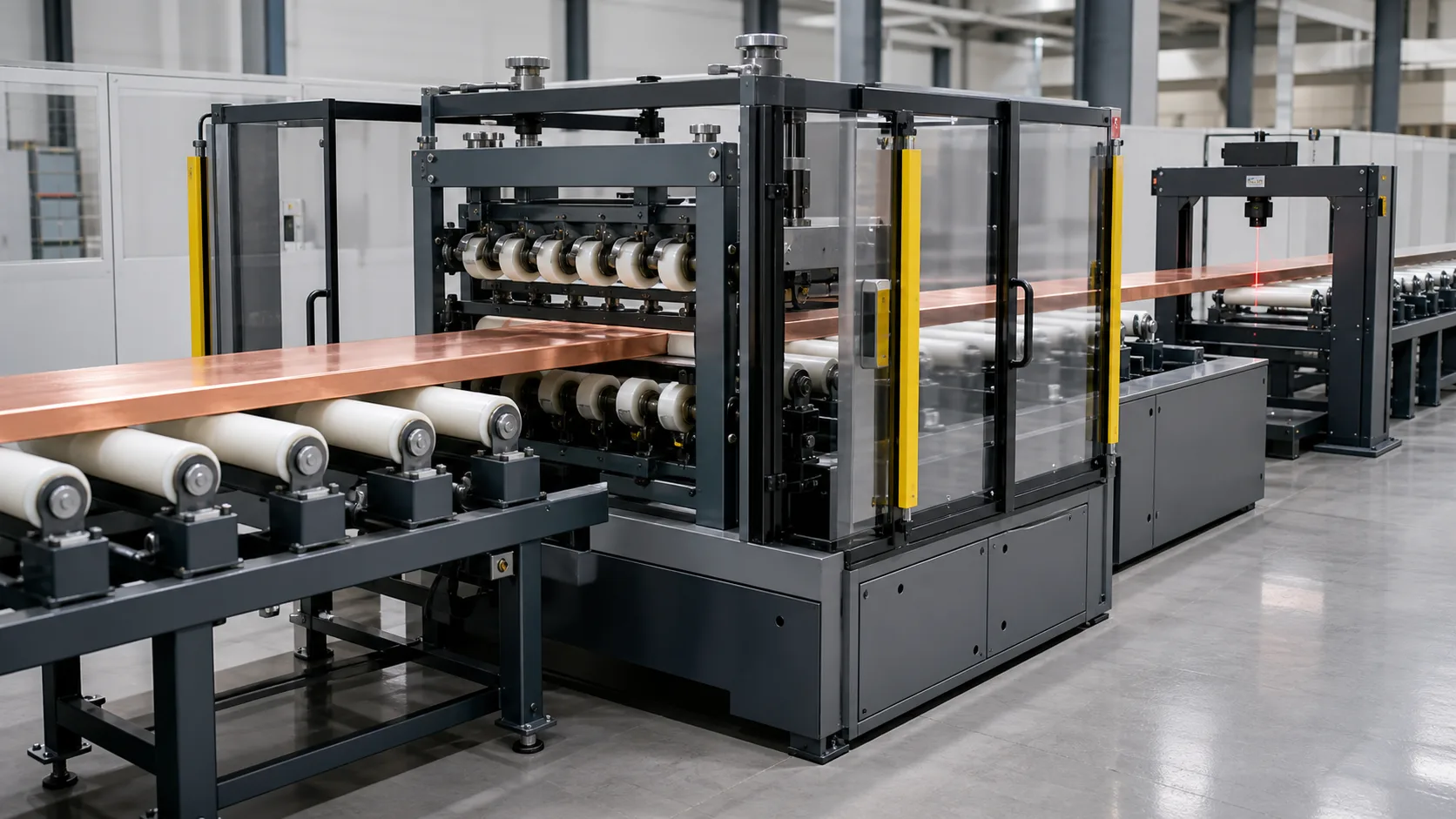
*Engineering concept illustration of a solid rectangular copper busbar entering a protected roll-straightening and measurement line. It is not a customer-site photograph or performance claim. Actual roll geometry, संपर्क दबाव, सहायता, force and acceptance limits require the controlled material and part specification.*
Define the Busbar Family and Process Route
| Family or State | Main Difference | Route on This Page |
|---|---|---|
| Raw copper flat bar | Straight stock before holes, slots and bends | Primary continuous-straightening scope |
| Punched or cut blank | Features can alter stiffness and restrict contact | Feature-aware measurement and point correction |
| Tin-, चाँदी- or nickel-plated busbar | Coating and contact lands need qualified protection | Low-marking tooling and surface inspection |
| Aluminium busbar | Different material, springback and surface behavior | Separate qualified recipe family |
| Laminated flexible busbar | Layered construction and designed flexibility | Outside solid-bar correction logic |
| Intentionally bent or twisted busbar | Drawing geometry contains flat, किनारा, offset or torsion bends | Forming and angle-verification route |
| Assembled busbar or busway | समर्थन, joints and insulation define the system geometry | Assembly inspection; do not press as loose stock |
| Generic steel flat bar | Different material and functional surface requirements | Separate flat-bar solution |
KME publicly lists copper flat bars for switchgear, power distribution, transformers and electrical machines, with multiple geometries and material conditions. ABB's busbar-system guidance treats flat copper busbars as current-carrying parts whose section, supports and short-circuit loading belong to the electrical design. These facts make material identity, finished interfaces and downstream use part of the straightening input.
Freeze the Process Stage
Incoming Mill Bar
Straightening raw stock can improve stable feeding into cutting and punching. The incoming bundle should be separated by alloy, temper, section and supplier condition. Do not create one pressure recipe for every copper bar merely because the cross-section is rectangular.
Before Punching and Cutting
Longitudinal straightness and twist affect clamp engagement, reference-edge tracking and feature position. Boschert states that copper-bar punching requires rigid processing, accurate clamping and support on both sides of the punch area to avoid twisting and bending. Use this as evidence for process integration, not as a StraighteningTech performance guarantee.
After Punching, Cutting or Machining
Holes, slots, notches and local section loss can change stiffness and create protected zones. Measurement must not interpret the feature itself as surface error, and press points must not bridge or distort a hole pattern.
Before or After Plating
Pre-plating correction avoids damaging a finished coating but must preserve the stock allowed for later finishing. Post-plating correction needs a qualified contact-pressure and marking trial plus inspection of plated joint areas.
Intentional Busbar Forming
Flat bending, edge bending, offsets and twist bends are controlled forming operations. Stierli-Bieger publicly describes busbar angle measurement, springback compensation, edge bending and twist tooling. That evidence supports a dedicated forming route; an intentionally formed conductor must not be straightened back to zero.
Measure Three Geometry Modes Separately
Flatwise Bow
Flatwise bow is deviation normal to the broad face. Because the bending stiffness is lower in this direction for many rectangular sections, रिक्ति का समर्थन करें, self-weight and probe force can significantly change the reading.
Edgewise Bow
Edgewise bow is deviation normal to the narrow edge. It requires a stable lateral datum and adequate support against bar roll. A bar can pass a broad-face check and still fail edge alignment in a cabinet or assembly.
मोड़
Twist is change of section angle along the bar. Broad-face height at one sensor cannot fully distinguish twist from bow, support-height error or local thickness variation. Use paired face/edge references or another qualified angular method.
The measurement plan should define:
- alloy, temper, अनुभाग, length and grain/rolling direction where relevant;
- axial origin, end condition and excluded end lengths;
- broad-face and edge datums;
- support number, अंतर, roller condition and height;
- feature masks for holes, slots, notches and offsets;
- plated or finished contact-land map;
- temperature, cleaning and stabilization condition;
- repeatability after full release and repositioning;
- correlation with the downstream fixture or final inspection gauge.
Read shaft straightness vs runout vs TIR for the general distinction between stationary geometry and rotating indication. A busbar is normally a supported profile, not a rotating part.
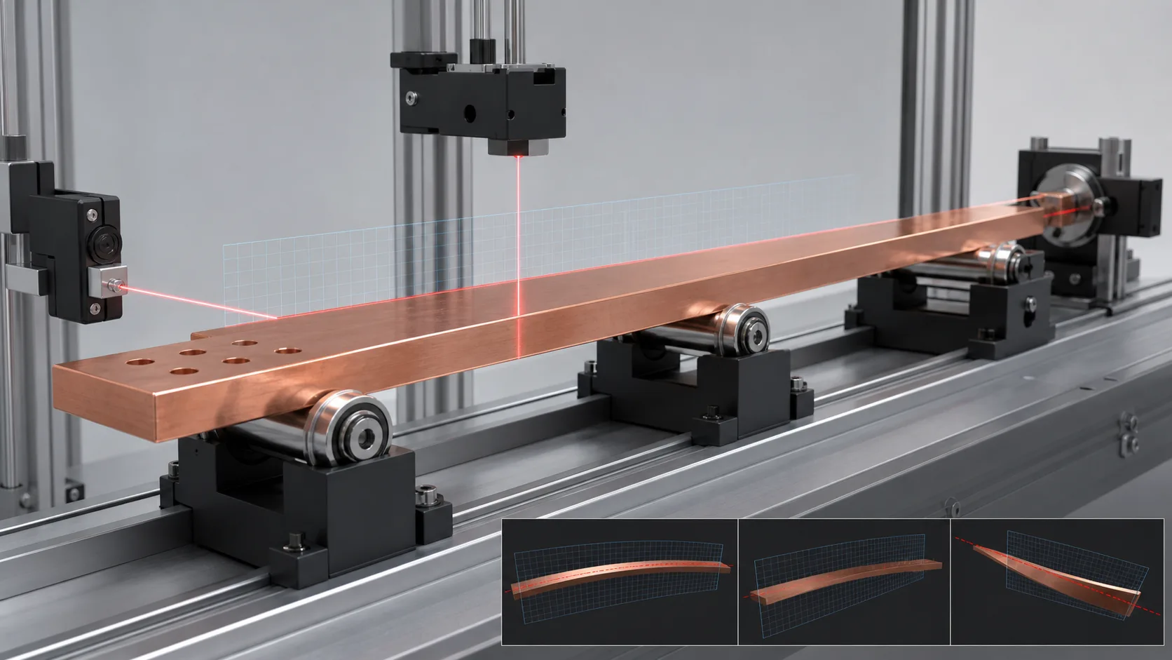
*Engineering concept illustration of three-mode measurement around a simple rectangular section. It is not a prescribed gauge layout. Actual sensor paths, रिक्ति का समर्थन करें, feature masks and acceptance bands require the controlled drawing and customer-gauge correlation.*
Classify the Signal Before Applying Force
| Observed Signal | Possible Cause | Required Route |
|---|---|---|
| Smooth broad-face deviation repeated after support reset | Flatwise bow | Candidate for qualified roll or point correction |
| Smooth edge deviation repeated after repositioning | Edgewise bow | Side-direction correction with orientation control |
| Face and edge references rotate along the length | मोड़ | Torsion-specific measurement and correction |
| Sharp change near a hole or notch | Local process distortion or feature-mask error | Feature inspection before correction |
| Signal changes with support spacing | Sag, roller-height error or unstable bar roll | Freeze support condition and repeat measurement |
| Local high spot on a finished face | गड़गड़ाहट, काटने का निशान, plating build-up or contamination | Surface/feature route, not centerline correction |
| Geometry matches drawing offsets or twist | Intentional forming | Preserve nominal geometry; do not straighten to zero |
| Joint lands align poorly after assembly | Part geometry, fixture, support or tolerance-stack error | Assembly diagnosis before modifying the conductor |
| Hole pattern is distorted | Punching or local yielding | Feature inspection; straightening does not restore hole geometry automatically |
Protect Conductive and Finished Surfaces
Default Protected or Review Zones
- plated, polished or specified low-resistance joint lands;
- छेद, slots, notches, countersinks and threaded features;
- narrow edges where concentrated contact can roll or dent material;
- printed, stamped or traceability markings;
- insulation interfaces, sleeves and coated regions;
- local bends, offsets and twist features required by the drawing;
- गड़गड़ाहट, दरारें, delamination, severe dents or overheated areas pending disposition.
Potentially Approved Contact Zones
- clean unfinished broad faces selected by process engineering;
- replaceable polymer, fibre or profiled pads qualified for pressure and marking;
- scrap-end or later-trimmed regions when the process plan explicitly permits contact;
- non-functional surfaces demonstrated by representative contact trials.
“Non-marking” is not an absolute claim. The contact trial should define acceptable indentation, scratch, coating transfer, contamination and electrical-surface inspection criteria.
Choose the Correction Architecture
Multi-Roll Straightening
A multi-roll line can suit recurring raw-stock families with controlled incoming curvature and stable section. The recipe should define roll penetration, अभिविन्यास, contact material, guidance and pass strategy by alloy and temper. Fully released measurement remains the acceptance signal.
Point-Press Straightening
A horizontal or vertical press can suit local bends, finished blanks, mixed batches or end zones. Broad replaceable supports can distribute pressure, but the approved load path must avoid holes, slots, plated lands and unsupported edges.
Edgewise and Torsion Correction
Edgewise bow and twist need dedicated restraint and sensing. Turning a bar between repeated flatwise presses without classifying the mode can introduce a second error or damage the surface.
Forming Cell
When the target contains designed bends, offsets or rotation, use a forming recipe with angle and springback verification. Do not combine straightness acceptance and formed-angle acceptance into one zero-reference measurement.
Read press straightening vs roller straightening before choosing the correction family.
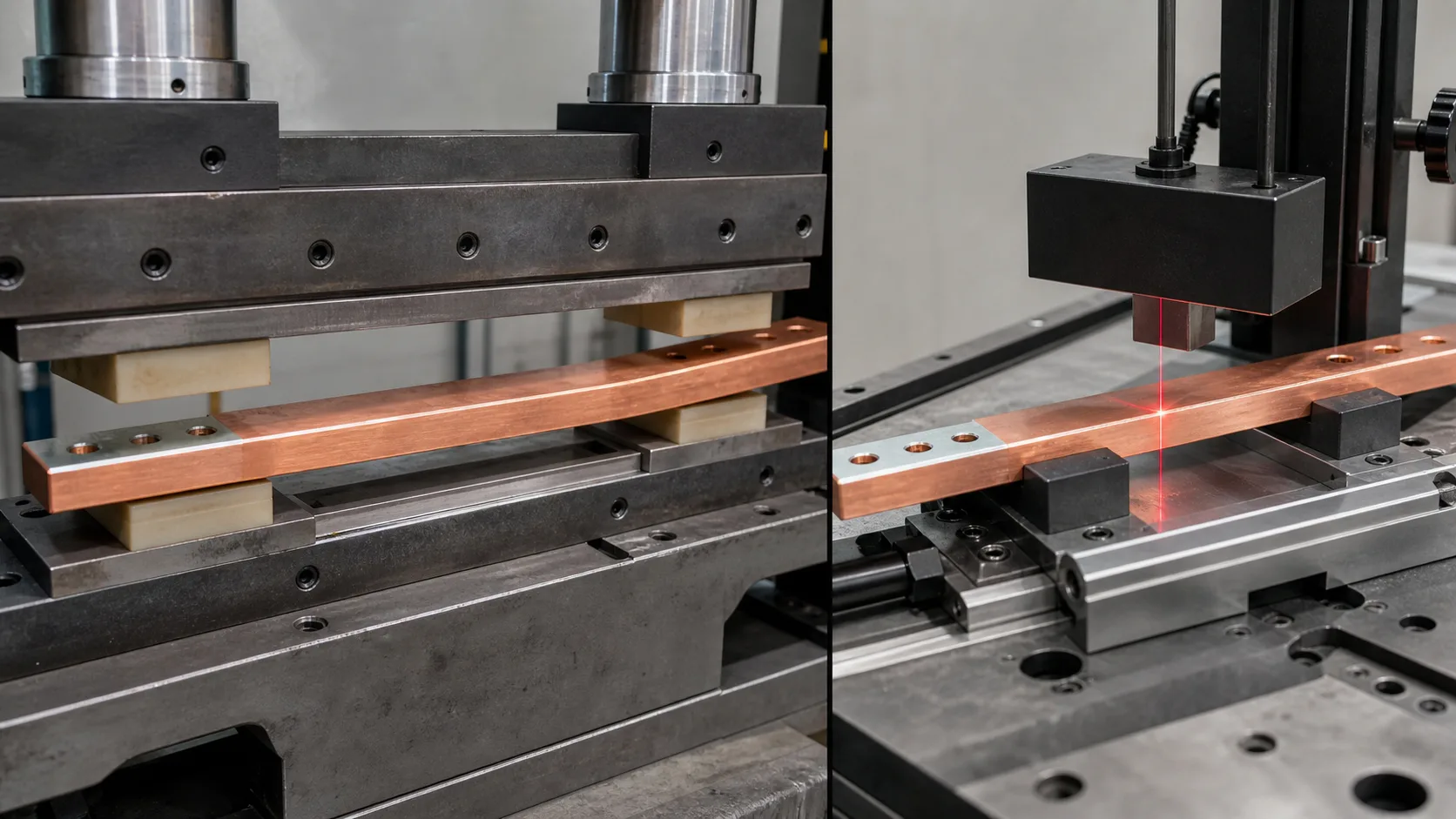
*Engineering concept illustration of feature-aware point correction using broad replaceable pads, followed by released measurement. It is not a universal machine layout. Actual force, अवधि, tooling material, displacement and surface limits require project engineering and sample trials.*
Integrate Feeding Without Adding New Error
The handling concept should include:
- level entry and exit conveyors with low-marking rollers;
- guides that control edge position without galling copper;
- clamps that do not slip, twist or indent the bar;
- feature-aware indexing for holes, slots and cut ends;
- controlled unloading so long flexible sections do not sag or collide;
- cleaning to prevent embedded chips and oxide from marking surfaces;
- recipe interlocks for alloy, temper, section and process stage;
- safe recovery after a jam or interrupted correction cycle.
Verify the Released Busbar
- Identify alloy, temper, अनुभाग, process stage and traceability.
- Confirm straight nominal geometry versus designed bends or offsets.
- Inspect and clean measurement and approved contact zones.
- Load the bar on the frozen support and orientation setup.
- Measure flatwise bow, edgewise bow and twist separately.
- Mask legitimate holes, slots and formed features.
- Classify geometry error, surface/feature defect and setup error.
- Select roll, point press, टोशन, forming, reject or engineering-review route.
- Apply only the bounded correction assigned to the approved zone and mode.
- Fully release and stabilize the bar.
- Remeasure under the same datum and support condition.
- Complete surface, plating, feature and downstream-fixture checks.
- Store the before/after profile, व्यंजन विधि, inspection and disposition.
Configure the Cell Around the Qualified Family
| कोशिका कार्य | Copper-Busbar Requirement |
|---|---|
| पहचान | Alloy, temper, width, thickness, लंबाई, process stage and traceability |
| हैंडलिंग | Low-marking rollers, edge guidance, feature indexing and controlled unload |
| माप | Flatwise bow, edgewise bow, मोड़, ends and masked feature zones |
| Classification | Continuous curvature, स्थानीय गुत्थी, मोड़, sag/setup error and designed geometry |
| सुधार | Multi-roll, point press, side correction, torsion or forming route |
| सुरक्षा | Conductive faces, plating, छेद, slots, edges, markings and insulation zones |
| सत्यापन | Released geometry plus surface, feature and downstream-fixture checks |
| डेटा | Before/after profiles, स्थापित करना, force/displacement, inspection and disposition |
Proposal Inputs We Need
Send the following before equipment selection:
- controlled part and raw-stock drawings;
- copper/aluminium alloy, temper and material certificate requirements;
- width, thickness, length and family mix;
- incoming flatwise, edgewise and twist error distribution;
- प्रक्रिया चरण: raw, काटना, punched, machined, formed, plated or assembled;
- hole, slot, notch, bend, offset and protected-contact maps;
- सतह खत्म, plating and acceptable marking criteria;
- final straightness and formed-geometry definitions;
- line takt, feed direction and upstream/downstream interfaces;
- ग्राहक गेज, fixture, report and traceability requirements;
- प्रतिनिधि अच्छा, marginal and reject samples.
Sample-Test Acceptance Before Production Release
The sample trial should cover the alloy, temper, अनुभाग, process-stage and error-mode envelope. It should verify support repeatability, flatwise/edgewise/twist classification, स्प्रिंग बेक, feature avoidance, contact marking, released geometry and downstream fixture or electrical-surface inspection.
उपयोग straightening sample test and acceptance guide to freeze the test matrix and evidence package.
Engineering Boundary
Straightening can correct approved geometric error in suitable solid busbar. It does not restore distorted holes, repair cracks, renew damaged plating, remove contamination, prove joint resistance, redesign short-circuit supports or certify the completed switchgear assembly.
Machine force, roll layout, समर्थन अवधि, accuracy, समय चक्र, overbend and iteration count are proposal outputs. They must come from the controlled material family, प्रक्रिया चरण, drawings, samples and customer gauge—not from a competitor specification table.
Request a Copper Busbar Straightening Review
Send the material and section table, drawings, process route, protected-contact map, incoming-error profiles and representative samples. We will return a proposed datum and support model, correction architecture, tooling-protection plan, sample-test matrix and equipment configuration for review.