
Sähkötyökalun jatkotanko voi näyttää yksinkertaiselta hoikalta akselilta, mutta sen kaksi päätä suorittavat yleensä erilaisia tehtäviä. Toinen pää on liitetty porakoneeseen tai iskuvääntimeen; toinen pitää tai ajaa vähän tai lisävarustetta. Kuusikulmaiset osat, pitävät urat, pistorasiat, reiät ja paikallinen lämpökäsittely tekevät työkappaleesta epäsymmetrisen ja jättävät vain rajallisia mittaukseen sopivia vyöhykkeitä, tuki ja paina yhteyttä.
Luotettavan sähkötyökalun jatkotangon oikaisuratkaisun on siksi aloitettava piirustuksesta ja toimintamittarista. Sen on määritettävä peruspiste, erillinen akselin mutka päätyliitäntävirheestä, suojaa kriittiset pinnat ja tarkista tulos jokaisen korjauksen jälkeen. Sen ei pitäisi soveltaa yhtä toleranssia, sykliaika tai automaatiokonsepti jokaiseen 1/4 tuuman laajennukseen.
Tunnista työkappale ennen koneen valintaa
Todellisessa projektikuvassa näkyy useita pitkiä sähkötyökalujatkoja, joilla on eri päätygeometriat. Ne eivät ole onttoja hihoja, eikä niitä pidä sekoittaa autojen moottorien kiertokangiin.
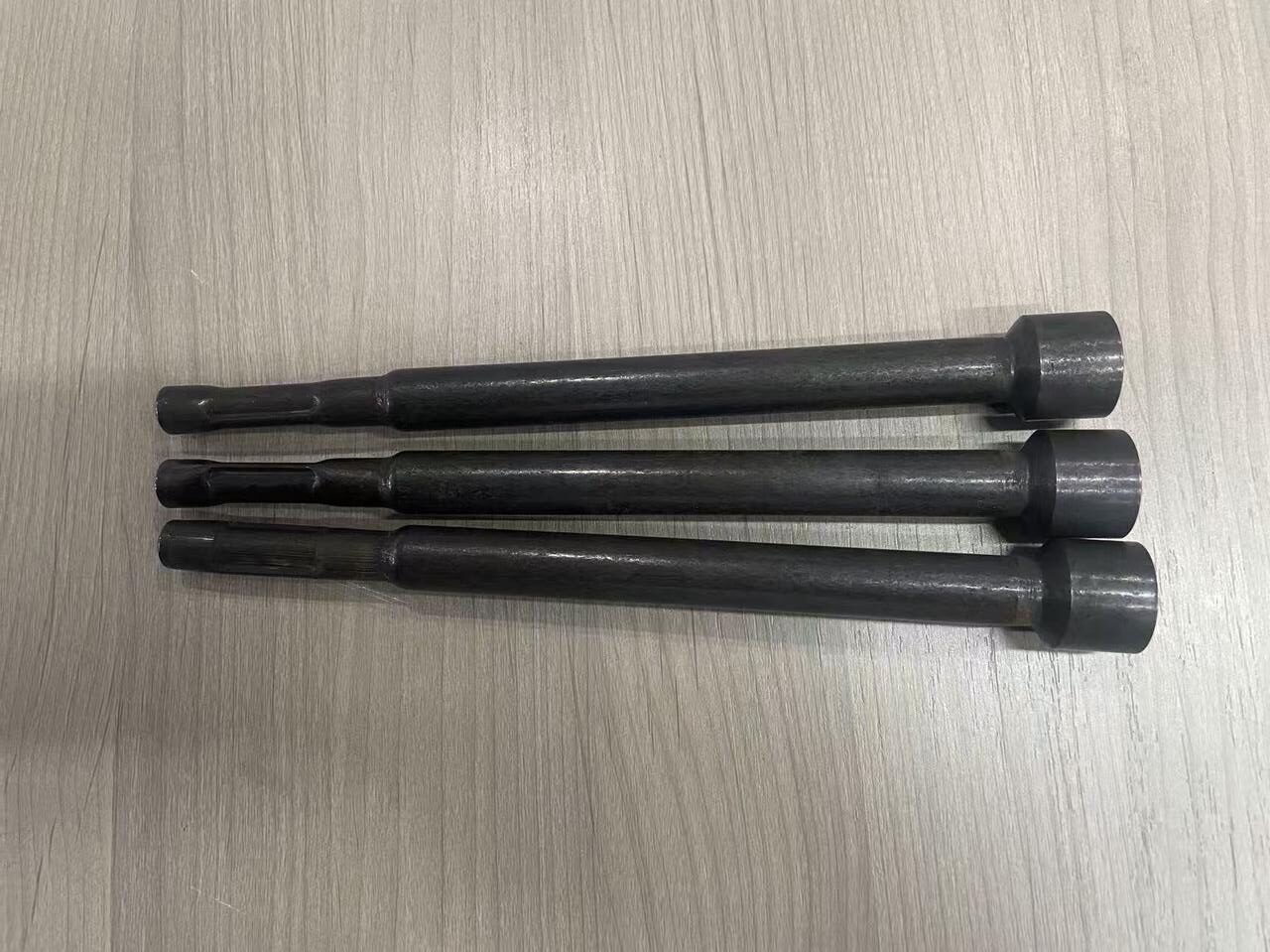
Viralliset työkaluvalmistajat käyttävät termejä, kuten universaali terän pidike ja 1/4-tuuman kuusiovarren jatke liittyville tuoteperheille. Nämä nimet auttavat määrittämään sovelluksen, mutta ne eivät todista, että jokaisella laajennuksella on sama käyttöliittymä, materiaalia tai vastaanottotapaa. Asiakaspiirustus pysyy ohjaavana lähteenä. A hollow sleeve-type variant is covered separately in the kiertokangen hihan suoristusratkaisu.
Ennen kannattavuustestausta, tunnistaa:
| Ominaisuus | Miksi oikaisulla on merkitystä |
|---|---|
| Sisääntulo kuusiovarsi | Voi määrittää sähkötyökalun akselin, mutta se ei ole automaattisesti sopiva pyörivä mittauspinta |
| Lähtöpidike tai pistorasia | Toiminnallinen huojunta voi riippua sen porauksesta, kiinnitysominaisuus ja kokoonpanon kunto |
| Tasaiset akselivyöhykkeet | Potentiaalimittaus, tuki- tai korjauspaikat, jos piirustus sallii yhteydenoton |
| Ura, ristireikä tai siirtymä | Luo paikallisen jäykkyyden muutoksen ja voidaan jättää puristamatta |
| Lämpökäsitelty alue | Muuttaa takajousta ja halkeamisriskiä verrattuna akselin ytimeen |
| Pinnoite tai viimeistelty pinta | Rajoittaa sallittua anturia, tuki ja lyöntiyhteys |
Raportoidut projektisyötteet eivät ole yleisiä määrityksiä
Sivuston aikaisemmassa artikkelissa kerrottiin a 6.35 mm × 200 mm työkappale ja lopullinen kohde 0.2 mm. Näitä arvoja käsitellään tässä vain raportoituina projektisyötteinä. Käytettävissä oleva lähde ei määrittele, onko 0.2 mm tarkoittaa suoruutta, säteittäinen juoksu, ilmoitettu lopputulos yhteensä, koaksiaalisuus tai toiminnallinen kärjen huojunta. Se ei myöskään tunnista peruspistettä, mittauspaikat tai lopullinen mittari.
StraighteningTech vahvistaa ehdotuksen varsinaisen piirustuksen ja edustavien näytteiden perusteella. Kaupallisen takuun tulee kattaa vain testattu työkappaleperhe, saapuvien ehtojen ikkuna ja sovittu hyväksymistapa.
Suoruus, Runout ja toiminnallinen huojunta
Nämä ominaisuudet liittyvät toisiinsa, mutta eivät vaihdettavissa keskenään:
| Ominaista | Kysymys Se Vastaa | Pakollinen määritelmä |
|---|---|---|
| Suoruus | Kuinka paljon valittu akselilinja tai pinta poikkeaa ihanteellisesta suorasta? | Valvottu alue, arvioinnin pituus ja perussääntö |
| Radial runout/TIR | Kuinka paljon pinta vaihtelee, kun osa pyörii määritellyn akselin ympäri? | Pyörimispäivämäärä, anturin sijainti ja suodatus |
| Koaksiaalisuus | Kuinka hyvin tulo- ja lähtöakselit kohdistuvat? | Molemmat akselit ja sovellettavat piirustusvaatimukset |
| Toimiva heilutus | Kuinka paljon asennettu pääterä tai lisälaite liikkuu pyörimisen aikana? | Mestari työkalu, sitoutumisen syvyys, testinopeus ja lukupaikka |
Osalla voi olla hyväksyttävä sileän akselin lukema, mutta se silti epäonnistuu ulostulopitimessä, jos päätyosa on epäkesko tai asennettu väärin. Päinvastoin, vaihteleva hex-verhokäyrä voi tuottaa epävakaan koetinsignaalin, vaikka toimintaakseli on hyväksyttävä. The machine measurement and the customer's final gauge must therefore be correlated during sample testing.
Oikaisuehdotusta varten tarvittavat tiedot
| Projektin syöttö | Pakollinen yksityiskohta |
|---|---|
| Piirustus | Tarkistus, mitat, perustiedot ja ohjatut ominaisuudet |
| Tuotteen identiteetti | Jatkopalkki, bitin pidike, adapteri tai muu työkaluperhe |
| Lopeta rajapinnat | Hex standardi, pidike/kanta geometria, kestänyt, ura, reikä ja pidätysmenetelmä |
| Materiaali ja lämpökäsittely | Ytimen kovuus, paikallisesti kovettuneet alueet ja pinnoite |
| Valmistusreitti | Muodostaminen, koneistus, lämpökäsittely, hiominen, pinnoitus ja kokoonpanojärjestys |
| Tuleva muodonmuutos | Taivutuksen suuruus, suunta ja aksiaalijakauma edustavista näytteistä |
| Lopullinen hyväksyntä | Suoruus, TIR, koaksiaalisuus tai toiminnallinen huojunta peruspisteen ja mittarin kanssa |
| Yhteydenpitorajoitukset | Pinnat joissa tuet, anturit ja puristuslävistin voivat koskettaa tai olla koskettamatta |
| Tuotantolaajuus | Varianttivalikoima, lähtötavoite, lataustapa, vaihto ja jäljitettävyys |
Suositeltu suljetun silmukan oikaisuprosessi
1. Tunnista ja suuntaa jatkopalkki
Solu tunnistaa valitun muunnelman ja vahvistaa epäsymmetristen päiden suunnan. Ruokinta voi olla manuaalinen, tarjotinpohjainen, kuljettimeen perustuva tai kehitetty validoidun irtotavarasyöttöjärjestelmän ympärille. Satunnaista bulkkikuormausta ei oletetaan ennen kuin todellinen osaperhe on läpäissyt sotkeutumisen, päällekkäisyydet ja suuntakokeet.
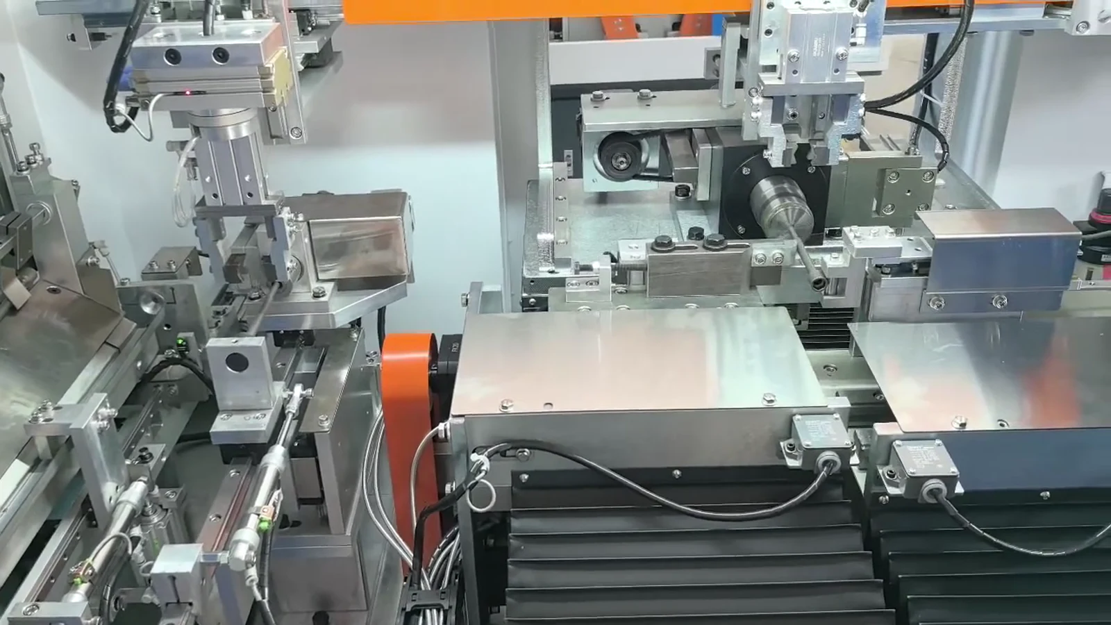
Yllä oleva kuva on kehys todellisesta projektivideosta. Se tukee automaattisen siirto-/suuntauslaitteiston läsnäoloa esitellyssä asemassa. Se ei sinänsä todista satunnaista irtotavaraa tai a 100% suuntautumisnopeus.
2. Määritä toiminnallinen peruspiste
Työkappale on sijoitettu keskikohtiin, hyväksyttyjä lehtiä, ohjattu kuusiorajapinta tai erityiset kiinnikkeet piirustuksen mukaan. Tukien on toistettava tarkastuslogiikka pakottamatta ohutta akselia väärään suoraan tilaan.
3. Mittaa hyväksytyt kuilualueet
Jatke pyörii tai indeksoi samalla, kun anturit keräävät lukemia määritellyissä aksiaalisissa paikoissa. Mittaussuunnitelma ei sisällä uria, ristiin reikiä, hylsyn reunat ja muut kuin pyöreät vyöhykkeet, ellei käytetä validoitua profiilikohtaista menetelmää. Ohjain muodostaa saapuvan taivutuskäyrän ja erottaa toistettavat geometriasignaalit keskilinjan siirtymästä.
4. Valitse tukijänne ja korjauspiste
Säädin valitsee hyväksytyn tukivälin ja puristusasennon. Työkalu ja ohjelmisto rajoittavat kosketusta vetokulmien kanssa, pidätysura, pistorasia huuli, poraus ja muut kielletyt ominaisuudet.
5. Käytä vaiheittaista pistekorjausta
Puristin käyttää hallittua siirtymää tai voimaa valitussa paikassa. Korjaus on asteittainen ohuiden akselien vuoksi, lämpökäsitellyillä vyöhykkeillä ja äkillisillä osien muutoksilla voi olla erilainen takaisku. Suurin voima, iskun ja iteroinnin rajat estävät hallitsemattoman toistuvan painamisen.
6. Mittaa uudelleen käyttämällä samaa peruspistettä
Jokaisen painalluksen jälkeen, järjestelmä mittaa työkappaleen uudelleen muuttamatta hyväksymisohjetta. Toinen korjaus tehdään vain, kun jäännösvirhe on hyväksytyn prosessiikkunan ulkopuolella.

7. Tarkista ja pura
Lopullista konelukemaa verrataan piirustuskohtaiseen sääntöön. Missä toiminnallisella huojunnalla on merkitystä, the sample study also correlates the machine result with the customer's master tool or final gauge. Automaattinen erottelu, tulosten tallennus ja linjaviestintä sisältyvät vain, jos ne on määritelty tilatussa kokoonpanossa.
Todellinen sähkötyökalun jatkotangon oikaisuvideo
Seuraava julkinen projektivideo näyttää todellisen laajennuspalkin, siirtolaitteisto ja automaattinen oikaisuasema. Se tukee työkappaleen käyttöä ja näkyvää prosessisekvenssiä; se ei todista universaalia tarkkuutta, syklin aika, tuotto tai työn tulos.
Työkalu ja pintasuojausstrategia
"Ei vaurioita" on hyväksymisvaatimus, ei yleinen lupaus. Varsinaisen työkalun on vastattava sallittuja kosketusvyöhykkeitä, kovuus, pinnoite ja päätygeometria.
| Työkaluelementti | Suunnittelukysymys |
|---|---|
| Lopun paikannus | Toistaako se toiminnallisen akselin merkitsemättä tai vääristämättä kuusio-/pidikeliitäntää? |
| Tukee | Kantavatko ne korjauskuorman hyväksytyillä sileillä vyöhykkeillä? |
| Paina rei'itys | Onko sen säde/profiili yhteensopiva akselin halkaisijan kanssa, kovuus ja sallittu pintapaine? |
| Mittausanturi | Lukeeko se akselin siirtymän kuusiokulman sijaan, urien reunat tai hylsyn geometria? |
| Vaihtosarja | Onko jokainen variantti mekaanisesti avattu ja sovitettu oikeaan reseptiin? |
Ohuille tai karkaistuille pidennyksille, toteutettavuustestin pitäisi luoda turvallinen korjausikkuna. Jos piirustus tai asiakkaan laatusuunnitelma edellyttää halkeamien tarkastusta, pinnan tarkastus tai toiminnallinen vääntömomentin testaus, nämä tarkastukset on sisällytettävä validointi- ja tuotantosuunnitelmaan.
Automaatio valitaan ruokintakokeiden jälkeen
| Automaatiotaso | Sopiva tilanne | Tyypillinen laajuus |
|---|---|---|
| Manuaalinen lataus | Monia muunnelmia, pienempi määrä tai toteutettavuusaste | Kuljettaja kuormittaa; kone mittaa, korjaa ja vahvistaa |
| Lokeron tai lehden syöttö | Vakaa suunta ja hallittu esitys | Ohjattu ruokinta, automaattinen sykli ja tuloksen näyttö |
| Validoitu irtotavaran ruokinta | Suuri tilavuus ja osat, jotka eivät ole sotkeutuneet tai menevät päällekkäin | Syöttölaite, pakoon, suuntatarkistukset ja hylkäys-/palautuslogiikka |
| Integroitu linja | Vakaa perhe, jossa ylä- ja loppupään liitännät | Puskuri, käsittelyä, tulosten erottelu ja sovittu viestintä |
| Jäljitettävä solu | Osatason tietueet vaaditaan | Osan tunnus, resepti, mittaus- ja korjaushistoria |
Jaksoaika on mitattava lopullisessa konfiguraatiossa. Riippuu pituudesta, mittausasennot, korjaustoistojen määrä, ruokintamenetelmä, versiotarkistukset ja tietovaatimukset. Lyhyt videoleike tai yksi onnistunut näyte ei pysty vahvistamaan tuotantokapasiteettia.
Näytetesti- ja hyväksymissuunnitelma
Edustavia näytteitä
- jokainen ehdotukseen sisältyvä päätyliitäntä ja pituus;
- normaalit osat ja näytteet lähellä odotettua sisääntulevan taivutuksen rajaa;
- jokaista materiaalia, lämpökäsittelyn ja pinnoituksen kunto;
- osia useammasta kuin yhdestä tuotantoerästä, joissa takaisku voi vaihdella;
- tarpeeksi näytteitä toistettavuuden arvioimiseksi, ei vain yhtä korjattua osaa.
Todiste tallennettavaksi
| Tallentaa | Hyväksymistodistus |
|---|---|
| Osan identiteetti | Piirustusversio, variantti, erä- ja prosessireitti |
| Tuleva mittaus | Datum, mittausasennot, mittari ja muodonmuutoskäyrä |
| Työkalujen konfigurointi | Etsijät, tukiväli, lyönti- ja kielletyt kosketusalueet |
| Korjaushistoria | asema, voima/siirtymä ja iteraatioiden määrä |
| Lopullinen konetulos | Sama peruspiste ja menetelmä, jota käytetään tulevaan mittaukseen |
| Mittarikorrelaatio | Comparison with the customer's final or functional gauge |
| Pinta/päätytarkastus | Marks, halkeamat ja käyttöliittymän kunto sovitun säännön mukaan |
| Syklin tarkkailu | Vahvistetun kokoonpanon mitattu aika |
Yleiset vikatilat ja säätimet
| Vikatila | Todennäköinen syy | Ohjaus |
|---|---|---|
| Epävakaa lukema kuusiokulmassa tai urassa | Anturi noudattaa profiiligeometriaa | Siirry hyväksytylle sileälle alueelle tai vahvista profiilikohtainen mittaus |
| Akseli kulkee, mutta pidike huojuu | Väärä peruspiste tai epäkeskopää | Lisää käyttöliittymäakselin ja funktionaalisen mittarin korrelaatio |
| Merkitse heksaan, ura tai hylsy | Väärä tuen/rei'in sijainti | Suojaa kielletyt vyöhykkeet mekaanisesti ja ohjelmisto estää |
| Halkeama korjauksen jälkeen | Ylimääräinen mutka, paikallinen kovettuminen tai sopimaton jänneväli | Vaiheen korjaus, aseta rajat ja lisää vaadittu halkeamien tarkastus |
| Variantti latautuu taaksepäin | Päädyn geometriaa ei eroteta luotettavasti | Lisää poka-yoke, läsnäolon/suunnan tunnistus ja hylkäyslogiikka |
| Tulos muuttuu vaihdon jälkeen | Työkalu ja resepti eivät täsmää | Avaa työkalut ja tarkista valittu versio ennen syklin aloittamista |
Mitä tämä ratkaisu ei lupaa ilman vahvistusta
- yksi kiinteä tarkkuus jokaista 1/4 tuuman laajennusta kohden;
- jokaisen tulevan mutkan tai lämpökäsittelytilanteen korjaus;
- nolla pintajälkiä, nolla huojuntaa tai nolla halkeamisriskiä;
- yleinen 10–15 sekunnin sykli tai kiinteä tuottoprosentti;
- satunnainen massasyöttö tai täydellinen suunta jokaiselle geometrialle;
- yksi kuljettaja valvoo ilmoitettua määrää koneita;
- automaattinen jäljitettävyys, MES-liitäntä tai linjaintegrointi, ellei tilauksesta;
- että raportoi 0.2 mm:n tavoite on jo saavutettu vakaassa tuotannossa.
Aiheeseen liittyvät oikaisulaitteet ja sovellukset
Viereiseen konekokoonpanoon, tarkista ZD300 iskuruuvimeisselin oikaisukone. Laajempaan työkappaleperheeseen, katso Työkalujen suoristamisratkaisut. Nämä linkit tarjoavat laitteet ja sovelluskontekstit; oikea konfiguraatio riippuu edelleen todellisesta piirustuksesta ja näytetestistä.
Tiedot lähetettäväksi ehdotusta varten
Once the power tool extension bar process questions are answered, two pages usually shorten the shortlist: the suoristimen valinnan esittely ja budjettikuva oikaisukoneeseen.
Lähetä piirustus ja versio, edustavia näytteitä, loppukäyttöliittymän yksityiskohdat, materiaali ja lämpökäsittely, valmistusreitti, sisääntuleva muodonmuutosalue, lopullinen ominaisuus ja perusarvo, mittausmenetelmä, sallitut kosketusalueet, pinta-/halkeamisvaatimukset, lähtötavoite, vaihtoehtovalikoima ja suositeltu lataustapa.
Ota yhteyttä StraighteningTechiin näytepohjaiseen sähkötyökalun jatkotangon oikaisututkimukseen. Ehdotuksessa määritellään mittauspiste, työkalut, korjausrajat, automaation laajuus ja hyväksymistodistus todelliselle työkappaleperheellesi.
Usein kysytyt kysymykset
Onko jokainen 6.35 mm laajennus mitattuna samalla tavalla?
Ei. A 6.35 mm tai 1/4 tuuman liitäntä tunnistaa nimellisen asemaperheen, ei koko dataa ja tarkastusmenetelmää. Lopun geometria, akselin vyöhykkeet, kiinnitysominaisuudet ja piirustusvaatimukset määräävät, miten osa sijoitetaan ja mitataan.
Voiko kone mitata suoraan kuusiovarresta?
Mahdollisesti, mutta yleinen pyöreäakselinen anturi reagoi kuusioprofiiliin. Mittaus hyväksytyllä sileällä vyöhykkeellä on yleensä yksinkertaisempaa. Jos heksan on määritettävä toiminta-akseli, dedicated location or profile-aware measurement must be validated against the customer's gauge.
Voidaanko karkaistuja jatkotankoja puristusoikaista?
Ne voivat olla toteutettavissa, mutta korjausikkuna riippuu materiaalista, kovuus, karkaistu syvyys, saapuva mutka, tukialue ja yhteyspaikka. Edustava näytetestaus ja vaadittu halkeama/pintatarkastus ovat tarpeen ennen takuun antamista.
Minkä tarkkuuden StraighteningTech voi taata?
Vain sovitun työkappaleperheen tulos, saapuvien ehtojen ikkuna, peruspiste ja vastaanottomittari voidaan taata. Arvo aikaisemmasta artikkelista, kilpailijan sivu tai video ei korvaa näytteitä.
Onko koneessa automaattinen syöttö?
Se voi. Manuaalinen, lokero, -lehteä, Irtotavarakäsittely ja integroitu linjakäsittely ovat eri projektialueita. Lopullinen valinta seuraa oikeita ruokinta- ja suuntakokeita.
Terminologian viiteraja
- Wera yleiskärjenpidike: https://www.wera.de/en/tools/895-4-1-universal-bit-holder
- Lämpö 893/1/1 universaali terän pidike: https://www.wera.de/en/tools/893-1-1-universal-bit-holder
- Bosch Professional 1/4 tuuman kuusiovarren jatke: https://www.bosch-professional.com/middle-east/en/extension-bars-for-spade-bits-1-4-inch-quick-change-2867392-ocs-ac/
Nämä viralliset viittaukset tukevat vain terminologiaa. Ne eivät tarkoita, että kuvassa oleva työkappale on näiden merkkien valmistama tai että heidän tuotetiedot määrittävät StraighteningTech-projektin.