
Pitkä kuulanasta ei ole tavallinen pyöreä tanko, eikä se ole täydellinen raidetankokokoonpano. Siinä yhdistyvät hoikka varsi ja erittäin kuormitettu kuulapää, siirtymäsäde ja, valmistusvaiheesta riippuen, asuntoja, kartiomainen, kierteet tai viimeistellyt laakeripinnat. Oikaisumenetelmän on korjattava käyttökelpoinen varsi rullaamatta tai painamatta toiminnallisia vyöhykkeitä, joita ei ole suunniteltu kosketukseen.
Tästä syystä, pitkä kuulanasta oikaisuratkaisu alkaa piirtämisestä ja valmistusreitistä. Telaprosessi voi olla tehokas riittävän tasaisen varren ja jakautuneen kaarevuuden saavuttamiseksi; mitatun pisteen korjaus voi olla turvallisempaa, kun käytettävissä oleva rullan kosketuspituus on lyhyt tai kun kappaleessa on valmiita ominaisuuksia, jotka vaativat valikoivaa kosketusta.
Ball Stud, Pallonivel ja raidetanko ovat eri tuotteita
ZF kuvaa alustan kuulaniveltä teräskuulanastana, joka kulkee kotelon sisällä voideltuun laakerikuppiin. ZF kuvaa myös vetotankoa vivustoksi, joka sisältää sisä- ja ulkopallonivelet, jotka on yhdistetty säätökierteellä. Projektikuvan työkappaleet ovat yksittäisiä pitkiä kuulanastaaihioita, ei kootut pallonivelet tai raidetangot.

Kuva vahvistaa aidot mustapintaiset pitkät pallonastatyyppiset aihiot kuulapäillä ja hoikkailla rungoilla. Se ei määritä teräslaatua, kovuus, mitat, lopullinen geometria tai asiakkaan hyväksyntä.
| Tuote/ominaisuus | Suoristava implikaatio |
|---|---|
| Kylmätaottu kuulanasta-aihio | Mittakaava- ja mittavaihtelut vaikuttavat ruokitukseen, kosketus ja mittaus |
| Pallon pää | On ohjattava tai tyhjennettävä tulevaa laakeripintaa vahingoittamatta |
| Päästä varteen siirtyminen | Suuri geometrinen ja väsymismerkitys; yleensä jätetään pois keskitetystä korjauksesta |
| Tasainen sylinterimäinen varsi | Ehdokasvyöhyke validoidulle jatkuvalle rullakosketukselle |
| Tasainen, kiila tai jakoavainominaisuus | Muuttaa pyörimistä ja voi keskeyttää rullan tuen |
| Kartio tai lanka | Toimiva kokoonpanoalue, joka vaatii suojattua käsittelyä ja mittausmäärittelyä |
| Valmis/karkaistu pinta | Vaatii pintamerkin, jäännösjännityksen ja halkeamien hallinta |
Valitse valmistusvaihe ennen konetta
Sama komponentti voi käyttäytyä hyvin eri tavalla kussakin tuotantovaiheessa.
| Vaihe | Tyypillinen syy suoristukseen | Pääohjaus |
|---|---|---|
| Kylmän takomisen jälkeen | Poista muovauksen/poistamisen aiheuttama mutka ja valmistele koneistusta varten | Mittakaava, mittojen leviäminen ja runsaat mutta määritellyt kosketusvyöhykkeet |
| Karkean koneistuksen jälkeen | Palauta geometria ennen viimeistelyä | Suojaa vertailuhalkaisijat ja säilytä koneistusvara |
| Lämpökäsittelyn jälkeen | Oikea lämpökäsittelyn vääristymä | Kovuusprofiili, takaisku, halkeamisriski ja rajoitettu korjausikkuna |
| Hionnan/kiillotuksen jälkeen | Täytä lopullinen geometria | Erittäin tiukat pintakosketus- ja mittauskorrelaatiovaatimukset |
| Päällystyksen/pinnoituksen jälkeen | Yleensä poikkeuksellinen tapaus | Pinnoitevaurio, vetyyn liittyvä riski ja asiakkaan hyväksyntä |
Projektikuvat näyttävät yhdenmukaisilta tumman kanssa, keskeneräiset aihiot ja telaoikaisuasema. Ne eivät todista tarkkaa valmistusvaihetta. Ehdotuksessa on yksilöitävä tämä vaihe ennen työkalujen tai taattujen tulosten määrittelemistä.
Vaaditut projektisyötteet
| Syöte | Vaadittu yksityiskohta |
|---|---|
| Piirustus | Tarkistus, valvotuille alueille, päivämäärä, toleranssit ja kielletyt kosketusalueet |
| Geometria | Pallon halkaisija, varren halkaisijat, pituus, siirtyminen, asuntoja, kartio ja kierteet |
| Materiaali | Teräslaatu, takomisen kunto ja asiaankuuluvat mekaaniset ominaisuudet |
| Lämpökäsittely | Läpi/induktio/kotelokarkaisu, kovuusprofiili ja käsittelyjärjestys |
| Pinta | Mittakaava, koneistus, hiominen, ammuttu peening, pinnoite ja sallitut merkit |
| Tuleva mutka | Suuruus, suunta ja aksiaalinen jakautuminen edustavien erien välillä |
| Lopullinen ominaisuus | Varren suoruus, johdetun akselin suoruus, lopputulos tai toimiva kokoonpano |
| Tuotantotavoite | Osa sekoitus, ulostulo, lastaus, tarkastusnäytteenotto ja vaihto |
Aikaisemmalla sivulla mainittiin 20–45 HRC-alue ja a 0.2 mm tavoite. Nämä pysyvät raportoituina syötteinä osan todelliseen kuntoon asti, ominaisuus, valvottu pituus ja mitta on dokumentoitu.
Määrittele mitä "0,2 mm:n suoruus" tarkoittaa
| Mahdollinen vaatimus | Pakollinen määritelmä |
|---|---|
| Varren pintaelementin suoruus | Mikä pintaelementti ja ohjattu aksiaalipituus |
| Johdettu varren akselin suoruus | Kuinka akseli rakennetaan mitatuista osista |
| Radiaalinen juoksu | Pyörimispäivämäärä, anturin sijainti ja kulmanäytteenotto |
| Pallosta varteen kohdistus | Pallokeskuksen rakenne ja varren referenssi |
| Kartio/kierre-suhde | Päivämäärä-akseli, toimiva mittari ja hyväksyttävä vaihtelu |
| Suurin rako telineessä | Tukivälit, suuntaus ja mittausmenetelmä |
Kellotaulu tukitelineessä, keskustapohjainen juoksutesti ja koko profiilin suoruusarviointi eivät tuota keskenään vaihtokelpoisia tuloksia. Koneen hyväksynnän tulee käyttää piirustuskohtaista ominaisuutta ja korreloida asiakkaan lopullisen mittarin kanssa.
Kun telan oikaisu on ehdokas
Kaksirullaisia suoristuslaitteita käytetään laajalti pyöreisiin tankoihin, ja valmistajat kuvailevat niitä käyttävän vastakkaisia muotoiltuja rullia tangon taivuttamiseksi ja pyörittämiseksi jatkuvassa prosessissa. Danieli erottaa myös kaksirullan, monitelaiset ja muut tankojen oikaisujärjestelyt erilaisiin sovelluksiin. Nämä periaatteet tukevat prosessiperhettä; ne eivät todista, että jokainen pallonasta voi kulkea saman rullasarjan läpi.
Rullaprosessia arvioidaan, kun:
- varressa on riittävän tasainen kosketuspituus;
- pallon pää, siirtyminen, tasot ja päätykohdat voidaan tyhjentää tai ohjata turvallisesti;
- taivutus jakautuu ja se voidaan korjata validoidulla rullauskäyrällä ja paineella;
- jatkuva pyöriminen/kosketus on sallittu pintaspesifikaatiossa;
- osa ei pääse pakoon, kukko tai hillo, kun pää lähestyy ohjainta;
- näytteiden geometria on hyväksyttävä, pinta- ja metallurginen kunto.
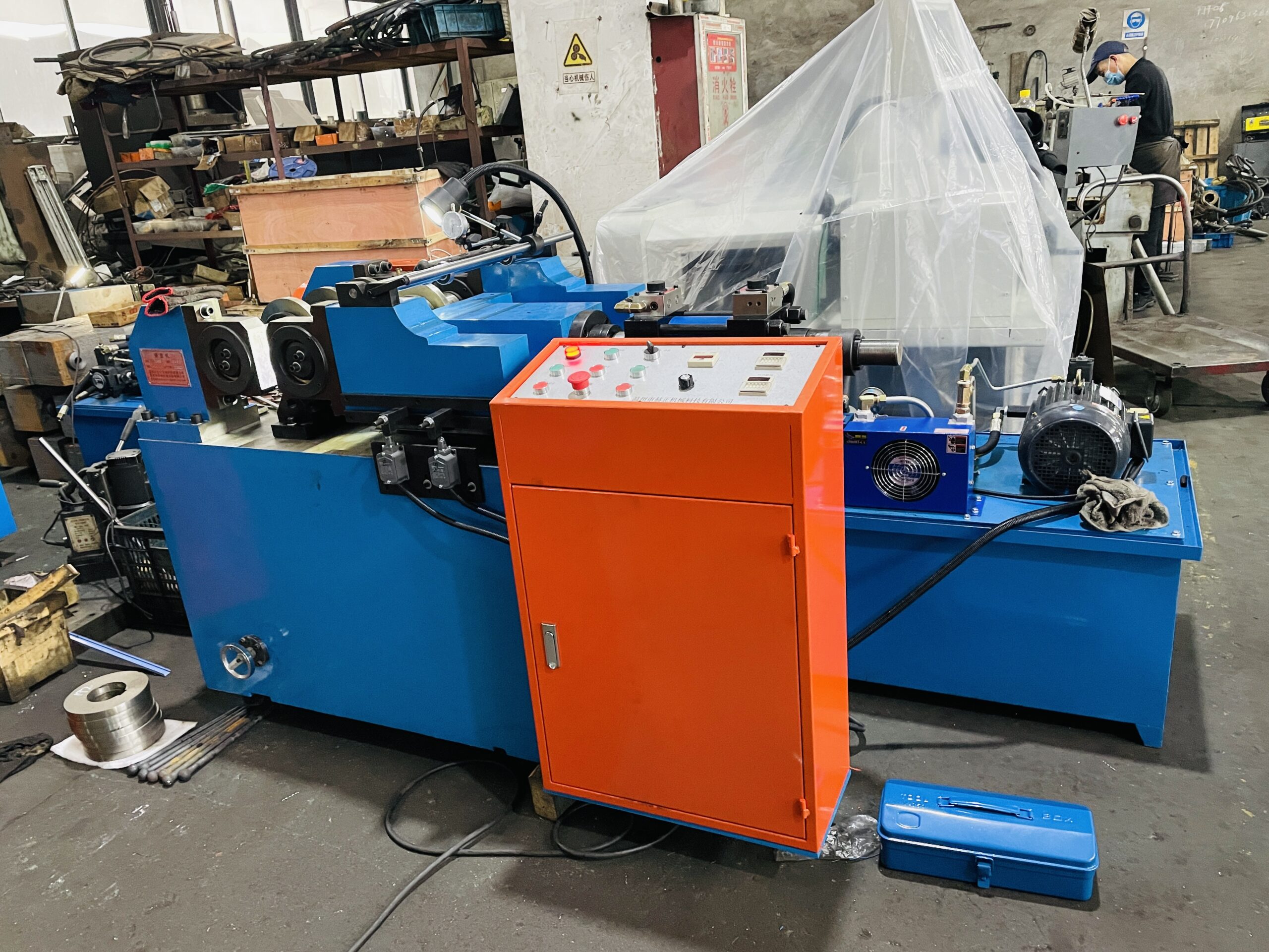
Projektikuva vahvistaa rullatyyppisen koneen, oppaat ja mittausalue. Se ei todista tiettyä rullan määrää, automaattinen suljetun silmukan ohjaus, nopeus tai tarkkuus.
Suositeltu telojen oikaisuprosessi
1. Tunnista hyväksytty versio ja vaihe
Käyttäjä valitsee reseptin tarkalle takomiselle, pituus, varren halkaisija, kovuus ja pinnan tila. Sekaosien tai väärän valmistusvaiheen pääsy rullasarjaan estetään.
2. Tarkista saapuva aihio
Halkeamat osat, taitoksia, vakava päävaurio, liiallinen mutka tai mitat validoidun ikkunan ulkopuolella erotetaan ennen oikaisua. Oikaisu ei ole taontavirheiden korjausmenetelmä.
3. Suuntaa ja ohjaa kuulapää
Sisääntuloohjain pitää nastan vakaana ja sallii hyväksytyn varsialueen pääsyn rulliin. Kuulapää ja siirtymä jäävät haitallisen linjakosketuksen ulkopuolelle. Jos osa sisältää asuntoja, niiden vaikutus kiertoon ja ruokintaan on validoitu.
4. Käytä hyväksyttyä telan asetusta
Rullaprofiili, risteyskulma, rako/paine, ohjaimen sijainti ja syöttönopeus ovat reseptiohjattuja. Asetuksen on saatava aikaan riittävä plastinen korjaus varteen ilman liiallista halkaisijan muutosta, kiillotus, sisennys, lämpötilan nousu tai jäännösstressiriski.

5. Mittaa käyttämällä sovittua peruspistettä
Osa mitataan määritellyistä asemista ja suunnasta. Piirustuksen mukaan, tämä voi olla koneen sisäinen tarkastus, ulkoinen mittari, optinen profiili tai kiertoon perustuva runout-testi. Kuvassa näkyvä indikaattorijärjestely tukee mittaustoimintaa, ei automaattinen lopputarkastusvaatimus.
6. Päätä passi, käsitellä uudelleen tai hylätä
Yksi ylimääräinen passi on sallittu vain, jos se sisältyy validoituun reseptiin. Rajoittamaton toistuva rullaus voi muuttaa pinnan kuntoa, halkaisija ja jäännösjännitys. Hyväksytyn ikkunan ulkopuolella olevat osat asetetaan karanteeniin teknistä tarkastusta varten.
7. Tarkista kunto ja geometria
Laatusuunnitelma voi sisältää pintatarkastuksen, mittatarkastuksia, magneettihiukkasten tai muiden halkeamien tarkastus, kovuuden tarkastus ja loppupään koneistus/kokoonpanokokeet. Tarkat menetelmät seuraavat materiaalia, valmistusvaihe ja asiakkaan piirustus.
Real Long Ball Studin suoristusvideo
Seuraava julkinen video liittyy alkuperäiseen pitkän kuulanastan artikkeliin ja näyttää projektin telojen oikaisulaitteet. Se tukee vain näkyvää prosessikonseptia. Se ei todista aiemmin sanottua 0.2 mm tulos, 20–45 HRC-alue, Intialainen asiakas, tuotannon lisäys tai asiakasarviointi.
Telan oikaisu tai mitatun pisteen korjaus?
| Päätöstekijä | Rullaoikaisu voi olla parempi, kun | Pistekorjaus voi olla parempi kun |
|---|---|---|
| Taivutuksen jakautuminen | Kaarevuus jakautuu tasaista vartta pitkin | Yksi tai useampi paikallinen huippupiste voidaan mitata |
| Yhteysalue | Jatkuva varren kosketus on sallittu | Vain valitut tuki- ja puristusalueet ovat sallittuja |
| Loppugeometria | Pää ja muut ominaisuudet voivat tyhjentää rulla-/ohjainjärjestelmän | Monimutkaiset päät tekevät jatkuvasta kulkemisesta vaarallisen |
| Pinta | Telan kosketus ja kaikki kiillotusvaikutukset ovat hyväksyttäviä | Valmiit pinnat vaativat paikallisia suojattuja työkaluja |
| Mittaus | Ennen/jälkeen tai näytetarkastus riittää | Suljetun silmukan mittaus tarvitaan jokaisen korjauksen jälkeen |
| Osa sekoitus | Vakaa, volyymiltaan suurempi perhe | Pienemmät tai korkean sekoituksen osat erityisillä resepteillä |
Kumpikaan menetelmä ei ole yleisesti "paras". Esimerkkitutkimus voi myös osoittaa, että oikaisu tulisi siirtää aikaisempaan valmistusvaiheeseen sen sijaan, että valmis kuulatappi pakotettaisiin jommankumman prosessin läpi..
Pää, Siirtymä ja pintasuojaus
| Riski | Ohjaus |
|---|---|
| Pallon pinnassa lommo tai naarmu | Poista pallo työrullista ja käytä hyväksyttyjä ohjaimia |
| Siirtymähalkeama | Sulje säde pois keskitetystä kuormituksesta; lisää vaadittu halkeamien tarkastus |
| Varren sisennys tai halkaisijan muutos | Sovita rullaprofiili, paine ja pinnan kunto; mittaa käsittelyn jälkeen |
| Litteä tai lanka tarttuu ohjaimeen | Määritä suunta/väli ja käytä versiokohtaisia työkaluja |
| Kovettunut kerrosvaurio | Vahvista kosketusjännitys ja korjausraja tuotantoa vastaavissa näytteissä |
| Ylikuumeneminen tai liiallinen kiillotus | Rajoita nopeutta/painetta/ajoja ja seuraa sovittua tilaa |
| Osa poistuu arvaamattomasti | Käytä positiivisia oppaita, vartiointi ja turvallinen keräys |
Näytetesti- ja hyväksymissuunnitelma
Edustavia näytteitä
- lyhin käytettävissä oleva rullan kosketuspituus ja suurin pään ja varren välinen suhde;
- varren vähimmäis- ja enimmäishalkaisijat;
- kaikki asiaankuuluvat taonta- ja lämpökäsittelyolosuhteet;
- jokainen asunto, kartiomainen, kierre- ja päätykokoonpano;
- osia todellisen sisääntulevan mutkan jakelussa;
- useita eriä, joissa taonta mittakaavassa, kovuus tai takajousto voi vaihdella.
Vaaditut todisteet
| Tallentaa | Hyväksymistodistus |
|---|---|
| Osan identiteetti | Piirustusversio, variantti, materiaalia, vaihe ja erä |
| Saapuva geometria | Ominaista, datum, asemat ja arvot |
| Resepti | Rullat, oppaita, rako/paine, kulma, nopeus- ja ohitusrajoitus |
| Lopullinen geometria | Sama määritelty ominaisuus plus asiakasmittarin korrelaatio |
| Mitat | Varren halkaisija ja toiminnalliset ominaisuudet pysyvät toleranssirajoissa |
| Pinta/siirtymä | Hyväksytty visuaalisen ja halkeaman tarkastuksen tulos |
| Tuotantokoe | Mitattu sykli, hillot, vaihto, tarkastus ja saatavuus |
Tutkimuksen tulee sisältää osia lähellä aiottua prosessirajaa, ei vain muutamia helppoja näytteitä.
Automation soveltamisala
| Taso | Tyypillinen laajuus |
|---|---|
| Manuaalinen | Kuljettaja kuormittaa, suorittaa hyväksytyn passin ja purkaa tarkastuksen |
| Avustettu | Syöttö/ulossyöttötuki ja ohjattu keräys |
| Automaattinen | Erottaminen, suuntaa, rullaa, mittaus ja tulosten lajittelu |
| jäljitettävissä | Osan/erän identiteetti, resepti, mittaus- ja prosessitiedot |
Automaattinen lataus riippuu siitä, takertuvatko kuulapäät, vaativatko tasaiset tai kartiomaiset suuntaukset ja onko pintakosketus sallittu. Automaatio ja jäljitettävyys ovat tilattuja laajuuksia, ei oletuksia konekuvasta.
Mikä ei ole yleinen lupaus
Ennen piirtämistä tarkistus ja näytteen validointi, tämä ratkaisu ei lupaa:
- 0.2 mm suoruus määrittelemättömälle ominaisuudelle;
- yksi prosessiikkuna jokaista 20–45 HRC-osaa kohden;
- soveltuu kootuille pallonivelille tai kokonaisille raidetangoille;
- turvallinen rullan kosketus valmiissa palloissa, kapenee, langat tai pinnoitteet;
- yksi rullaasetus kaikille pituuksille ja halkaisijoille;
- nolla halkeamia, merkkejä, halkaisijan muutos tai jäännösjännitysvaikutukset;
- kiinteä sykliaika, tuotannon lisääminen tai kustannusten vähentäminen;
- intialaisen asiakkaan tulos tai suosittelu ilman valtuutettuja tietueita.
Aiheeseen liittyvät sovellukset
Tarkista meidän Kiinnikkeiden ja työkalujen oikaisuratkaisut ja Ball Stud oikaisukone viereisiin sovelluksiin ja laitteisiin. Jos komponentissa on ohjaustanko tai koottu raidetankotoiminto, se vaatii erillisen datan ja toiminnallisen riskin tutkimuksen.
Tiedot lähetettäväksi ehdotusta varten
Most long ball stud straightening enquiries move faster when the buyer arrives with the koneen valintaopas akseleille, putket ja profiilit already worked through and a target range from the oikaisukoneiden hintaerittely.
Lähetä piirustus ja versio, edustavia näytteitä, pallon/varren/siirtymän mitat, litteät/kartio/kierteet, materiaalin ja lämpökäsittelyn reitti, tarkka valmistusvaihe, pinnan kunto, sisääntulevan mutkan jakelu, lopullinen ominaisuus ja perusarvo, asiakasmittari, kielletyt kosketusalueet, halkeamien tarkastusvaatimus, lähtökohde ja ensisijainen lataustapa.
Ota yhteyttä StraighteningTechiin näytepohjaiseen pitkän pallonastan oikaisututkimukseen. Määrittelemme sopivan prosessivaiheen, rulla tai pisteen korjauskonsepti, suojattuihin vyöhykkeisiin, mittausmenetelmä ja hyväksymistodistus varsinaiselle osaperheelle.
Usein kysytyt kysymykset
Onko kuulanasta sama kuin raidetanko?
Ei. Kuulatappi on pallonivelen sisällä oleva komponentti. Raidetanko on suurempi ohjausvivusto, joka sisältää tavallisesti pallonivelet ja säätöliittimen. Tämä ratkaisu koskee yksittäisiä pitkiä kuulatappiaihioita tai osia.
Voiko kuulapää kulkea suoristustelojen välissä?
Ei oletuksena. Pallo ja sen siirto ovat toimivia, erittäin kuormitetut vyöhykkeet. Työkalu normaalisti puhdistaa tai ohjaa ne samalla, kun hyväksytty yhtenäinen varsi menee teloihin. Kaikki suorat yhteydenotot edellyttävät nimenomaista piirustuksen hyväksyntää ja näytteen validointia.
Voiko osia karkaistua 45 HRC on suoristettu telalla?
Mahdollisesti tietylle materiaalille, kovuusprofiili, geometria ja sisääntuleva mutka, mutta pelkkä määrä ei riitä. Springback, kotelon syvyys, siirtymästressiä, halkeamisriski ja sallittu pintakosketus on testattava.
Is 0.2 mm suoruus- tai juoksuvaatimus?
Pelkkä luku ei voi vastata tähän. Piirustuksessa on nimettävä ominaisuus, kontrolloitu pituus, datum, mittauspaikat ja arviointimenetelmä. Kone ja asiakasmittari tarvitsevat sitten korrelaatiotutkimuksen.
Milloin pisteen korjausta tulisi harkita sen sijaan?
Kun mutka on paikallinen, käyttökelpoinen rullan kosketuspituus on lyhyt, monimutkaiset ominaisuudet estävät turvallisen jatkuvan kulun tai viimeistellyt pinnat vaativat valikoivaa työkalua ja suljetun silmukan mittausta.
Tekninen viiteraja
- ZF pallonivelet: https://press.zf.com/press/en/media/media_2252.html
- ZF Raidetangot: https://www.zf.com/products/en/cars/products_65853.html
- ZF Ohjaus ja alustan osat: https://aftermarket.zf.com/sg/aftermarket-portal/our-portfolio/passenger-cars/products/steering-and-chassis-parts/
- MOOG Pallonivelet: https://www.moogparts.com/en-eu/products/suspension/ball-joints.html
- Danielin oikaisukoneet: https://www.danieli.com/en/products/products-processes-and-technologies/ingot-casting_26_12.htm
- Mair Researchin kaksirullainen oikaisukone: https://www.mair-research.com/en/two-roll-straightening-machine/
- MAE-työkappaleet ja sovellukset: https://mae-group.com/fi/workpieces-applications/
Nämä viittaukset tukevat pallonivelterminologiaa, materiaalin kunnon monimuotoisuus ja yleiset telan/paineoikaisun periaatteet. Ne eivät todista, että toisen toimittajan suorituskyky koskee StraighteningTech-kokoonpanoa.