
Οι πολλαπλές ψύξης υγρού κατανέμουν το ψυκτικό μέσω της μπαταρίας, κέντρο δεδομένων, ηλεκτρονικά ή βιομηχανικά συστήματα διαχείρισης θερμότητας. Το μακρύ κοίλο προφίλ τους, οι συγκολλημένες θύρες και οι διεπαφές στεγανοποίησης πρέπει να παραμένουν γεωμετρικά σταθερές, έτσι ώστε το συγκρότημα να ταιριάζει στο σύστημα ψύξης χωρίς πίεση, κίνδυνος διαρροής ή προβλήματα ευθυγράμμισης.
Αυτή η προτεινόμενη λύση βασίζεται σε μια ορθογώνια κοίλη πολλαπλή από ανοξείδωτο χάλυβα 304 λίτρων, με μέτρηση περίπου 78 mm πλάτος, 45 mm ύψος και 1800 mm μήκος, με α 3 τοίχος mm. Ο πελάτης αναφέρει δύο διαφορετικά στάδια παραμόρφωσης: τα εισερχόμενα άκρα του σωλήνα μπορεί να είναι στριμμένα κατά περίπου 20 mm, και η συγκόλληση εισάγει μια δεύτερη παραμόρφωση κάμψης. Αυτά είναι διαφορετικά ελαττώματα και θα πρέπει να αντιμετωπίζονται με ξεχωριστές στρατηγικές ευθυγράμμισης και όχι με έναν γενικό κύκλο πρέσας.

Τεμάχιο εργασίας και Απαίτηση πελάτη
Η πολλαπλή αρχίζει ως ένας μακρύς ορθογώνιος κοίλος σωλήνας και αργότερα δέχεται πολλαπλούς κλάδους, θυρίδες ή συγκολλημένα εξαρτήματα. Ο πελάτης επί του παρόντος διορθώνει την αρχική περιστροφή χειροκίνητα, αναλαμβάνοντας περίπου 30 λεπτά ανά μέρος. Μετά από διόρθωση περιστροφής, το τμήμα είναι συγκολλημένο και μπορεί να λυγίσει ξανά, δημιουργώντας μια άλλη απαίτηση ευθυγράμμισης πριν από την τελική συναρμολόγηση ή τη δοκιμή διαρροής.
Ο αναφερόμενος όγκος παραγωγής είναι 12,000 ανταλλακτικά ανά μήνα και η ζητούμενη ακρίβεια μετά το ίσιωμα είναι 0.15 mm. Πριν αυτή η τιμή γίνει εγγύηση εξοπλισμού, το σχέδιο πρέπει να διευκρινίζει εάν ελέγχει την ευθύτητα, ομαλότητα, προφίλ, τελική θέση, θέση θύρας ή άλλο γεωμετρικό χαρακτηριστικό, και σε ποιο μήκος αναφοράς μετράται.
| Στοιχείο έργου | Εισαγωγή πελατών / Κατάσταση |
|---|---|
| τεμάχιο εργασίας | Συλλέκτης υγρής ψύξης / πολλαπλή διανομής |
| Υλικό | 304L από ανοξείδωτο χάλυβα |
| Τμήμα | Ορθογώνιο κοίλο προφίλ, περίπου 78 × 45 mm |
| Πάχος Τοίχου | 3 mm |
| Μήκος | Περίπου 1800 mm |
| Αρχικό ελάττωμα | Η συστροφή στο άκρο του σωλήνα αναφέρθηκε περίπου 20 mm |
| Δεύτερο ελάττωμα | Κάμψη μετά τη συγκόλληση |
| Τρέχουσα μέθοδος | Χειροκίνητη διόρθωση περιστροφής, περίπου 30 min/τμήμα |
| Όγκος Παραγωγής | 12,000 μέρη/μήνα |
| Ζητούμενη ακρίβεια | 0.15 mm; χαρακτηριστικό και δεδομένο που πρέπει να επιβεβαιωθεί |
| Προτεινόμενη Λύση | Εξοπλισμός διόρθωσης περιστροφής συν ένα μηχάνημα ισιώματος κάμψης |
Η συστροφή και η κάμψη πρέπει να μετρώνται χωριστά
Περιστροφή σημαίνει ότι μια διατομή έχει περιστραφεί σε σχέση με την άλλη κατά μήκος του προφίλ. Κάμψη σημαίνει ότι η διαμήκης κεντρική γραμμή ή η επιφάνεια αναφοράς αποκλίνει από την απαιτούμενη γραμμή. Μια πολλαπλή μπορεί να είναι ευθεία στην πλάγια όψη αλλά να έχει ακόμα περιστρεφόμενα άκρα, ή μπορεί να έχει σωστό προσανατολισμό στο άκρο κατά την υπόκλιση μετά τη συγκόλληση.
Η χρήση μόνο ενός καθετήρα κατακόρυφης μετατόπισης δεν μπορεί να περιγράψει πλήρως το σφάλμα στρέψης. Ο σταθμός συστροφής χρειάζεται γωνιακή ή μέτρηση πολλαπλών επιφανειών του ορθογώνιου προφίλ ή των τελικών δεδομένων. Ο σταθμός ευθυγράμμισης κάμψης χρειάζεται γραμμικές μετρήσεις κατά μήκος των συμφωνημένων επιφανειών αναφοράς ή κεντρικής γραμμής. Η θέση της θύρας και της φλάντζας μπορεί να απαιτεί πρόσθετους μετρητές εάν είναι λειτουργικά χαρακτηριστικά αποδοχής.
| Ελάττωμα | Τυπική μέτρηση | Απαιτούμενη διόρθωση |
|---|---|---|
| Τελική συστροφή / συστροφή | Γωνιακή σύγκριση ακραίων διατομών, ανιχνευτές πολλαπλών επιφανειών, λέιζερ ή μετρητή στερέωσης | Ελεγχόμενη αντίστροφη ροπή ή ίσιωμα στρέψης |
| Κάθετο τόξο | Μέτρηση μετατόπισης κατά μήκος του άνω/κάτω σημείου | Διόρθωση κάθετης πίεσης |
| Οριζόντιο τόξο | Πλευρική μέτρηση κατά μήκος της όψης αναφοράς ή της κεντρικής γραμμής | Οριζόντια διόρθωση ή επαναπροσανατολισμός |
| Τοπική παραμόρφωση συγκόλλησης | Μέτρηση κοντά σε συγκολλημένες θύρες ή ζώνες που επηρεάζονται από τη θερμότητα | Τοπική διόρθωση σημείων με όρια τάσεων |
| Λιμάνι / κακή ευθυγράμμιση προσαρμογής | Αναπόσπαστο εξάρτημα, όραμα, CMM ή αποκλειστικό λειτουργικό μετρητή | Διαχωρίστε την αποδοχή ή την τοπική διόρθωση εάν επικυρωθεί |
ο 0.15 Η απαίτηση mm δεν μπορεί να αποδοθεί σε όλα αυτά τα χαρακτηριστικά χωρίς να αντληθούν στοιχεία. Κάθε ελεγχόμενο χαρακτηριστικό θα πρέπει να έχει το δικό του δεδομένο, θέση μέτρησης και κανόνας ΟΚ/ΝΟΚ.
Γιατί οι πολλαπλές ψύξης υγρού είναι δύσκολο να ισιώσουν
ο 3 Το κοίλο τοίχωμα mm δημιουργεί κίνδυνο σύνθλιψης, εσοχή ή τοπικός λυγισμός κάτω από συγκεντρωμένη στήριξη ή επαφή με πίεση. Η ορθογώνια διατομή έχει διαφορετική ακαμψία ως προς τον κύριο και τον δευτερεύοντα άξονά της, Έτσι, η ίδια διαδρομή πίεσης παράγει διαφορετικές αποκρίσεις ανάλογα με τον προσανατολισμό. The section-preservation logic for smaller hollow parts is covered in ίσιωμα σωλήνα λεπτού τοιχώματος.
Οι συγκολλήσεις κάνουν την απόκριση ακόμη λιγότερο ομοιόμορφη. Η είσοδος θερμότητας και η ακολουθία συγκόλλησης μπορούν να τραβήξουν την πολλαπλή προς τη συγκολλημένη πλευρά, ενώ οι πολλές θύρες δημιουργούν τοπικές αλλαγές ακαμψίας. Πατώντας σε μια θύρα, σφαιρίδιο συγκόλλησης, Η επιφάνεια στεγανοποίησης ή το λεπτό τοίχωμα που δεν υποστηρίζεται μπορεί να βλάψει ένα λειτουργικό χαρακτηριστικό. Επομένως, η διαδικασία πρέπει να χρησιμοποιεί διαμορφωμένο στήριγμα και εργαλεία πρέσας τοποθετημένα μεταξύ ή γύρω από κρίσιμα χαρακτηριστικά.
| Πρόκληση | Κίνδυνος | Μηχανικός Έλεγχος |
|---|---|---|
| 1800 προφίλ μήκους mm | Αυτο-βάρος και ασταθής μέτρηση | Κατανεμημένα στηρίγματα και μέτρηση πλήρους μήκους βάσει δεδομένων |
| 3 χιλ. κοίλος τοίχος | Σύνθλιψη ή μόνιμη εσοχή | Εργαλεία με ευρύ περίγραμμα, εσωτερική υποστήριξη όπου χρειάζεται, όρια δύναμης/εγκεφαλικού επεισοδίου |
| Ορθογώνιο τμήμα | Διαφορετική ακαμψία ανά κατεύθυνση | Ξεχωριστή κάθετη, οριζόντιες και στρεπτικές συνταγές |
| Σχετικά με 20 mm συστροφή άκρου | Δεν μπορεί να αφαιρεθεί αξιόπιστα με απλό κάθετο πάτημα | Ειδικός σταθμός στρέψης και γωνιακή ανάδραση |
| Πολλαπλές συγκολλημένες θύρες | Η τοπική ακαμψία και η θερμική παραμόρφωση ποικίλλουν κατά μήκος | Ζώνες πρέσας για συγκεκριμένο μοντέλο και τοπική μέτρηση |
| 12,000 μέρη/μήνα | Η μη αυτόματη διαδικασία 30 λεπτών δεν μπορεί να υποστηρίξει την απαιτούμενη έξοδο | Αυτοματοποιημένος χειρισμός, παράλληλες λειτουργίες και επικύρωση χρόνου takt |
Συνιστώμενη ιδέα ισιώματος δύο σταδίων
Η προτιμώμενη ιδέα διαχωρίζει τη διόρθωση συστροφής πριν από τη συγκόλληση από τη διόρθωση κάμψης μετά τη συγκόλληση. Ο πρώτος σταθμός δέχεται τον ορθογώνιο σωλήνα ή προσυναρμολόγηση, εντοπίζει και τα δύο άκρα και μετρά το σχετικό γωνιακό σφάλμα. Ένας ελεγχόμενος περιστροφικός ενεργοποιητής ή αντίθετοι σφιγκτήρες εφαρμόζουν αντίστροφη ροπή σε επικυρωμένα βήματα, ακολουθούμενη από επαναμέτρηση.
Μετά τη συγκόλληση, η πολλαπλή εισέρχεται σε σταθμό ευθυγράμμισης σημείου μακράς κλίνης. Πολλαπλές υποστηρίξεις καθορίζουν το δεδομένο, οι αισθητήρες χαρτογραφούν την καμπή κατά μήκος, και ένα κινητό ή ευρετηριασμένο πιεστήριο εφαρμόζει ελεγχόμενη διόρθωση σε εγκεκριμένες θέσεις. Το βίντεο του έργου δείχνει αυτή την πολύπλευρη ιδέα ισιώματος της πρέσας; δεν δείχνει ούτε αποδεικνύει τον ξεχωριστό σταθμό διόρθωσης στρέψης προ-συγκόλλησης.
Στάδιο 1: Διόρθωση συστροφής πριν από τη συγκόλληση
Βήμα 1: Προσδιορίστε το προφίλ και δημιουργήστε δεδομένα τέλους
Το εξάρτημα εντοπίζει τον ορθογώνιο σωλήνα χρησιμοποιώντας συμφωνημένες όψεις αναφοράς ή ακραία χαρακτηριστικά. Οι σφιγκτήρες πρέπει να κατανέμουν την επαφή κατά μήκος του 3 χιλ. τοίχου χωρίς να δημιουργεί βαθουλώματα. Εάν το εξάρτημα περιέχει ήδη ευαίσθητα εξαρτήματα, αυτές οι περιοχές παραμένουν εκτός των ζωνών σφιγκτήρα.
Βήμα 2: Μετρήστε την αρχική στρέψη
Το σύστημα συγκρίνει τον γωνιακό προσανατολισμό και των δύο άκρων ή πολλών διατομών. Η αναφερόμενη «στρέψη 20 mm» θα πρέπει να μετατραπεί σε μια καθορισμένη γεωμετρική μέτρηση—όπως μετατόπιση τελικής γωνίας σε γνωστή ακτίνα μετρητή ή γωνιακές μοίρες— έτσι ώστε το σύστημα ελέγχου και η επιθεώρηση πελάτη να χρησιμοποιούν τον ίδιο ορισμό.
Βήμα 3: Εφαρμόστε ελεγχόμενη αντίστροφη ροπή
Το ένα άκρο συγκρατείται ενώ το άλλο περιστρέφεται προς την αντίθετη κατεύθυνση χρησιμοποιώντας ελεγχόμενη ροπή ή γωνιακή μετατόπιση. Επειδή το ανοξείδωτο ατσάλι 304L αναπηδά πίσω, ο σταθμός χρειάζεται μια επικυρωμένη στρατηγική over-twist. Μέγιστη ροπή, οι κύκλοι γωνίας και διόρθωσης προστατεύουν το κοίλο τμήμα και τυχόν συγκολλημένες ραφές.
Βήμα 4: Επαναμετρήστε και αποδεχτείτε το τμήμα προ-συγκόλλησης
Το εξάρτημα μετράται ξανά μετά από κάθε διόρθωση. Μόνο προφίλ εντός του συμφωνημένου ορίου στρέψης προ-συγκόλλησης προχωρούν σε συγκόλληση. Η καταγραφή της εισερχόμενης και της διορθωμένης περιστροφής μπορεί επίσης να αποκαλύψει προβλήματα στην παροχή σωλήνα, αποθήκευση ή ανάντη διαμόρφωση.
Στάδιο 2: Ίσιωμα μετά την κάμψη της συγκόλλησης
Βήμα 1: Φορτώστε και υποστηρίξτε τη συγκολλημένη πολλαπλή
Η έτοιμη ή ημικατεργασμένη πολλαπλή τοποθετείται σε κατανεμημένα ρυθμιζόμενα στηρίγματα. Το εξάρτημα πρέπει να αντιπροσωπεύει το μακρύ σώμα, πολλαπλές θύρες και διαφορετικές τελικές δομές, ενώ αφήνουν καθαρή πρόσβαση για τους αισθητήρες και την κεφαλή πρέσας.
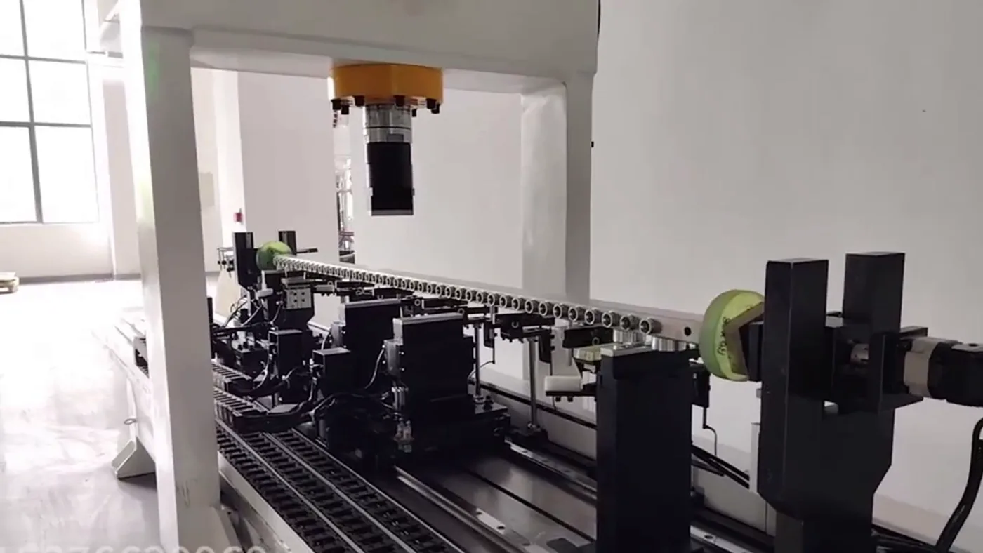
Τα σημεία στήριξης πρέπει να έρχονται σε επαφή με εγκεκριμένες ευρείες επιφάνειες. λιμάνια, σφαιρίδια συγκόλλησης, Ως προστατευόμενες ζώνες ορίζονται οι όψεις στεγανοποίησης και τα λεπτά μη υποστηρίγματα τοιχώματα. Contact-zone validation follows the same εργαλεία προστασίας επιφανειών rules.
Βήμα 2: Χαρτογραφήστε την παραμόρφωση που προκαλείται από συγκόλληση
Ανιχνευτές επαφής, αισθητήρες λέιζερ ή ένας συνδυασμός μετρούν τη σχετική επιφάνεια αναφοράς σε πολλαπλές θέσεις. Ο ελεγκτής διακρίνει τη συνολική πλώρη από την τοπική παραμόρφωση κοντά σε συγκολλήσεις. Εάν ελέγχονται τόσο η κάθετη όσο και η οριζόντια κάμψη, το σύστημα χρειάζεται μετρήσεις και προς τις δύο κατευθύνσεις ή μια επικυρωμένη ακολουθία μερικού επαναπροσανατολισμού.
Βήμα 3: Υπολογισμός θέσεων τύπου και υποστήριξης
Το χειριστήριο προσδιορίζει την κορυφή κάμψης και επιλέγει ένα ασφαλές σημείο διόρθωσης μεταξύ των κρίσιμων θυρών. Η τοπική ακαμψία του τμήματος, Η απόσταση από την πλησιέστερη συγκόλληση και το άνοιγμα στήριξης επηρεάζουν την αρχική διαδρομή. Η στρατηγική πρέπει να αποφεύγει απλώς το πάτημα στη μεγαλύτερη μετρούμενη απόκλιση όταν αυτή η τοποθεσία είναι μια αδύναμη ή λειτουργική περιοχή.
Βήμα 4: Εφαρμογή Ελεγχόμενης Διόρθωσης Τύπου
Η πρέσα εφαρμόζει μια περιορισμένη διαδρομή υπερβολικής κάμψης για να αντισταθμίσει την επιστροφή του ελατηρίου. Τα εργαλεία με ευρύ περίγραμμα κατανέμουν το φορτίο στον ορθογώνιο σωλήνα. Όπου ο κίνδυνος κατάρρευσης του τοίχου είναι υψηλός, εσωτερικά μανδρέλια, Μπορεί να απαιτηθούν τοπικά υλικά πλήρωσης ή εξειδικευμένη εξωτερική υποστήριξη μετά από έλεγχο μηχανικής.

Τα όρια δύναμης και μετατόπισης πρέπει να αναπτύσσονται από αντιπροσωπευτικά συγκολλημένα δείγματα. Μια ξαφνική αλλαγή στην απόκριση δύναμης-μετατόπισης μπορεί να υποδηλώνει λανθασμένη στήριξη, διαφορετικό μοντέλο ανταλλακτικού ή τοπική κατάρρευση και θα πρέπει να ενεργοποιήσει συναγερμό.
Βήμα 5: Επαναμέτρηση κλειστού βρόχου
Μετά από διόρθωση, η πολλαπλότητα μετριέται στο ίδιο σημείο αναφοράς. Πρόσθετη διόρθωση επιτρέπεται μόνο εντός των επικυρωμένων ορίων κύκλου και διαδρομής. Εάν ένα εξάρτημα δεν μπορεί να φτάσει στο στόχο χωρίς να διακινδυνεύσει το λιμάνι, ζημιά συγκόλλησης ή τοίχου, αποστέλλεται σε NOK ή χειροκίνητη αναθεώρηση μηχανικής.
Βήμα 6: Τελική Επιθεώρηση και Μεταφορά
Η τελική αποδοχή μπορεί να περιλαμβάνει ευθύτητα/επιπεδότητα, τελικός προσανατολισμός, θέση λιμένα, κατάσταση επιφάνειας και δοκιμή διαρροής. Ο ισιωτής δεν θα πρέπει να ισχυρίζεται ότι επαληθεύει την ακεραιότητα της διαρροής εκτός εάν στην πραγματικότητα περιλαμβάνεται ένας ενσωματωμένος σταθμός δοκιμής διαρροής.
Έλεγχος χωρητικότητας για 12,000 Μέρη ανά μήνα
Ο όγκος παραγωγής πρέπει να μετατραπεί σε χρόνο takt χρησιμοποιώντας τις πραγματικές εργάσιμες ημέρες, βάρδιες, διαθέσιμες ώρες και στοχευμένη χρήση εξοπλισμού. Για παράδειγμα, 12,000 Τα ανταλλακτικά ανά μήνα δεν μπορούν από μόνα τους να καθορίσουν τον απαιτούμενο κύκλο έως ότου γίνει γνωστός ο αριθμός των ωρών παραγωγής και εάν χρειάζονται και τα δύο στάδια διόρθωσης για κάθε εξάρτημα.
Η τρέχουσα χειροκίνητη διόρθωση περιστροφής περίπου 30 Τα λεπτά ανά μέρος παρέχουν μια βασική γραμμή, δεν είναι αυτόματο-μηχανικό αποτέλεσμα. Ένα πλήρες μοντέλο χωρητικότητας θα πρέπει να περιλαμβάνει φόρτωση, μέτρηση, διόρθωση, επαναμέτρηση, εκφόρτωση, μετάβαση, επιθεώρηση εργαλείου, προγραμματισμένο χρόνο διακοπής λειτουργίας και το ποσοστό των εξαρτημάτων που χρειάζονται πρόσθετους κύκλους.
| Είσοδος χωρητικότητας | Απαιτούμενη τιμή |
|---|---|
| Μηνιαία ποσότητα | 12,000 εξαρτήματα |
| Εργάσιμες ημέρες/μήνα | Πελάτης για επιβεβαίωση |
| Βάρδιες/ημέρα και ώρες/βάρδια | Πελάτης για επιβεβαίωση |
| Στόχος ΟΕΕ / χρησιμοποίηση | Πελάτης για επιβεβαίωση |
| Ποσοστό που απαιτεί διόρθωση συστροφής πριν από τη συγκόλληση | Να μετρηθεί |
| Ποσοστό που απαιτεί διόρθωση κάμψης μετά τη συγκόλληση | Να μετρηθεί |
| Μέσος / μέγιστους κύκλους διόρθωσης | Απαιτείται αποτέλεσμα δείγματος δοκιμής |
| Απαιτούμενος ρυθμιστής μεταξύ συγκόλλησης και ευθυγράμμισης | Απόφαση διάταξης γραμμής |
Προτεινόμενη διαμόρφωση κελιού
| Μονάδα μέτρησης | Προτεινόμενη διαμόρφωση |
|---|---|
| Σταθμός Προσυγκόλλησης | Σύσφιξη προφίλ, μέτρηση γωνίας/στρέψης και ελεγχόμενη αντίστροφη περιστροφή |
| Σταθμός Μετασυγκόλλησης | Ισιωτικό πρέσας με μακρύ κρεβάτι με ρυθμιζόμενα κατανεμημένα στηρίγματα |
| Σύστημα Μετρήσεων | Μέτρηση γωνιακής/τελικής βάσης συν ανίχνευση γραμμικής μετατόπισης πολλαπλών σημείων |
| Εργαλεία | Ευρύ περιγράμματος επαφή για 78 × 45 × 3 χιλ. κοίλο τμήμα |
| Πιεστικός | Κινητή ή ευρετηριασμένη κεφαλή πρέσας με όρια δύναμης/μετατόπισης |
| Χειριζόμενος | Χειροκίνητη βοήθεια, σκελετό ή ρομπότ ανάλογα με το μερικό βάρος και τακτ |
| Έλεγχοι | Ξεχωριστές συνταγές πριν και μετά τη συγκόλληση, διόρθωση κλειστού βρόχου και λογική ΟΚ/ΝΟΚ |
| Δεδομένα | Εισερχόμενη/τελική στροφή και κάμψη, μέτρηση διόρθωσης, συνταγή και αναγνωριστικό ανταλλακτικού όπως απαιτείται |
| Ασφάλεια | Συμπλεκόμενη φύλαξη, στρατηγική προστασίας από υπερφόρτωση και ανίχνευσης ανώμαλης κατάρρευσης |
Σχέδιο Επικύρωσης Έργου
Τα αντιπροσωπευτικά δείγματα πρέπει να περιλαμβάνουν την κανονική και τη μέγιστη εισερχόμενη συστροφή, διαφορετικές παρτίδες συγκόλλησης και τη μεγαλύτερη αναμενόμενη παραμόρφωση μετά τη συγκόλληση. Η δοκιμή πρέπει να επαληθεύει εάν το 3 Το προφίλ mm μπορεί να διορθωθεί χωρίς εσοχές, ζημιά στο λιμάνι, ρωγμές συγκόλλησης ή απαράδεκτη υπολειμματική τάση.
Η αναφορά αποδοχής θα πρέπει να επισημαίνει με σαφήνεια τις απαιτήσεις των πελατών, αποτελέσματα δειγματοληπτικών δοκιμών και αργότερα αποτελέσματα παραγωγής. Θα πρέπει επίσης να ορίσει εάν 0.15 mm είναι εφικτό και έχει νόημα για το πλήρες 1800 πολλαπλή mm, ένα τοπικό εύρος δεδομένων, μια επιφάνεια σφράγισης, θέση θύρας ή άλλο χαρακτηριστικό σχεδίασης.
Πληροφορίες που απαιτούνται για μια πρόταση πολλαπλής υγρής ψύξης
Δώστε το πλήρες σχέδιο και το GD&Τ, 3μοντέλο D, πιστοποιητικό υλικού, αλληλουχία συγκόλλησης, μερικό βάρος, ορισμός και διανομή εισερχόμενης συστροφής, χάρτης παραμόρφωσης μετά τη συγκόλληση, τελική ανοχή και δεδομένο, προστατευμένες επιφάνειες, επιτρεπόμενες ζώνες σφιγκτήρα/στήριξης/πίεσης, απαιτούμενα κριτήρια διαρροής και επιφάνειας, ημερολόγιο εργασίας, στόχος, διάταξη γραμμής και αντιπροσωπευτικά δείγματα πριν και μετά τη συγκόλληση.
Αυτές οι είσοδοι καθορίζουν εάν το έργο χρειάζεται δύο ανεξάρτητα μηχανήματα, ένα συνδυασμένο κύτταρο, πολλαπλούς άξονες διόρθωσης, εσωτερικό στήριγμα σωλήνα, αυτοματοποιημένο χειρισμό ή μετρητή κατάντη.
FAQ
Μπορεί ένα μηχάνημα να διορθώσει τόσο τη συστροφή όσο και την κάμψη?
Είναι δυνατή η ενσωμάτωση πολλών αξόνων σε ένα προσαρμοσμένο κελί, αλλά η συστροφή και η κάμψη απαιτούν διαφορετικές μετρήσεις και ενέργειες διόρθωσης. Οι ξεχωριστοί σταθμοί είναι συχνά πιο σαφείς και πιο εύκολο να επικυρωθούν για μια γραμμή μεγάλου όγκου.
Γιατί δεν αρκεί ένα απλό κάθετο πάτημα για το αναφερόμενο 20 συστροφή χιλ?
Το κάθετο πάτημα διορθώνει κυρίως την κάμψη. Η στρέψη απαιτεί ελεγχόμενη σχετική περιστροφή των άκρων του προφίλ ή άλλο επικυρωμένο μηχανισμό συστροφής με γωνιακή ανάδραση.
Πώς είναι το 3 mm με προστασία τοίχου από ανοξείδωτο χάλυβα?
Το εξάρτημα και η πρέσα χρησιμοποιούν ευρεία επαφή με το περίγραμμα σε εγκεκριμένες επιφάνειες, με συντηρητικά όρια δύναμης/κτυπήματος. Μπορεί να απαιτείται εσωτερική υποστήριξη όπου ο κίνδυνος τοπικής κατάρρευσης είναι υψηλός.
Μπορεί η γραμμή να πετύχει 0.15 ακρίβεια mm?
Η τιμή χρειάζεται πρώτα ορισμό σχεδίου και δεδομένο. Η δυνατότητα επίτευξης εξαρτάται από την πλήρη γεωμετρία, κατανομή συγκόλλησης, υλική ανταπόκριση, μέθοδος μέτρησης και αποτελέσματα δειγματοληψίας.
Μπορεί να χειριστεί αυτή η διαδικασία 12,000 πολλαπλές ανά μήνα?
Ο μηνιαίος όγκος πρέπει να μετατραπεί σε χρόνο takt χρησιμοποιώντας εργάσιμες ημέρες, βάρδιες, ΟΕΕ και το ποσοστό των εξαρτημάτων που απαιτούν κάθε στάδιο διόρθωσης. Η χωρητικότητα επιβεβαιώνεται μόνο αφού υπάρχουν διαθέσιμα δεδομένα κύκλου δειγμάτων.
Το βίντεο δείχνει την πλήρη λύση σε δύο στάδια;?
Οχι. Δείχνει τον σταθμό ισιώματος με μεγάλη πολλαπλή πίεση. Ο ξεχωριστός εξοπλισμός διόρθωσης συστροφής πριν από τη συγκόλληση που περιγράφεται στην προτεινόμενη λύση δεν αποδεικνύεται από αυτό το βίντεο.
Σύναψη
Οι πολλαπλές ψύξης υγρού απαιτούν περισσότερα από μια γενική πρέσα ισιώματος. Ο εισερχόμενος ορθογώνιος σωλήνας μπορεί να έχει σφάλμα στρέψης, η συγκόλληση δημιουργεί μια δεύτερη παραμόρφωση κάμψης, και το λεπτό κοίλο τμήμα 304L πρέπει να διορθωθεί χωρίς θυρίδες σύνθλιψης, συγκολλήσεις ή διεπαφές στεγανοποίησης.
To turn this liquid-cooling manifold guidance into a purchase decision, ξεκινήστε με το αναλυτική περιγραφή επιλογής ισιωτικών και τεστ πίεσης των αριθμών με το εικόνα προϋπολογισμού για ισιωτική μηχανή.
Στείλτε το σχέδιο πολλαπλής, ορισμός συστροφής, αλληλουχία συγκόλλησης, δεδομένα παραμόρφωσης μετά τη συγκόλληση, δεδομένο στόχου, μηνιαίο ημερολόγιο παραγωγής και αντιπροσωπευτικά δείγματα. Μπορούμε στη συνέχεια να σχεδιάσουμε και να κατασκευάσουμε μια επικυρωμένη λύση ισιώματος συστροφής και μετά τη συγκόλληση κάμψης γύρω από το πραγματικό τεμάχιο εργασίας και την απαίτηση takt.