
Mehrere Verschiebungsmessungen können eine Langwellenprüfung von einem einzelnen Peak in eine Fehlerkarte umwandeln. Dieser Wert hängt nicht nur vom Sensor ab: Stützgeometrie, Bezugssitz, Sondenkontakt, Drehung/Indizierung, Synchronisation, Umgebungsbedingungen und die Berechnungsregel beeinflussen alle, was gemeldet wird.

*Illustration des technischen Konzepts. Es handelt sich nicht um eine Sensorspezifikation, installiertes System oder verifiziertes Messergebnis.*
Definieren Sie die Charakteristik, bevor Sie Sensoren auswählen
Geben Sie zunächst an, ob das Akzeptanzmerkmal die Geradheit der Mittellinie ist, lokaler Bogen, Rundlauf relativ zu einem Bezugspunkt, Profilabweichung oder ein anderes kontrolliertes Ergebnis. Eine Sensorspannungs- oder Verschiebungsspur ist nicht selbst die Anforderung des Kunden. Der Prüfplan muss Bezugsmerkmale identifizieren, unterstützt, Stationen, Orientierungen, Spanne, Berechnung, Einheiten, Grenzen und den Zustand, in dem das Teil angenommen wird.
| Element | Frage zum Schließen |
|---|---|
| Datum | Welche Merkmale legen die Referenzachse oder -fläche fest?? |
| Unterstützung | Reproduziert es den Zustand des Kunden oder des freigegebenen Teils?? |
| Sondenpfad | Kontaktstellen sind funktionsfähig und vor Beschädigungen geschützt? |
| Stationen | Erfassen sie bekannte Biegezonen und Merkmalsübergänge?? |
| Drehung/Indizierung | Wie bleibt die Orientierung zwischen den Lesungen erhalten?? |
| Berechnung | Wie werden Messwerte in die Regelkennlinie umgerechnet?? |
Für Datumskontrollen, sehen Reinigung des Wellenmittellochs und Vorbereitung des Bezugspunkts Und Wiederholgenauigkeit der Vorrichtung und Bezugspunkteinstellung.
How an LVDT Works, and Why Its Physics Matters
The linear variable differential transformer earns its place on production machinery through a short list of physical virtues. Inside the housing, a primary coil is excited with an alternating current, and two secondary coils sit either side of it; a ferromagnetic core, attached to the probe tip by a slim push rod, slides along the axis. With the core centered, the induced voltages in the two secondaries balance; displace the core and the balance tips in proportion to the movement. The electronics read the amplitude and phase of that imbalance and report displacement. Because the core never touches the coils, there is no friction or wear inside the sensor; because the coupling is inductive, the reading is largely indifferent to dust, oil mist and humidity that blind optical sensors; and because the moving mass is small, the tip can follow moderate surface motion faithfully. The trade-offs are equally physical: it needs signal conditioning and calibration against a reference, the raw output is relative rather than absolute, and the probe tip itself is a mechanical component with its own condition, force and wear story.
Where Errors Enter Between Probe and Number
Treating the chain as one system, as the section above demands, means knowing the specific doors through which error walks in. Thermal drift: the sensor body, the fixture and the part all expand and contract with temperature, and on a machine that warms through a shift, a morning zero and an afternoon reading are not the same event — hence reference checks on a master at intervals the procedure defines. Mounting: a probe on a long, unsupported bracket is a cantilever with its own compliance, and vibration or cable pull moves the whole assembly relative to the part, indistinguishable from part movement in the data. Dynamics: when the part or probe moves during scanning, the stylus mass and tip force set a speed limit beyond which the tip skips or lags, writing false features into the trace. Contact condition: tip wear flattens the intended radius and changes where the reading sits on a curved surface. None of these is exotic; each is controlled by written procedure — zero method, master check interval, scan speed, tip inspection — which is precisely what the validation framework above asks the system description to contain.
Behandeln Sie die Messkette als ein System
Für die relative Verschiebung kann ein LVDT geeignet sein, Das Messergebnis umfasst aber auch die Sensormontage, Durchbiegung der Vorrichtung, Signalkonditionierung, Timing, Teilesitz und Bediener- oder Automatisierungsverhalten. Zeichnen Sie jedes Element in der Kette auf, damit eine spätere Verschiebung des Ergebnisses untersucht werden kann.
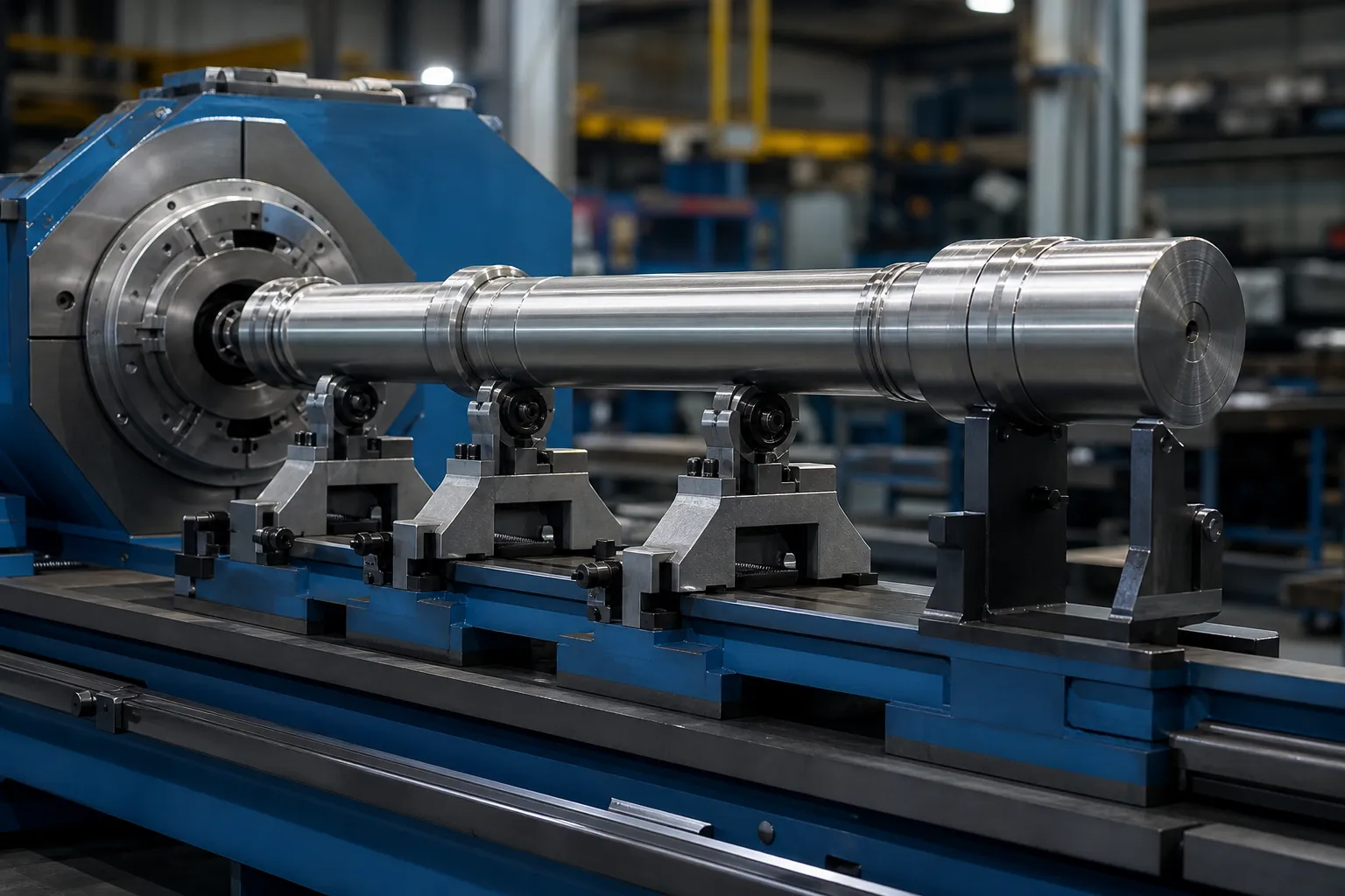
*Illustration des technischen Konzepts. Steifigkeit der Vorrichtung, Sensorposition und Schutz erfordern projektspezifisches Engineering.*
Das kontrollierte Verfahren sollte die Sensoridentifizierung umfassen, Referenz-/Masterprüfung, Montagezustand, Kabelschutz, Nullmethode, Probenorientierung, unterstützen Sauberkeit, Datenerfassungseinstellungen und Datenaufbewahrung. Eine wiederholte Messung an einer instabilen Vorrichtung ist kein Beweis für die Wiederholbarkeit.
Standort synchronisieren, Orientierung und Lektüre
Mehrpunktdaten sind nur dann sinnvoll, wenn jeder Wert einer bekannten Position und Bedingung zugeordnet werden kann. Wenn sich das Teil dreht oder bewegt, Definieren Sie den Encoder/Index, Stationskoordinate, Fahrtrichtung, Verweil- oder Probenahmebedingungen, und was passiert, wenn ein Signal fehlt. Das Ergebnis sollte die rohen oder nachvollziehbaren Quelldaten enthalten, die zur Rekonstruktion der Karte erforderlich sind.
Vermeiden Sie es, eine lokalisierte Spitze zu interpretieren, ohne Sitz und Kontakt zu überprüfen. Tests erneut durchführen, Gegebenenfalls umgekehrte Ausrichtung und wiederholte Basislinienablesungen können ein Teilmerkmal von einer falschen Anzeige unterscheiden.
Choosing Station Count and Placement
How many stations, and where, is a geometry question before it is a budget question. The error modes of slender parts are smooth in space: a bend is a low-frequency curve, so a modest number of stations — placed where the physics says the information lives — reconstructs it well, while doubling the count in uninformative positions buys data volume, not accuracy. Informative positions are predictable: mid-span between supports where a bow reaches its excursion; each stiffness transition on stepped parts, where peaks like to hide; immediately beside functional features whose relationship to the datum matters; and the free ends, which anchor the map. The failure mode of sparse placement is aliasing in its practical form — a short kink sitting between two stations contributes to neither reading cleanly, and a correction aimed at the reconstructed map presses in the wrong place. The honest way to close this risk is not infinite density but a validation: map a set of parts at high density once, confirm that the production station set reconstructs the same peaks and amplitudes, and document that comparison as the station-plan justification.
Turning the Map Into a Correction Decision
The map exists to drive action, and its action vocabulary has three entries: where to press, in which direction, and how hard to expect the part to respond. Peak position and direction come from comparing stations around the maximum; on a part rotating between stations, preserving angular indexing — the synchronization discipline above — is what converts separate readings into a vector, not a pile of magnitudes. Expected response comes from the stiffness story the map already tells: a peak on a heavy section needs a different correction plan than the same amplitude on a thin one, and peaks at stiffness transitions deserve the respect described for separating bend from roundness and setup effects before any press follows. What the map must not do is trigger correction on unverified signals: a localized reading that has not survived a reseat check is a hypothesis, not a peak. That guard rail — map, verifizieren, then correct, with released-state measurement closing the loop — is the same sequence that makes automatische Wellenausrichtung converge in few strokes instead of many.
Mit der Annahme freigegebener Teile korrelieren
Die Messung während des Spannens oder Korrigierens kann zur Prozesskontrolle nützlich sein, Dies beweist jedoch nicht automatisch, dass die freigegebene Welle die Anforderung erfüllt. Vergleichen Sie die Linienmethode mit einer genehmigten Methode für freigegebene Teile an repräsentativen Proben mit normaler Variation. Sehen Messung der Geradheit unter Belastung im Vergleich zur entspannten Messung für die Grenze.
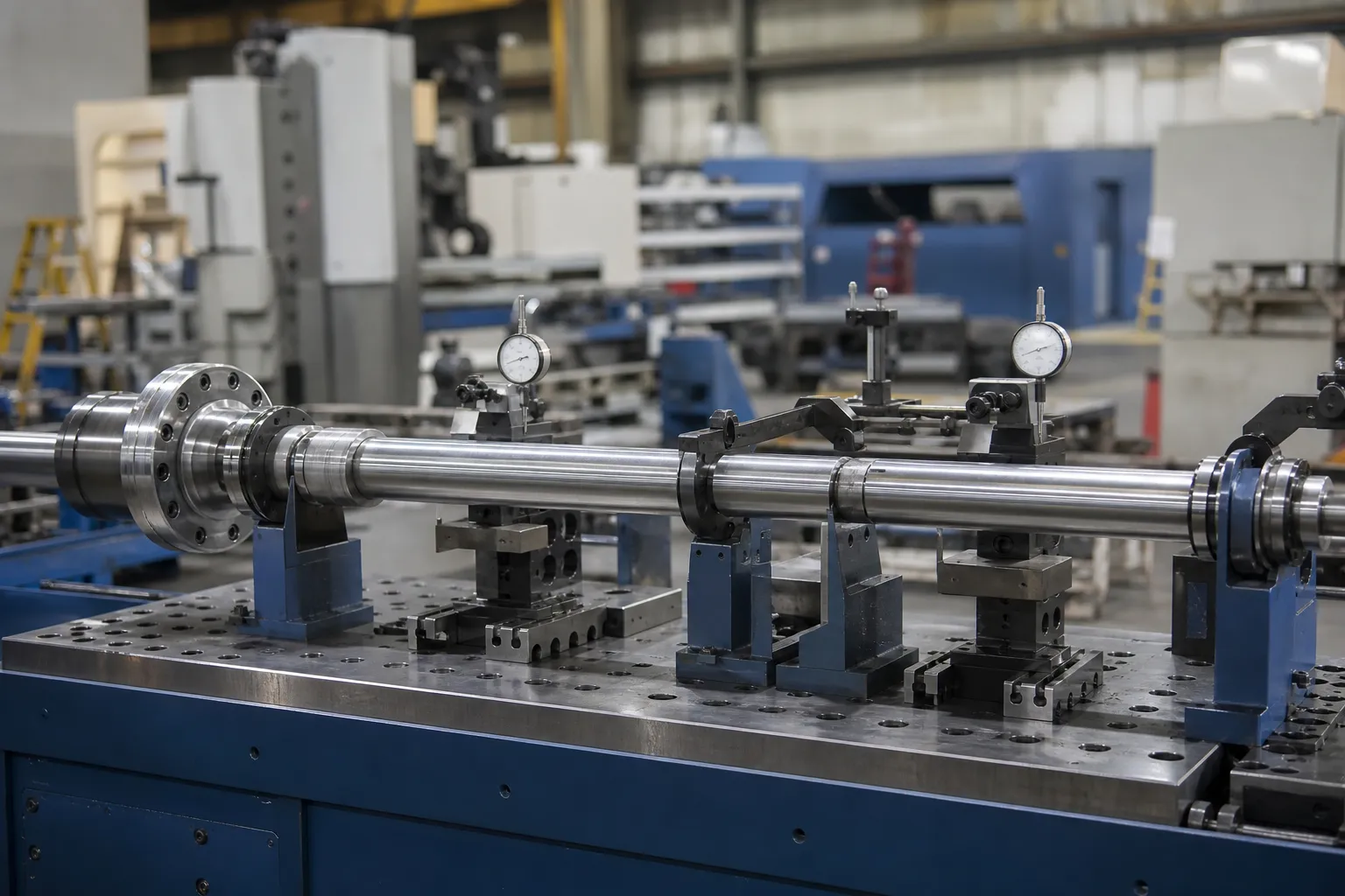
*Illustration des technischen Konzepts. Die Referenzmethode, Stützungen und Abnahmeberechnung müssen durch den genehmigten Qualitätsplan gesteuert werden.*
Ein Korrelationsplan sollte übereinstimmende Stichproben definieren, Blindvergleich, wo sinnvoll, Datums-/Trägeräquivalenz, Kalibrierungsstatus, Vorurteilsüberprüfung, Überprüfung der Wiederholbarkeit/Reproduzierbarkeit, erlaubte Differenz, Eskalations- und Änderungskontrollregeln. Siehe Korrelation zwischen Maschinenmaß und Kundenmaß Und Messgerät R&R zum Begradigen von Linien.
Für eine Messstudie erforderliche Eingaben
Geben Sie die Zeichnung und die Merkmalsdefinition an, bestehende Inspektionsmethode, Teilegeometrie und Bezugsmerkmale, Material-/Herstellungsphase, erwartete Biegestellen, Stichprobenpopulation, Umweltauflagen, gewünschter Datensatz und Kundenakzeptanzmethode. Benutzen Sie die Richtmustertest und Abnahmeanleitung um das Gerichtsprotokoll zu erstellen, Dann Kontaktieren Sie StraighteningTech für ein Bewerbungsgespräch.
Erforderliche Validierung vor einem Systemanspruch
Any multi-point measurement claim needs a defined probe and datum setup, kalibrierte Referenzen, repeated or reseated readings on representative parts, and customer-gauge correlation. A generic machine capability is not a verified result.
FAQ
Does adding more measurement stations automatically improve accuracy?
NEIN. Stations placed where the geometry has information — mid-span peaks, stiffness transitions, functional features, ends — improve the map. Stations added elsewhere add data volume and cost while leaving reconstruction essentially unchanged. Validate the chosen set once against a dense map and document the comparison.
Why do LVDT readings drift over a production shift?
Most often thermal: Sensor, fixture and part expand at different rates as the cell warms, shifting the zero. Mechanical causes come next — bracket compliance, cable pull, tip wear. The control is procedural: a defined zero method and reference-master checks at set intervals, with any shift beyond the procedure’s limit triggering investigation rather than quiet re-zeroing.
Can multipoint LVDT data replace final inspection?
Only through correlation. In-process multipoint data drives the correction loop; the acceptance decision belongs to the released-state method the customer recognizes. When the two have a documented correlation on representative parts, the line method gains standing — until then it is process control, not release.
Verwandte StraighteningTech-Ressourcen
Sehen wie das automatische Wellenrichten funktioniert, Richtmusterprüfung und Abnahme Und Wellengeradheit vs. Rundlauf vs. TIR für generische Kontrollgrenzen, die vor jedem Fähigkeitsanspruch gelten LVDT-Mehrpunkt-Wellenmessung.
Multipoint measurement pays off at acceptance time – pair the FAT-Checkliste mit dem GD&T straightness acceptance guide to agree measurement method and tolerance interpretation in one pass.