
Klikový hřídel je víceosá součást kritická z hlediska únavy, ne konvenční kulatá hřídel. Jeho hlavní ložiskové čepy by měly vytvářet společnou osu otáčení, zatímco každý klikový čep ojnice záměrně sleduje posunutou dráhu. Weby, protizávaží, náporové tváře, zaoblení zaoblení, olejové díry, vlastnosti přídě a příruba setrvačníku ovlivňují měření a bezpečnou dráhu zatížení.
Spolehlivé řešení rovnání klikového hřídele proto musí před výběrem stroje zodpovědět pět otázek:
- Jedná se o sériový klikový hřídel, repasovaný díl nebo oprava malého motoru?
- Která osa hlavního žurnálu a podmínka podpory definují mapu ohybu?
- Je odchylka opravitelným globálním ohybem?, chyba formuláře místního deníku, problém s brusným materiálem nebo prasklina/poškození?
- Jaký tlak, pro materiál a procesní fázi je schválena cesta rovnání válečkem nebo peering?
- Jak bude uvolněná geometrie, celistvost filé, přídavek na broušení a konečné vyvážení je třeba ověřit?
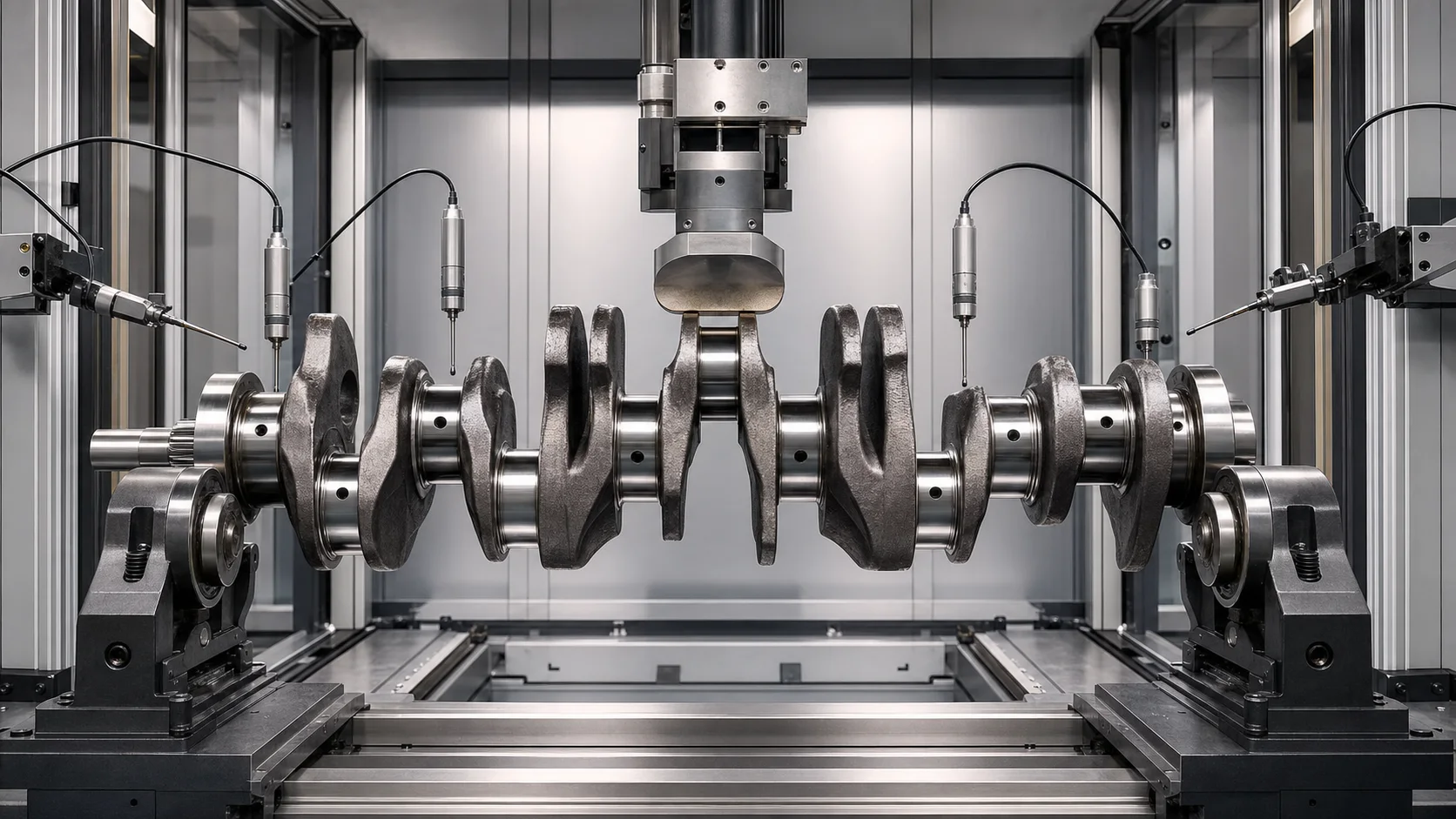
*Inženýrský koncept ilustrace: vícenásobný klikový hřídel podepřený a měřený pro řízenou korekční studii. Nejedná se o fotografii zákazníka. Aktuální kontaktní zóny, limity síly a architektura stroje vyžadují výkresy a reprezentativní vzorky zkoušek.*
Rovnání klikového hřídele není jeden trh
Výsledky DataForSEO pro crankshaft straightening machine zobrazit několik různých záměrů vyhledávání na stejné stránce s výsledky: nástroje na opravu malých motorů, dílenské hydraulické lisy, zařízení na opravu velkých klikových hřídelí a vysoce produkční systémy hlubokého válcování/rovnání válců. Ty by se neměly spojovat do jedné obecné nabídky strojů.
| Rodina klikového hřídele | Typický kontext | Inženýrská cesta |
|---|---|---|
| Kovaný automobilový klikový hřídel | Řízená výroba mezi obráběcími operacemi | Automatizované měření plus validovaný tlak nebo proces rovnání válců |
| Velký diesel, námořní nebo průmyslová kliková hřídel | Nová výroba nebo specializovaná oprava | Těžká manipulace, vícenásobné podpěry a projektová tlaková/válcovací trasa |
| Repase klikové hřídele | Nosit, teplo, historie havárií nebo selhání ložisek | Inspekce, rozhodnutí o broušení a opravě před rovnáním |
| Malá klika motoru s vertikální hřídelí | Trh kompaktních nástrojů pro opravy | Samostatný produkt, upevnění a bezpečnostní obálka |
| Vestavěný nebo lisovaný klikový hřídel | Více sestavených pásů, kolíky a přesahy | Proces vyrovnání sestavy; není to jednodílný recept na kované kliky |
| Klikový hřídel litý nebo z tvárné litiny | Materiálově specifická únava a chování trhlin | Hutnické schválení a omezená korekční studie |
Tato stránka se zaměřuje na jednodílné průmyslové a automobilové klikové hřídele. Malá rovnačka trávníku nebo namontovaná kliková hřídel motocyklu potřebuje jiné řešení.
Definujte anatomii klikového hřídele a referenční řetěz
Technický návrh by měl identifikovat každý funkční prvek:
- všechny hlavní ložiskové čepy a jejich číslování;
- klikové čepy ojnice, zdvih a úhlová fáze;
- stojiny a protizávaží;
- přední nos, načasování, klíčová drážka, drážkové nebo ozubené prvky;
- zadní příruba, pilotní otvor a rozhraní setrvačníku;
- přítlačné plochy a axiální vztažný bod;
- hlavní- a poloměry zaoblení čepů;
- olejové díry, křížové vrtání a vnitřní průchody;
- kalené nebo hluboce válcované oblasti;
- balanční otvory, frézované podložky nebo přidané balanční prvky;
- centra nebo dočasné základny procesu;
- mletý materiál podle deníku a fáze procesu.
Společná osa hlavního žurnálu normálně řídí rozhodnutí o globálním ohybu. Klikové čepy jsou záměrně excentrické a musí být hodnoceny vzhledem k hlavní ose, zdvih a fáze. Hrubý radiální pohyb klikového čepu není přímým důkazem ohnuté hřídele.
Zmrazit fázi výroby nebo opravy
Po kování a hrubém obrábění
Díl může obsahovat měřítko, variace polotovaru a nedokončené základní prvky. Korekce může podpořit následné obrábění, ale měřicí systém musí odlišit odchylku zásoby od skutečného posunutí osy.
Po hlavní- a Pin-Journal Pre-Machining
Funkční žurnálové stopy a počátky procesu jsou k dispozici, zatímco přídavek na broušení zůstává. Hegenscheidt popisuje hluboké válcování a rovnání válců po předběžném opracování, s TIR hlavního ložiska měřeným před výpočtem korekce. To potvrzuje, že fáze procesu a plán zásob jsou neoddělitelné.
Po tepelném zpracování nebo povrchovém kalení
Zbytkový stres, tvrdost a odpružení se mohou změnit. Recept na sílu/posunutí z měkkého polotovaru nelze automaticky přenést na tvrzenou klikovou hřídel. Riziko trhlin a kontrola po procesu se stávají explicitními branami přijetí.
Po hloubkovém válcování filetů
Hluboké válcování se používá k vyvolání zbytkového napětí v tlaku u vysoce zatížených zaoblení. Následná korekční operace nesmí zničit zamýšlený stav zaoblení nebo způsobit nevalidovanou cestu deformace. Tlakový kontakt na zaoblení je zakázán, pokud konstruktér klikového hřídele neschválí vyhrazený proces.
Před konečným broušením
Rovnání může snížit zásobu potřebnou k vytvoření společné osy hlavního žurnálu. Výstupní mapa musí prokazovat, že každý časopis má stále odpovídající přídavek na broušení.
Po konečném broušení
Průměr čepu, kulatost, povrchová úprava, geometrie zaoblení a přítlačné plochy jsou funkční. Kontakt se stává více omezujícím, a cesta přebroušení/opravy/vyřazení může být bezpečnější než další korekce tlaku.
Vrácení servisu nebo renovace
Poškození teplem, zadření ložiska, bodování, praskliny, předchozí broušení, svařování, pokovování nebo předchozí rovnání může změnit riziko. Před použitím síly je vyžadována historie oprav a kontrolní záznam.
| Fáze | Hlavní příležitost | Hlavní riziko | Požadovaný důkaz |
|---|---|---|---|
| Hrubé kování | Snižte nevyváženost obrábění | Variace akcií maskuje geometrii | Kvalifikované procesní údaje a skladová mapa |
| Předem opracované | K dispozici je mapa zatáček s více žurnály | Špatný odkaz na podporu | TIR hlavního deníku a přídavek na broušení |
| Tepelně zpracované | Opravte zkreslení tepelného zpracování | Odpružení a iniciace cracku | Zkoušky materiál/tvrdost a síla-posun |
| Hluboko válcované | Koordinujte proces házení a pevnosti zaoblení | Poškození kompresního stavu zaoblení | Schválení vlastníka procesu a ochrana zaoblení |
| Povrchová úprava | Záchrana v rámci finální geometrie | Poškození povrchu/tvaru a ztráta zásob | Úplná kontrola žurnálu/zaoblení a limit oprav |
| Vrácení služby | Obnovte opravitelnou součást | Skrytá únava, poškození teplem nebo předchozí opravou | NDT, dějiny, skladová a dispoziční pravidla |
Oddělte hlavní žurnály od Offsetových klikových čepů
Marposs popisuje měření klikového hřídele, které měří jak průměry hlavního čepu rotujícího kolem hlavní geometrické osy, tak průměry čepu čepu po orbitální dráze kolem této osy.. Toto je základní požadavek na oddělení signálu.
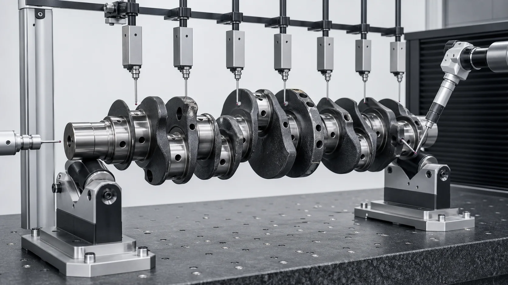
*Inženýrský koncept ilustrace: mapa ohybu hlavního žlabu a geometrie odsazeného klikového čepu vyžadují samostatné měřicí stopy. Skutečná umístění sond, rotační model a masky prvků se řídí výkresem a plánem korelace měřidel.*
| Měřicí dráha | Co zakládá | Běžná chyba při nesprávném použití |
|---|---|---|
| Všechny hlavní časopisy | Mapa házení a ohybu společné osy | Lokální lobing je interpretován jako globální ohyb |
| Přední a zadní hlavní čepy | Opěrná/referenční osa | End damage zkresluje celou mapu |
| Kliky | Průměr, obíhat, vztah zdvihu a fáze | Záměrná excentricita je interpretována jako házení |
| Nárazové tváře | Axiální umístění a čelní házení | Čtení dominují otřepy nebo místní opotřebení |
| Přední nos a zadní příruba | Vztah připojených komponent | Chyba funkce je považována za ohyb hřídele |
| Kulatost/válcovitost čepu | Místní forma | Nízká hodnota TIR skryje lokální chybu formuláře |
| Oblasti filetů a olejových děr | Stav konstrukce a povrchu | Chybí vada kritická pro únavu |
| Roviny korekce rovnováhy | Stav osy hmoty | Rovnováha je mylně považována za geometrickou přímost |
Systém měření klikové hřídele Nidec samostatně třídí vnější průměry čepů a čepů. Marposs také podporuje finální nebo mezioperační rozměr, geometrické a nedestruktivní měření. Přenosná lekce není hodnotou přesnosti soutěžícího; je to potřeba víceznakového kontrolního plánu založeného na výkresech.
Vyberte Correct Support Reference
Házení klikového hřídele lze měřit:
- mezi kvalifikovanými centry;
- na konci hlavních deníků;
- na vybraných V-válcích;
- v podpěrách ekvivalentních ložiskům;
- v brusce nebo speciálním nastavení měřidla.
Hegenscheidt uvádí měření házivosti odkazované na středy nebo V-bloky. Tato nastavení automaticky neposkytují stejné výsledky. Řešení by mělo definovat:
- deníky fyzické podpory a souřadnice;
- stav střediska a způsob kvalifikace;
- kompenzace zaoblení deníku;
- axiální omezení a povolený pohyb;
- úhel kliky a úhlové indexování;
- gravitační prověšení pro velké klikové hřídele;
- senzor síly a masky prvků;
- opakovatelnost uvolněného stavu;
- korelace s bruskou a měrkou zákazníka.
Stroj nesmí měnit počátky uprostřed korekční smyčky bez zavedené transformační a korelační studie.
Tlak, Rovnání rolí a peening jsou různé procesy
Řízené tlakové rovnání
Lis aplikuje lokalizované tříbodové nebo vázané zatížení ve schválené oblasti hlavního deníku. Těžká opravárenská zařízení Gleason demonstrují jednu tržní cestu podpory, přidržovače nad hlavou a pohyblivý beran lokalizují práci kolem vybraného žurnálu. Přesné rozložení a kapacita konkurenta nejsou specifikací StraighteningTech.
Vyžaduje tlakové vyrovnání:
- ověřená diagnóza globálního ohybu;
- schválenou cestu načítání přes žurnály/weby;
- širokoúhlé kontaktní nástroje;
- silové a posuvné stropy;
- odrazová charakteristika;
- úplné vyložení před převzetím;
- poopravné kontroly trhlin a povrchů.
Rovnání rolí
Hegenscheidt kombinuje hluboké válcování závislé na úhlu, měření TIR hlavního ložiska a rovnání válců. Jedná se o výrobní technologii spojenou s úpravou zaoblení a geometrií předbroušení. Neměl by být popisován jako obecný víceválcový rovnač tyčí.
Peening
SERP opravárenského trhu také ukazují metody peeningu. Peening mění místní zbytkové napětí a vyžaduje samostatný kvalifikovaný pracovní návod, ovládací prvky operátora, povrchová pravidla a kontrola. Nejedná se o automatickou náhradu tlakového rovnání, a tento článek netvrdí univerzální recept na peening.
| Metoda | Potenciální fit | Primární ovládání | Nepředpokládejte |
|---|---|---|---|
| Tlakové vyrovnání | Schválený holý klikový hřídel s bezpečnou dráhou zatížení | Platnost, přemístění, rozpětí podpory a uvolněné TIR | Hotové filety/žurnál tolerují kontakt |
| Rovnání rolí | Výrobní proces integrovaný s operacemi žurnálu/zaoblení | Úhlově závislá rolovací mapa a mapa hlavního deníku | Stejné nástroje se hodí pro každou rodinu klik |
| Peening | Specializovaná metoda opravy | Umístění, intenzita, zbytkové napětí a kontrola povrchu | Zatloukání je ze své podstaty bezpečné nebo opakovatelné |
| Broušení | Místní tvar/průměr a omezená excentricita na skladě | Geometrie žurnálu a úběr materiálu | Broušení může odstranit každý globální ohyb |
| Nahrazení/odmítnutí | Crack, hořet, nedostatečné zásoby nebo nebezpečná cesta nákladu | Inženýrská dispozice | Každý ohnutý klikový hřídel je opravitelný |
Vytvořte chráněnou kontaktní mapu
Výchozí zóny bez stisknutí a bez podpory
- hlavní- a poloměry zaoblení čepů;
- olejové otvory a křížové vrtání;
- vyosené klikové čepy, pokud je neschválí vyhrazená trasa;
- přítlačné plochy a hotové plochy přírub;
- drážky, splajny, vlákna a funkce časování;
- vyvažovací otvory a prvky lokální korekce hmoty;
- ostré přechody webů a tenké hrany protizávaží;
- hluboce válcované, indukčně kalené, nitridované, svařované, pokovené nebo opravené oblasti;
- popraskané, spálený, rýhované nebo tepelně ovlivněné povrchy;
- hotové čepy bez chráněného schválení nástroje.
Potenciálně schválené zóny
- hrubé nebo polotovary hlavních deníků s odpovídající zásobou;
- procesní límce nebo obětní nástavce;
- cesty zatížení webu/časopisu schválené návrhářem;
- vyhrazená místa valivého kontaktu definovaná výrobním procesem.
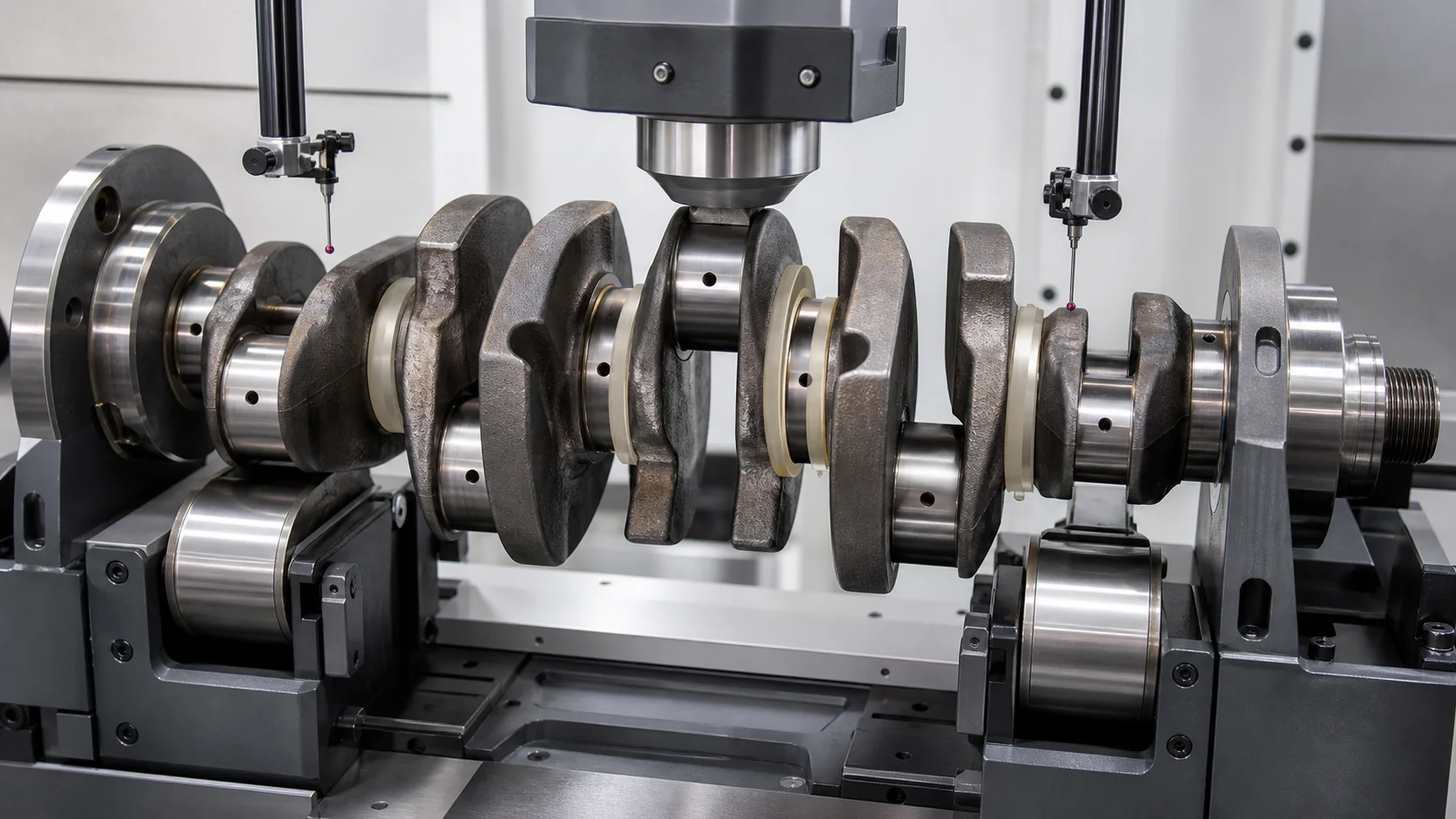
*Inženýrský koncept ilustrace: korekce je omezena na schválenou dráhu zatížení hlavního žurnálu při zaoblení, olejové díry, klikové čepy a přítlačné plochy zůstávají chráněny. Obrázek neautorizuje tato umístění pro skutečnou součást.*
Mapa bezpečného kontaktu by měla být uložena podle čísla dílu a revize výkresu. Čep, který je bezpečný před broušením, se může později stát chráněným finálním povrchem.
Řízení odpružení a křížové spojky
Korekce na jednom hlavním čepu změní elastický tvar sousedních žeber a čepů. Proces by měl používat úplnou mapu ohybu hlavního deníku spíše než pronásledovat jeden vrchol indikátoru.
Pro každý opravný krok:
- otočte a změřte všechny řízené hlavní čepy;
- oddělit lokální formu od středového posunutí;
- identifikovat korekční souřadnice a úhel kliky;
- použít ověřené přírůstkové zatížení;
- rekordní síla a výtlak;
- zcela vyložit;
- otočte a přeměřte celou mapu;
- zkontrolujte sousední klikové čepy, tah/příruba a chráněné povrchy;
- zastavit na abnormální ztuhlosti, indikace neopakovatelnosti nebo kontroly.
Zatížený posun není konečným výsledkem. Pouze uvolněná a opakovaná mapa může určit, zda bylo odpružení bezpečně kompenzováno.
Rovnání vs broušení
Broušení může generovat průměr čepu, kulatost, válcovitost a povrchová úprava. Může také odstranit omezenou excentricitu, zatímco zásoby zůstávají. Nelze předpokládat obnovení společné osy hlavního žurnálu, pokud by požadovaný odběr materiálu porušil velikost, filé nebo limity tvrdosti.
Rozhodnutí vyžaduje skladovou mapu žurnálu po žurnálu:
- vstupní průměr a házivost;
- minimální hotová velikost;
- zbývající tvrdá vrstva nebo opravný nátěr;
- povolená poddimenzovaná/třída opravy;
- geometrie zaoblení a přítlačné plochy;
- podpora brusky a nastavení vztažného bodu;
- očekávaná zásoba po uvolněném narovnání.
Průběžné brousicí měřidla Marposs ukazují, že průměry hlavního a čepového čepu mají odlišné požadavky na pohyb a měření. Rovnání a broušení by proto měly být plánovány jako spojené, ale oddělené operace.
Rovnání vs vyvažování
Vyvážení klikového hřídele koriguje rozložení hmoty vzhledem k definovaným korekčním rovinám a, v aplikacích motoru, mohou být spojeny s předpoklady hmotnosti a rotující/vratně se pohybující hmotnosti. Nekoriguje souosost hlavního deníku, tvar pin-journal nebo ohnutá globální osa.
Pokud rovnání, broušení, vrtání, frézování, svařování, po vyvažování dochází k pokovování nebo úběru materiálu, podmínka konečné rovnováhy musí být znovu ověřena. Klikový hřídel může projít geometrickým házením a přesto nesplní požadavek na vyvážení, nebo projít vyvážením, když je hlavní čep geometricky posunut.
Crack, Inspekce citlivá na povrch a únavu
Dosažení cíle házení není dostatečné, pokud korekce přináší škodlivé indikace nebo poškozuje povrch kritický z hlediska únavy. Plán kontrol by měl definovat:
- předčištění a vizuální kontrola;
- magnetické částice, vířivými proudy nebo jinou schválenou cestou NDT materiálem/procesem;
- pokrytí filetů a olejových otvorů;
- deník dent, otlaky a limity povrchové úpravy;
- kontrola broušení-popálení nebo tepelného poškození;
- v případě potřeby kontroly tvrdosti/hloubky;
- kritéria přijatelnosti pro předchozí svar, pokovování nebo oprava;
- načasování kontroly před a po korekci/broušení;
- inženýrská dispozice pro hraniční indikace.
Hegenscheidtovo procesní tvrzení týkající se zachování únavové pevnosti patří k jeho ověřenému systému válcování. Bez našich vlastních vzorků to nelze přenést na návrh tlakového rovnání, schválení materiálu a validace citlivá na únavu.
Proces rovnání klikového hřídele v uzavřené smyčce
1. Identifikujte část
Načtěte správný recept z čísla klikového hřídele, rodina motorů, materiál, fázi procesu, historie revizí a oprav výkresů.
2. Zkontrolujte a vyčistěte
Vyčistěte čepy a pomocné plochy. Zkontrolujte olejové otvory, filé, povrchy čepů, weby, nos a příruba. Dokončete požadované předzpracování NDT.
3. Kvalifikujte nastavení počátku
Ověřte střediska nebo podpůrné deníky, axiální umístění, opakovatelnost rotace a sezení.
4. Sestavte mapu pro více časopisů
Změřte každý hlavní čep rotací. Záznam pin-žurnálu, tah, charakteristiky nosu a příruby samostatně, kde je to požadováno.
5. Klasifikujte odchylku
Oddělte globální ohyb od drážkování, kužel, chyba broušení, chyba fáze/zdvihu klikového čepu, poškození příruby, crack, tepelné zkreslení nebo nerovnováha.
6. Vyberte Schválenou metodu a cestu načtení
Zvolte tlak, válcování, peening, broušení nebo vyřazení podle schváleného postupu dílu. Potvrďte všechny chráněné zóny.
7. Použít přírůstkovou korekci
Kontrolní síla, přemístění, úhel kliky a poloha nástroje. Zastavte při abnormální reakci.
8. Uvolněte a znovu změřte
Zcela vyložte a znovu otočte klikovým hřídelem. Místo kontroly pouze opravené polohy aktualizujte úplnou mapu hlavního deníku.
9. Zkontrolujte a nasměrujte po proudu
Proveďte následné korekce NDT/kontroly povrchu a potvrďte brusný materiál. Cesta k broušení, konečné změření, kontrola vyvážení a montáže.
10. Zaznamenejte výsledek
Identita obchodu, revize receptury, nastavení vztažného bodu, mapy před/po, korekční souřadnice, křivky síla-posun, alarmy, kontrola a dispozice.
Navrhovaná buňka pro vyrovnání klikového hřídele
Systém může zahrnovat specifický projekt:
- elektromechanická nebo hydraulická korekční jednotka dimenzovaná na základě testování vzorku;
- nastavitelné válečky hlavních žlábků, středy nebo V-podpory;
- otáčení serva a indexování úhlu kliky;
- více senzorů házení pro mapu hlavního deníku;
- samostatný klikový čep, tah, moduly pro měření nosu a příruby;
- široké vyměnitelné lisovací patky a chráněné podpěry;
- automatická logika zachování pro filety, olejové otvory a protizávaží;
- monitorování síly/posunu a kompenzace odpružení;
- zatížení těžkých dílů, bezpečnost zvedání a proti převrácení;
- kontrola receptury, sledovatelnost a export dat o kvalitě;
- rozhraní k broušení, NDT a bilanční záznamy.
Konfigurace pro malý automobilový klikový hřídel není automaticky vhodná pro velký lodní klikový hřídel nebo díl z dílny.
Vzorový plán testování a akceptace
Reprezentativní vzorky by měly zahrnovat:
- nejmenší a největší délka klikového hřídele, houpačka, hmotnost a průměr čepu;
- různé počty hlavních deníků, zdvihy klikového čepu a rozložení protizávaží;
- kovaný, lité a schválené podmínky opravy;
- hrubý, předem opracované, tepelně zpracované, hluboce válcované a povrchově broušené stupně;
- extrémy materiálu a tvrdosti;
- očekávané tvary příchozích ohybů a úhly klik;
- vzorky chyb formuláře deníku, které by neměly spustit opravu;
- minimální brusný materiál;
- schválené a zakázané kontaktní zóny;
- síla/posun a obálka odpružení;
- cross-coupling přilehlých žurnálů;
- korelace hlavního deníku a klikového čepu;
- před/po NDT a výsledky povrchu;
- konečné broušení a ověření vyvážení;
- opakovatelnost a směrování NOK.
Použijte Příručka pro testování a přijímání vzorků narovnání oddělit proveditelnost, TUK, SAT a produkční schopnost.
Údaje požadované pro technický návrh
Uveďte prosím:
- výkres a revize klikového hřídele;
- rodina motoru/aplikace a klikového hřídele;
- jednodílná kovaná/litá nebo montovaná konstrukce;
- materiál, tepelné zpracování, tvrdost a zpracování filé;
- aktuální fázi výroby nebo opravy;
- hlavní deník, klikový čep, tah, rozměry nosu a příruby;
- mrtvice, rozložení fáze kolíku a protizávaží;
- mapa ropných děr a vnitřních průchodů;
- příchozí mapa náběhu hlavního deníku podle úhlu;
- kulatost deníku, válcovitost a kuželovitost;
- výkresové údaje a nastavení zákaznických měření;
- schválené podpůrné/opravné zóny a zakázané prvky;
- broušení podle deníku;
- crack, hořet, kritéria přijatelnosti povrchu a oprav;
- následné broušení, sled vyvažování a montáže;
- požadavky na zprávy a sledovatelnost;
- reprezentativní vzorky pro zkoušky.
Často kladené otázky
Lze narovnat klikový hřídel?
Některé klikové hřídele lze korigovat, ale proveditelnost závisí na materiálu, konstrukce, fázi procesu, tvar ohybu, brusný materiál, stav zaoblení a bezpečnou dráhu zatížení. Prasklina, tepelně poškozený deník nebo nedostatečné zásoby mohou vyžadovat opravu nebo vyřazení.
Jak poznáte, že je klikový hřídel ohnutý?
Změřte všechny hlavní čepy v kvalifikovaném nastavení podpory a oddělte místní zaoblení od posunutí středu. Orbitální pohyb klikového čepu, Funkce házení axiálního čela a příruby/čela vyžadují samostatné dráhy.
Můžete stisknout kliku nebo filet?
Nepředpokládejte, že ano. Klikové čepy jsou offsetové prvky a zaoblení jsou kritická z hlediska únavy. Výchozí mapa kontaktů chrání kliky, filé, olejové otvory a hotové přítlačné plochy, pokud není schválen speciální proces.
Je peening lepší než lisovací rovnání?
Jsou to různé procesy zbytkového napětí a korekce. Správná trasa závisí na konstrukci klikového hřídele, materiál, fázi výroby/opravy a ověřené pracovní pokyny. Ani jeden by neměl být vybrán z obecného internetového postupu.
Broušení plechovky Odstraňte ohyb klikového hřídele?
Broušení může odstranit omezenou excentricitu v rámci přídavku na zásobu a vygenerovat konečný formulář deníku. Nemůže bezpečně vyřešit každou chybu společné osy. Použijte mapu zásob žurnálu po žurnálu.
Je stále nutné vyvažování klikového hřídele?
Ano, když je uvedeno. Rovnání koriguje geometrii; vyvažování koriguje rozložení hmoty. Znovu ověřte vyvážení po jakékoli operaci, která změní geometrii nebo hmotnost.
Měl by být zkontrolován servisní klikový hřídel na praskliny?
Ano, podle materiálu, standardní opravy a požadavky zákazníka. Rovnání se nesmí používat ke skrytí trhliny, hořet, záchvat nebo stav předchozí opravy.
Vybudujte řešení kolem osy hlavního žurnálu
Vyvíjíme řešení pro rovnání klikových hřídelů podle skutečné rodiny klik, datum hlavního deníku, ofsetová geometrie klikového čepu, fázi procesu, chráněné filety, bezpečná cesta nákladu, uvolněná mapa zatáček, brusný materiál a sled závěrečné kontroly. Architektura stroje se řídí důkazy z výkresů a zkušebních vzorků – nikoli obecným receptem hřídele nebo specifikací konkurence.
Next steps for a crankshaft project: potvrdit koncepci stroje s hřídel, průvodce výběrem rovnačky trubek a profilů, poté zarámujte obchodní případ s cost structure of a straightening machine.
Pošlete výkres klikového hřídele, fázi procesu, hmotný stav, mapa příchozího deníku, přídavek na broušení, kontrolní standard a reprezentativní vzorky. Poté můžeme definovat strategii měření, tlaková nebo válcovací dráha, nástrojová mapa, korekční obálku a sledovatelný přejímací plán pro vaši aplikaci klikového hřídele.
Související: Rovnání vačkového hřídele se řídí stejnou logikou základny – viz řešení pro rovnání vačkového hřídele.