
Въртящата се индикаторна следа може да съдържа няколко ефекта наведнъж. Може да отразява оста на детайла, локална закръгленост, цилиндрична форма, данъчна връзка, опора за сядане, грешка на приспособлението, настройка на сондата или прекъсната функция. Наричането на всяко високо показание „огъване“ може да доведе до грешно коригиращо действие и да повреди част, която всъщност се нуждае от измерване или преглед на обработка.
Това ръководство обяснява как да диагностицирате сигнала преди да вземете решение за изправяне. Той не установява измервателна система StraighteningTech, толерантност, резолюция на сензора, процедура за изходна точка или възможност за корекция. Контролираният чертеж и методът на проверка от клиента са необходими за окончателни решения.

*Илюстрация на инженерна концепция. Това показва, че въртящ се сигнал може да включва вариация на формата; това не е резултат от измерване за клиентска част или предписана инспекционна настройка.*
Назовете характеристиката, преди да прочетете измервателния уред
Заоблеността описва състояние на формата на напречното сечение. Извивката на оста описва пространствения път на референтна ос. Runoout е въртящо се измерване спрямо настройка на еталон и може да включва множество участници. Коаксиалност, концентричността и цилиндричността също имат различни определения и изисквания за проверка. Чертежът трябва да идентифицира коя характеристика контролира приемането.
| Сигнал или характеристика | Диагностичен въпрос |
|---|---|
| Закръгленост / лобинг | Местният радиус променя ли се при въртене на секцията? |
| Огъване на оста | Референтната ос променя ли позицията си по дължината? |
| Изтичане | Коя дата, опорите и сондажната станция създават отчитането? |
| Коаксиална връзка | Дали множество функции се сравняват с дефинирана обща ос? |
| Сигнал за приспособление | Повторното поставяне или промяната на ориентацията на опората променя ли резултата? |
Вижте изправеност на вала, изтичане и ТИР и коаксиалност срещу биене за свързана терминология.
What a Rotating Trace Is Made Of
A probe reading taken while a part rotates is, mathematically, a mix of components that repeat once, twice, three times and more per revolution. Reading the mix is the core diagnostic skill. A once-per-rev component means the surface is, on average, further from the rotation axis on one side than the other — which is the signature of either an axis offset between the part’s reference geometry and the rotation axis, or of a bent axis displacing the section as a whole. A twice- or three-times-per-rev component means the section is oval or lobed: the local radius itself changes around the circumference, a form condition of the cross-section that no amount of axis correction removes. Higher-frequency content usually reflects surface texture, keyways and interrupted features, or vibration entering through the supports.
The decisive separation between the two once-per-rev causes is axial. A true bend displaces different stations by different amounts and often in different directions, so the once-per-rev component’s amplitude and phase change as the probe moves along the part. A pure eccentricity condition — centers offset, seat offset, chuck runout — produces a once-per-rev component that keeps the same phase and proportional amplitude at every station. One trace at one station cannot distinguish them; a short axial map routinely can. That is the reasoning behind the multi-station discipline above, and behind multipoint measurement arrangements that read several stations in one setup.
Where Lobing Comes From
Lobing is rarely random — it carries the fingerprint of the machining that produced the surface, which is what makes it diagnostic. Three-lobe out-of-roundness is the classic signature of parts ground on centerless machines, where the part floats between wheel, regulating wheel and blade and the geometry locks into a three-point stability condition. Even-lobe ovality traces back to opposing clamping or distortion relieved after machining — a thin sleeve released from a chuck, a part that relaxed after heat treatment. Odd lobing beyond three appears with certain workholding arrangements and with relapsing of interrupted cuts. Knowing the part’s process route therefore tells you what lobing to expect and whether an observed lobe count is a workpiece reality or an artifact of the current setup: a lobe count that changes when the part is reseated in different orientations is being generated by the setup, not the part.
Първо проверете датата и настройката
Преди да интерпретирате частта, проверете характеристиките на центъра, дневници или други референтни повърхности, условие за поддръжка, чистота, контакт на сондата, ротационен метод и аксиална станция. Повреден център, брус, мръсна седалка, неправилен контакт на опора или сонда върху прекъсната повърхност може да създаде видимо биене, което не представлява огъване на оста.
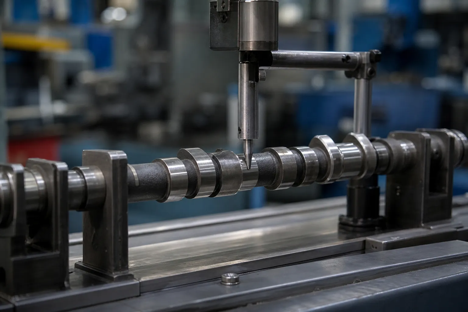
*Илюстрация на инженерна концепция. Той илюстрира измерване на дневник, съобразено с характеристиките; действителни данни, следите на сондата и ъгловите маски зависят от контролирания детайл.*
Използвайте проверка за повторно поставяне/повторение и сравнете няколко станции. Ако следата се промени значително след повторение на настройката, проучете реализацията на приспособлението или опорната точка, преди да приложите коригираща сила.
Сравнете множество станции и ориентации
Завоят на оста обикновено изисква аксиална карта. Локална закръгленост или лобинг може да се появи на една станция, но не и на друга. Едно общо отчитане на индикатора в един момент не може да докаже кой сътрудник доминира. Запишете местоположението на станцията, ориентация, референтно състояние и следа или изчислен резултат, изискван от процедурата за приемане.
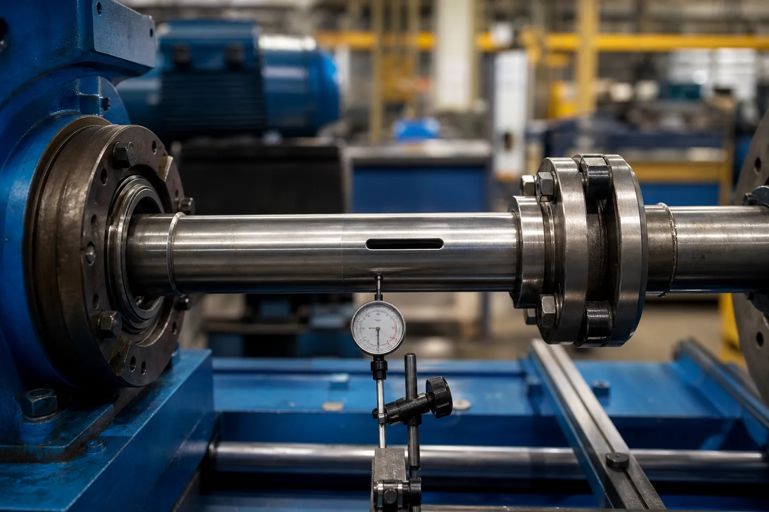
*Илюстрация на инженерна концепция. Той представлява въпрос за ротационно измерване с много функции, не е одобрено приспособление или заключение, че наблюдаваният сигнал е огънат.*
Separating Spindle Error From Part Error
On any rotating instrument, the reading contains the part’s geometry plus the rotation error of the instrument itself — spindle runout, bearing wander, support eccentricity. Precision metrology has standard separation techniques for this, and their logic is worth knowing even when the full apparatus is not available. Reversal methods measure the part in one orientation, then rotate the part exactly half a revolution relative to the fixture and measure again: part error keeps its sign in part coordinates while setup error keeps its sign in machine coordinates, so combining the two traces separates them. Multistep methods extend the same idea through a series of indexed orientations. On a production straightening machine, the practical descendants are simpler: reseating the part in a different clocking orientation and checking whether the trace rotates with the part or stays fixed in the machine tells most of the story, and comparing readings before and after swapping a support identifies which element contributes what.
These checks cost minutes and prevent the most expensive mistake on this page: correcting a bend that lives in the bench. They also make the eventual correlation to the customer gauge meaningful, because both sides of that comparison are then measuring parts rather than setups — the premise underlying измервателен уред Р&R studies on straightening lines.
A Practical Diagnostic Sequence
The checks above assemble into a fixed order of operations that experienced lines follow before any correction decision. Първо, clean and inspect the seating features — centers, списания, support vee blocks — for damage, burrs and debris, since the cheapest explanation is always the setup. Второ, take a trace, reseat the part in the same orientation, and retrace: disagreement beyond the setup’s established repeatability stops the investigation at the fixture. трето, reseat in a rotated orientation: a trace that follows the part is a part signal; one that stays fixed in the machine is a machine or fixture signal. Fourth, map at least three stations along the length and note how the once-per-rev component’s amplitude and phase behave: varying amplitude and rotating phase indicate bend; constant phase with proportional amplitude indicates eccentricity. Fifth, look at the lobe content in relation to the part’s machining history before believing any form conclusion. Only then choose the response — correction for confirmed axis bend within approved zones, or the alternative routes for everything else, with the released-state condition treated per loaded versus released measurement.
The sequence exists because each step filters a class of false positives that would otherwise survive to the next. Skipping ahead to correction is how parts get pressed for eccentricity fixtures, ovality and chucking artifacts — damage that no later measurement undoes.
Изберете отговора от диагнозата
Ако доказателствата подкрепят състояние на огъване на ос и има одобрени контактни/подпорни зони, кандидат за трасе за изправяне може да бъде оценен чрез пробен тест. Ако сигналът е предимно закръгленост, прекъсната геометрия, проблем с данни, грешка на приспособлението или връзка на отделна характеристика, може да се наложи различен процес или инспекционен преглед. Не използвайте изправяне, за да компенсирате проблем с измерването.
За контролирана локална корекция, виж точково изправяне. За съответствие с окончателния метод на проверка, see machine gauge versus customer gauge correlation.
Валидирайте с Customer Gauge
Примерният план трябва да включва известни/референтни условия, когато има такива, повторете настройката, множество станции, измерване на изпуснато състояние, идентификация на части и приспособления, запазване на необработени данни и корелация на клиента. Резултатът трябва да посочи коя характеристика е оценена и кои несигурност или ограничения на настройката остават.
ЧЗВ
Високият TIR винаги ли означава, че валът е огънат?
не. TIR може да включва данни, закръгленост, приспособление и други сътрудници. Първо диагностицирайте настройката и няколко станции.
Може да коригира закръглеността?
Не като общо заключение. Закръглеността е различно геометрично състояние и може да изисква различен процес или път на проверка.
Защо да повтаряте настройката?
Повторното четене след повторно поставяне помага да се разграничи сигналът на детайла от опората, вариация на еталон или приспособление.
What does a three-lobed trace usually indicate?
Most often, a surface produced by centerless grinding, where the three-point contact of wheel, regulating wheel and blade locks the section into a three-lobe form condition. It is a cross-sectional form issue, not an axis issue, and it should be verified against the part’s machining history before any response is chosen.
How can I tell eccentricity from bend with one probe?
Move the probe along the part and watch the once-per-rev component. Bend shows varying amplitude and shifting phase between stations; eccentricity keeps the same phase and proportional amplitude everywhere. If the probe cannot move, mapping several stations with a moved setup achieves the same separation at the cost of reseating discipline.
Does reseating the part in a different orientation really separate machine error?
да, in its simplest form. Part error rotates with the part; machine and fixture error stay fixed in machine coordinates. Comparing traces at two clockings shows which class dominates the reading. Formal reversal and multistep methods refine the same principle when numbers, not just classification, са задължителни.