
On the drawing, straightness is one symbol: a short horizontal line in a feature control frame. On the shop floor, that single symbol has to survive a journey — from the designer’s intent, through the measuring strategy, to the final accept/reject decision at the straightening machine. When any step of that journey is misunderstood, the result is the same: parts argued over, tolerances impossible to hold, and a straightness spec that means something different in the drawing office than it does at inspection.
This guide walks through GD&T straightness as defined by ASME Y14.5 — from the drawing callout to the acceptance decision — with special attention to the points that matter most in shaft and tube straightening.
First Decision: What Is the Callout Actually Controlling?
Straightness is unique among GD&T characteristics: it is the only form control that can apply either to a surface line or to the axis of a feature of size. These are two different controls with different tolerance zones, different measurement methods and different acceptance logic. Everything downstream depends on which one your drawing means.
Surface straightness
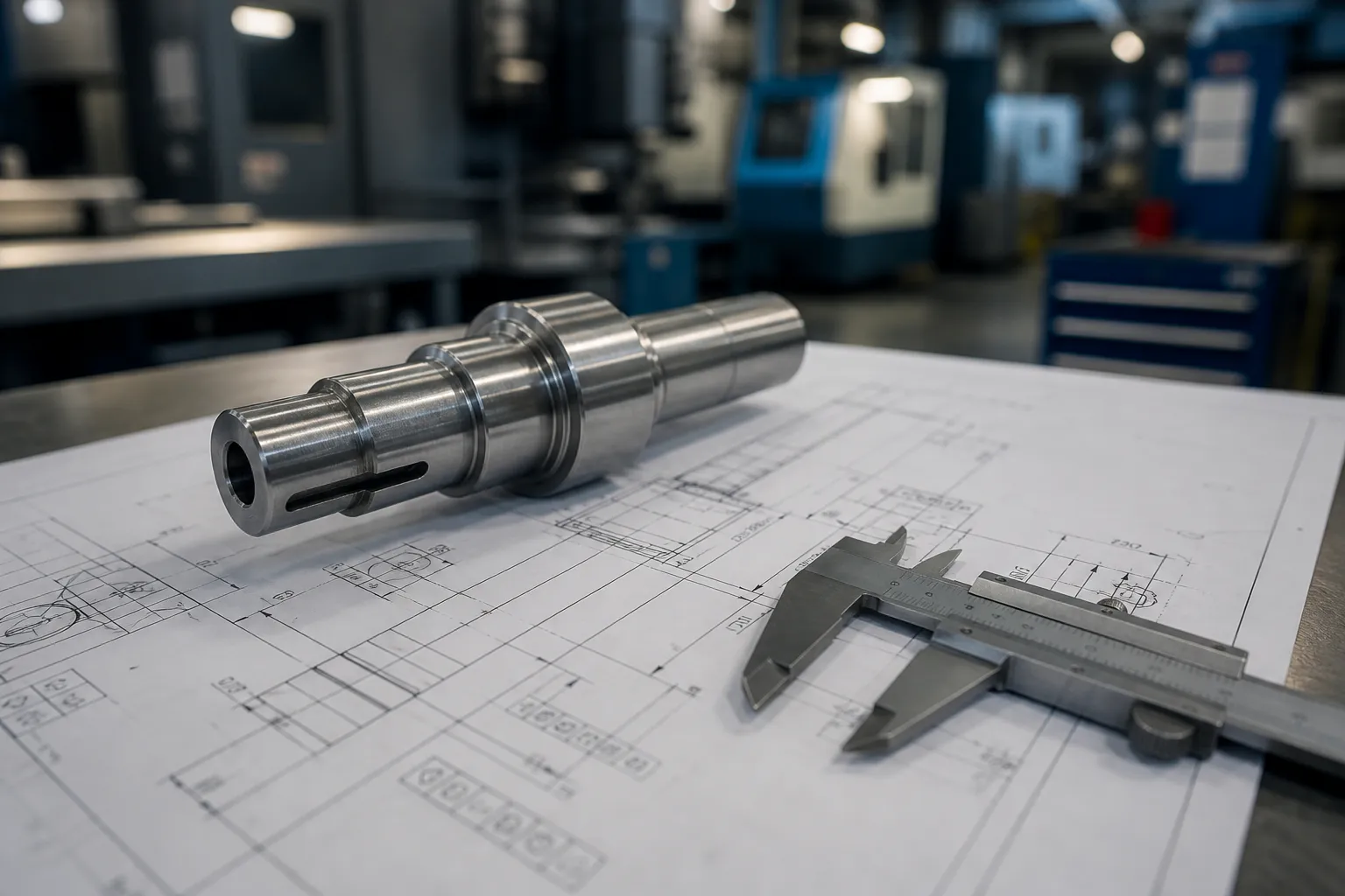
- Những gì nó kiểm soát: the form of a line element on a surface — on a flat surface, or on the axial line elements of a cylinder.
- Tolerance zone: two parallel lines, separated by the tolerance value, within which each surface line element must lie.
- How it is called out: the feature control frame attaches to the surface (with a leader or extension line), not to a size dimension.
- Datums: none. Straightness is a form control — it controls the shape of the feature itself and is not referenced to any datum.
Axis (derived median line) sự thẳng thắn
- Những gì nó kiểm soát: how much the derived median line — the line joining the center points of the cross-sections — may deviate from a straight line.
- Tolerance zone: a cylinder (when the diameter symbol is used in the frame) centered on the true axis; the derived median line must stay inside it.
- How it is called out: the feature control frame attaches to the size dimension of the feature — the diameter dimension of the shaft. This placement is the signal that the axis, not the surface, is controlled.
- Material condition modifiers: unlike surface straightness, axis straightness may be specified at MMC (maximum material condition) or LMC, which enables bonus tolerance — a point we return to below.
Reading the Feature Control Frame
The feature control frame is read left to right:
- Geometric characteristic: the straightness symbol (a horizontal line).
- Tolerance zone shape and value: optionally the diameter symbol (Ø — meaning a cylindrical zone, only applicable to axis control), the tolerance value, and any material condition modifier (Ⓜ for MMC, Ⓛ for LMC).
- Datums: for straightness, this compartment is empty — form controls do not reference datums.
Two frames that look almost identical can mean different things: “straightness 0.1” attached to the surface is a 0.1 wide two-line zone on each surface element; “Ø straightness 0.1” attached to the diameter dimension is a 0.1 diameter cylinder around the axis. Same symbol, same number, different part acceptance.
Straightness and Rule #1 (the Envelope Principle)
Under ASME Y14.5, unless otherwise specified, Rule #1 applies: the perfect form of a feature is required at MMC — the form error of a feature of size may not exceed its size tolerance when the feature is at maximum material. In plain terms:
- A shaft at its maximum diameter must have near-perfect form; as the diameter departs from MMC toward LMC, form freedom grows with the size departure.
- Refining form beyond what Rule #1 already guarantees is exactly what a straightness callout on a feature of size does — it overrides the default and imposes a specific, stated form limit.
For straightening operations this interaction is practical: a part at the high end of its diameter tolerance has less inherent form allowance than the same part at the low end. Straightness acceptance and diameter measurement cannot be treated as independent judgments.
MMC and Bonus Tolerance on Axis Straightness
When axis straightness is specified at MMC, the intent is functional: the pin or shaft must assemble into a mating hole or bore even at worst-case size and straightness. The consequences:
- Virtual condition = MMC size + straightness tolerance (for an external feature). This constant boundary defines the worst-case envelope; as long as the part stays inside it, it assembles.
- Bonus tolerance: as the actual diameter departs from MMC, the difference is added to the straightness tolerance. A thinner pin is allowed to be less straight.
- Functional gauging: this is the case where a go/no-go gauge makes sense — a ring gauge whose ID equals the virtual condition accepts any part that fits, combining size and straightness in one check.
When a straightening line inherits a drawing with MMC-modified straightness, the acceptance logic must account for the actual measured diameter of each part — a fixed straightness limit applied to every part regardless of size is stricter than the drawing requires and rejects good parts.
From Callout to Measuring Strategy
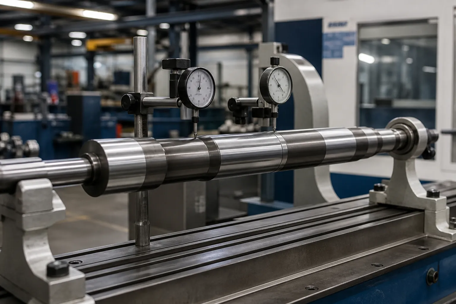
The tolerance zone definition dictates how the part must be measured:
- Surface straightness is checked by running a probe or gauge along individual line elements — each line in the controlled direction must stay within the two-line zone. On cylinders, this means measuring along the surface at defined angular positions.
- Độ thẳng của trục requires reconstructing the center behavior of the feature. In the workshop this is commonly done by rotating the part between centers or knife-edge supports and reading the runout of the surface with a dial indicator or LVDT — accepting that this method actually measures a composite of the axis deviation and local form error of the surface. Multi-point electronic measurement on straightening machines does exactly this: several sensors along the length reconstruct the bend profile while the part rotates. The difference between straightness, runout and TIR — and why they are so often conflated — is covered in detail in Độ thẳng của trục so với Runout so với TIR.
- Support conditions change the result. A slender shaft measured between centers, on two supports, or in a V-block produces different readings, because gravity sag and support reactions deform the part differently in each setup. Dài, flexible parts may even require support-position compensation or measurement under defined restraint. This is not a theoretical nuance; it is the difference between two inspection stations agreeing or not.
- Roundness contaminates the signal. An out-of-round section rotating on supports shows up as runout that has nothing to do with the axis being bent. Separating these effects before making accept/reject decisions is its own discipline — see roundness vs bend in rotating measurement.
Whichever method is chosen, one rule holds: the measurement must resolve what the tolerance zone defines. A single dial indicator reading on one side of the part is not a straightness measurement of a cylindrical zone; it is one projection of a more complex geometry.
Chấp nhận: Turning Measurements into a Decision
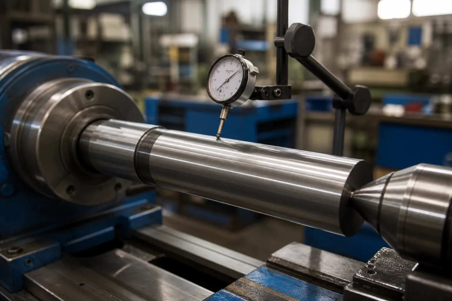
Acceptance is where the drawing, the measurement method and the process meet. A robust straightness acceptance rule answers five questions:
- Which control applies — surface line elements or axis? (Determined by where the frame attaches.)
- Which zone — two parallel lines, or a cylinder with or without MMC bonus?
- Which measuring setup — supports, trung tâm, restraint, and the sensor arrangement that reconstructs the defined quantity. Document it; a straightness number without its setup is meaningless. The trade-offs between contact and non-contact measurement belong in this decision.
- Which measurement uncertainty — the gauge must be several times more accurate than the tolerance it verifies, and for serialized production the measurement system should be validated formally (nhìn thấy máy đo R&R để làm thẳng các đường thẳng).
- Which disposition rule — what happens to a part that measures outside the zone: rework within defined correction limits, or scrap. The interaction between tolerance, correction limit and material behavior is covered in our guide to Giới hạn phân loại và làm lại NOK.
Mature operations write these five answers down per part number. The alternative is each shift improvising one of them — usually the last two.
Common Straightness Specification Mistakes
- Calling runout when straightness is meant. Runout controls a surface relative to a datum axis; axis straightness controls the feature’s own median line. They respond to different geometry errors and cannot be converted into each other without assumptions.
- Over-tightening beyond function. Straightness tolerances tightened “for safety” without a functional driver make parts unmanufacturable or straightening uneconomical. Tolerance should reflect assembly or performance requirements, and MMC should be applied where clearance fit is the functional intent.
- Ignoring support-state effects. Specifying a tolerance that is checked in a different support condition than the part experiences in function or in the machine creates disputes that no amount of measurement resolves.
- Confusing bow with local form. A long gentle bow and short-wave waviness are both “sự thẳng thắn” errors but demand completely different correction and measurement approaches.
Key Takeaways
- Straightness has two distinct meanings in ASME Y14.5 — surface line straightness and axis (derived median line) straightness — distinguished by where the feature control frame attaches. Identify which one applies before anything else.
- Straightness is a form control: no datum reference, and on features of size it interacts with Rule #1 and the diameter measurement.
- MMC on axis straightness enables bonus tolerance and functional gauging; a straightening line should apply the straightness limit as a function of each part’s actual size, not as a fixed number.
- The measurement must resolve the defined tolerance zone: line-by-line for surface control, center reconstruction for axis control — with support conditions and roundness effects accounted for.
- Acceptance is a written rule: điều khiển, zone, cài đặt, gauge capability and disposition. Document all five per part number.
If your drawings specify straightness tolerances that a straightening process has to hold, the measuring strategy should be agreed at the same time as the machine concept — sensor arrangement, support conditions, acceptance rule and disposition logic all determine whether the machine can close the loop. We configure straightening systems against the drawing, not against generic targets, and we are glad to review your callouts and tolerance stack as part of that process.