
I-žarek ali H-žarek ni okrogla palica z večjim premerom. Njegovi dve prirobnici in mreža tvorita odprt del, katerega togost se spreminja glede na smer. Varjenje, rezanje, rokovanje in izdelava lahko povzročita kotno popačenje prirobnice, vzdolžni pregib, stransko pometanje, zasuk ali lokalna deformacija mreže. Vsaka napaka potrebuje drugačen podatek, pot obremenitve in način popravka.
Učinkovit stroj za ravnanje I žarkov mora odgovoriti na pet vprašanj, preden se izbere oprema:
- Ali je obdelovanec valjani profil, varjen vgrajen nosilec, stožčasti žarek, T-prerez ali izdelan sklop s priključki?
- Je kotno popačenje prirobnice nadzorovane napake, pregib, pomesti, zasuk, valovitost spleta ali kombinacija?
- Kje lahko valji, podpira stik z orodjem za stiskanje, ne da bi zdrobil mrežo, označevanje končne površine ali obremenitev občutljivega varjenega območja?
- Ali zahtevani popravek spada v ravnalnik neprekinjenih prirobnic, postajo za tisk, sistem twist/camber ali pot inženirskega pregleda?
- How will the fully released beam be remeasured and accepted under the customer's drawing and applicable fabrication procedure?

*Prikaz inženirskega koncepta varjenega H-nosilca v neprekinjeni celici za ravnanje prirobnic. Ne gre za fotografijo strani stranke ali trditev o učinkovitosti. Pravi valji, vodniki, obseg odseka, sile in sprejemljive meje zahtevajo nadzorovano družino žarkov in reprezentativne preskuse vzorcev.*
Definirajte družino žarkov in fazo proizvodnje
| Družina obdelovancev | Glavna razlika | Zahtevana pot |
|---|---|---|
| Vroče valjani I- ali H-prerez | Geometrija prihaja iz mlina; med ravnanjem ali kasnejšo izdelavo lahko pride do popačenja | Potrdite stanje mlina, lastnosti odseka in dovoljeno hladno korekcijo |
| Varjeni vgrajen H-nosilec | Rebraste in prirobne plošče so spojene z vzdolžnimi zvari; kotna distorzija prirobnice je pogosta napaka po varjenju | Merjenje, specifično za prirobnico, in zvezna ali stopenjska korekcija |
| T-žarek | Ena prirobnica in ena mreža ustvarjata asimetrično pot obremenitve | Namenska podpora in postavitev vodnika |
| Stožčasti ali spremenljivo globok žarek | Globina in togost mreže se po dolžini spreminjata | Recept in položaj orodja morata slediti zemljevidu odseka |
| Asimetrični odsek I/H | Neenake prirobnice ali zamaknjena mreža spremenijo nevtralno os in vzmet | Ločeno preverjanje družine in vzorcev |
| Žarek z ojačitvami, končne plošče ali nosilci | Nastavki prekinejo kontaktna območja in lahko povzročijo popačenje | Ravnanje ob upoštevanju funkcij in lokalni inženirski pregled |
| Pocinkano, pobarvan ali končno prevlečen žarek | Stične sledi in poškodbe prevleke postanejo predmet prevzema | Kvalificirane blazinice/valji in pregled površin po postopku |
| Vgrajen ali med servisiranjem poškodovan strukturni element | Obremenitve, razpoke in zgodovina povezav morda neznana | Gradbeni inženiring in inšpekcijska pot, ni proizvodni recept |
Ta stran se osredotoča na nadzorovano ravnanje valjanih ali varjenih komponent tramov pred končno izdajo. Ne dovoljuje terenskega popravka strukture v uporabi.
Ločite načine popačenja
Kotno popačenje prirobnice
Vzdolžno varjenje lahko obrne ali nagne robove prirobnic glede na mrežo. Namenski ravnalnik prirobnice uporablja nadzorovano obremenitev valja proti prirobnici, medtem ko vodi žarek skozi stroj. Stierli-Bieger opisuje korekcijo hidravličnega valja pri neprekinjenem delovanju za varjene nosilce; Corimpex opisuje horizontalne sisteme, ki popravljajo prirobnice varjenih H-nosilcev kot del varilne linije.
This is not the same as correcting the full beam's longitudinal centerline.
Vzdolžni pregib
Camber is curvature in the beam's strong-axis plane. Lahko je namerno ali nenamerno. Risba mora razlikovati med načrtovanim pregibom in popačenjem, preden se izda kakršen koli ukaz za popravek.
Stranski pomik
Sweep je ukrivljenost v ravnini šibke osi. Potrebuje drugačno podporo in smer obremenitve od pregiba, in razmerje med tanko mrežo/prirobnico lahko naredi odsek občutljiv na lokalno nestabilnost.
Twist
Zasuk je vrtenje odseka vzdolž njegove dolžine. Valjčni prehod samo s prirobnico lahko pusti zasuk nespremenjen ali ga prerazporedi. Twist potrebuje meritve indeksiranih odsekov in nadzorovano torzijsko pot.
Spletna valovitost, Upogib ali lokalna poškodba
Lokalna deformacija mreže ni samodejno vnos ravnalnega stroja. Upogibanje s tanko mrežo, udrtine, razpoke, napake zvara in poškodbe zaradi toplote zahtevajo pregled in inženirsko odpravo pred uporabo sile.
| Opaženi rezultat | Možen vzrok | Pot |
|---|---|---|
| Oba robova prirobnic kažeta dosledno kotno napako po varjenju | Krčenje zvara in rotacija prirobnice | Kandidat za namensko ravnanje valjev za prirobnice |
| Središčna črta žarka se ukrivi navpično, kot preseka pa ostane stabilen | Pregibni ali močni lok | Izmerjena pot stiskanja ali pregiba |
| Žarek zakrivljen vstran | Sweep ali šibko osni lok | Bočna podpora in korekcijska pot |
| Prečni kot se vrti po dolžini | Twist | Merjenje torzije in namenska korekcija zasuka |
| Kratka ostra sprememba v bližini priključka ali zaustavitve zvara | Lokalna omejitev, vnos toplote, poškodbe ali napake pri izdelavi | Pregled in pot do inženiringa; ne povpreči v globalno ukrivljenost |
| Splet prikazuje valove, prirobnice pa ostanejo poravnane | Lokalna nestabilnost mreže ali krčenje zvara | Spletna inženirska pot; ravnalnik prirobnice morda ne bo rešil |
| Izmerjena oblika se spremeni, ko se podporni položaji premaknejo | Povesitev težkega nosilca ali nestabilna referenčna točka | Zamrznite podporne in merilne pogoje, nato ponovite |
Vzpostavite referenčno verigo, specifično za žarek
Dolga težka greda se lahko povesi na tekočih trakovih in lahko drugače sedi na obrabljenih ali neenakih valjih. Inšpekcijski načrt mora opredeliti:
- usmerjenost žarka in osni izvor;
- referenčna prirobnica, spletna sredinska ravnina in končni prerez;
- število podpor, razmik, višina valja in previs;
- ali je rezultat v prostem stanju, nadzorovana podpora ali referenca na vpenjalo;
- pregibni profili po celotni dolžini;
- vrtenje ali zasuk odseka na nadzorovanih aksialnih postajah;
- kot med prirobnico in mrežo na obeh straneh;
- širina prirobnice, debelina, ravnost in stanje robov;
- web globina, debelina, ravnost in lokalna valovitost;
- mesto zvara, stanje konice zvara in izključena merilna območja;
- ponovljivost po raztovarjanju, obračanje ali vrtenje žarka;
- correlation with the customer's fixtures, merila in definicija risbe.

*Ilustracija inženirskega koncepta ločenih meritev celotne dolžine in prereza. Ne gre za predpisano postavitev tirnice. Dejanski položaji senzorjev, izračuni razmika med podporami in prevzema zahtevajo risbo in korelacijo med strankami.*
Zaščitite splet, Zvari in končne površine
Privzeto zaščitena območja ali območja pregleda
- nepodprta tanka spletna območja pod koncentrirano stiskalno obremenitvijo;
- zvar prstov, začetki/ustavitve varjenja in indikacije nepreverjenega varjenja;
- robovi prirobnic, ki določajo končni vmesnik;
- luknje za vijake, reže, prevleke in izrezi;
- ojačitve, oklepaji, končne plošče in priključne podrobnosti;
- identifikacijske oznake in oznake za sledljivost;
- pocinkana, pobarvane ali arhitekturno izpostavljene površine brez kvalificiranih kontaktnih ploščic;
- udrtine, razpoke, laminacije, zareze, močna korozija ali območja prejšnjih popravil.
Potencialno odobrena kontaktna območja
- široka območja prirobnice, ki jih identificira risba kontroliranega preseka;
- ojačane cone za prenos obremenitve v obliki mreže/prirobnice, podprte proti lokalnemu uklonu;
- zamenljivi valjčni profili, ki se ujemajo z geometrijo prirobnice in stojine;
- očistite nepremazane površine pred končno obdelavo, ko to dovoljuje načrt postopka;
- handling points verified for the beam's mass, težišče in postavitev priključkov.
Zemljevid stikov mora biti revizijsko nadzorovan glede na družino razdelkov. Položaj valja, ki ustreza H-nosilki z vzporedno prirobnico, lahko moti zoženo prirobnico, ojačitev ali asimetrični del.
Na zemljevidu napak izberite način popravka
Neprekinjeno ravnanje valjev s prirobnico
Ta metoda je primerna, kadar je nadzorovana težava ponovljivo kotno popačenje prirobnice vzdolž varjeno izdelanega nosilca. Stierli-Bieger opisuje enega ali več prehodov z valji, nameščenimi na obdelovanec, in zahtevano korekcijo. Corimpex opisuje vodoravno napajane sisteme z neodvisno postavljenimi korekcijskimi skupinami. Proizvodno rešitev je treba še opredeliti:
- podprta usmerjenost žarka;
- profili zvitkov in razmiki za vsako prirobnico in obseg trakov;
- vodilni položaji in nadzor proti zvijanju;
- zaporedje prehodov in nastavitev omejenega valja;
- višina vstopnega/izstopnega transporterja in sinhronizacija;
- zvariti, zaščita površine in robov;
- sproščeno preverjanje kota prirobnice in polnega nosilca.
Popravek pritiskanja točke za pregib ali pomik
Hidravlična stiskalnica lahko obravnava izmerjeno globalno ali lokalno napako središčnice, ko podpore in točka stiskanja tvorijo varno pot obremenitve. Zahteva široko orodje, stabilnost žarka, meje sile/premika, krmiljenje vzmeti in popolnoma sproščeno ponovno merjenje. Koncentrirana obremenitev se ne sme postaviti na nepodprto tanko mrežo preprosto zato, ker je to geometrijsko priročno.
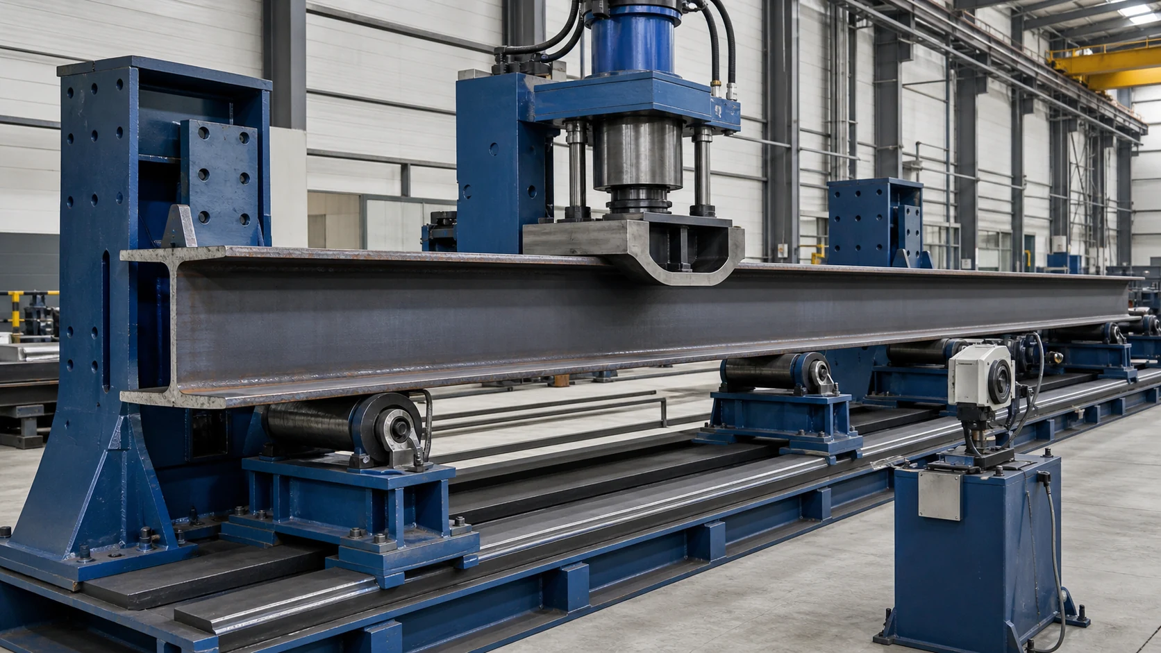
*Ilustracija inženirskega koncepta stiskalnice z dolgim žarkom. Ni univerzalni primer obremenitve. Razpon podpore, orodje, lokalni stres, odpornost proti upogibanju, vzmet in stanje površine zahtevata validacijo vzorca in inženirsko odobritev.*
Popravek zasuka ali več osi
Ko se vrtenje odseka spreminja po dolžini, stroj potrebuje nadzorovane reakcijske točke in uporabo navora. Kot prirobnice, pregib, pometanje in zasuk je treba ponovno preveriti po vsakem popravku, ker lahko ena operacija premakne drugo komponento napake.
Toplotno ravnanje
Toplotno ravnanje je ločen nadzorovan proizvodni proces. Potreben je odobren postopek, pregled materiala in zvarov, nadzor temperature in usposobljeno osebje. Ta stran nenadzorovanega segrevanja gorilnika ne obravnava kot nadomestilo za izmerjen postopek mehanskega ravnanja.
Preberi ravnanje s stiskalnico proti ravnanju z valji za splošno primerjavo metod, nato uporabite zgornje preglede poti obremenitve in nestabilnosti, specifične za žarek.
Integrirajte meritve, Ravnanje in varnost
Zaradi težkih dolgih tramov je ravnanje z materialom del sistema za ravnanje in ne dodatna oprema. Proizvodna celica lahko zahteva:
- pogonski vstopni in izstopni valjčni transporterji;
- sinhroniziran transport skozi korekcijsko cono;
- stranska vodila, ki se stabilizirajo, ne da bi se zaskočila v napačni referenčni točki;
- dviganje, opremo za obračanje ali vrtenje za 180 stopinj, ko obe strani zahtevata dostop;
- nastavljiva višina valja za menjavo odsekov;
- zaznavanje končne in stranske prisotnosti;
- varna območja okoli premikajočih se koncev žarkov in točk stiskanja;
- receptne zapore za družino odsekov in orientacijo;
- sledljivost dohodnih, vmesne in izdane meritve.
Bendmak javno pozicionira ravnanje H-profila pred ali po izdelavi, ko so prirobnice ali trakovi ukrivljeni. Corimpex združuje horizontalni ravnalnik žarkov z varjenjem, oprema za montažo in vrtenje žarka. Ti tržni primeri podpirajo integrirano linijsko arhitekturo; ne določajo zmogljivosti ali natančnosti predlagane celice StraighteningTech.
Zgradite inšpekcijska vrata okoli ravnanja
Pred popravkom, potrdite:
- oznaka odseka, potrdilo o materialu in zgodovino toplote ali izdelave;
- revizija risbe in namerno pregib ali zožitev;
- stanje zvara in razporeditev zahtevanega vizualnega ali neporušitvenega pregleda;
- priloga, zemljevid lukenj in izrezov;
- stanje površine/prevleke in dovoljena kontaktna območja;
- vhodni kot prirobnice, pregib, pomesti, zasuk in zemljevid lokalnih napak;
- upravičenost do popravka in pogoji za zavrnitev/inženirski pregled.
Po popravku, ponovite nadzorovano dimenzijsko kontrolo in vse zahtevane preglede zvarov ali površin. Z ravnanjem ne morete popraviti razpoke, nesprejemljiv zvar, laminacija, raztrgana luknja, huda lokalna sponka ali izgubljeni odsek.
The governing tolerance should come from the customer's drawing and applicable fabrication or product standard. Do not copy a machine supplier's sample range into a project acceptance specification.
Demonstracija ravnanja zunanjega H-žarka
Naslednji zunanji video prikazuje stroj za ravnanje prirobnic H-nosilcev. Vključen je za ponazoritev kategorije opreme, ne kot primer stranke StraighteningTech, specifikacijo stroja ali dokazilo o prevzemu.
Informacije, potrebne za tehnični predlog
| Vnos | Najmanjše podrobnosti |
|---|---|
| Družina Beam | Valjani ali varjeni; jaz, H, T, zožene, asimetrična ali izdelana montaža |
| Razpon odseka | Celotna dolžina, širina/debelina prirobnice, višina/debelina in masa mreže |
| Material in oder | Ocena, toplotno stanje, postopek varjenja, pred/po izdelavi in stanju premaza |
| Načini napak | Kot prirobnice, pregib, pomesti, zasuk, spletna valovitost in zemljevid lokalnih napak |
| Zahtevani rezultat | Toleranca risanja, datum, stanje podpore, postaje in način pregleda |
| Zaščitene funkcije | Zvari, luknje, spopada, ojačitve, končne plošče, premazi in končni vmesniki |
| Ravnanje | Način nalaganja, orientacija, težišče, višina transportnega traku in zahteva za obračanje |
| Potreba po proizvodnji | Mešanica izdelkov, premagati tarčo, menjava, avtomatizacija in sledljivost |
| Načrt kakovosti | Stanje varjenja/NDT, površinski pregled, merilna korelacija, FAT/SAT in oblika poročila |
Če je vnos nepopoln, prvi rezultat bi moral biti meritev in načrt vzorčenja, ne pa izmišljena sila, natančnost ali vrednost prepustnosti.
Od preizkusa vzorca do proizvodnje
- Pregled risb, družine oddelkov, varilnih postopkov in prevzemnih dokumentov.
- Ločen kot prirobnice, pregib, pomesti, zasuk in lokalna poškodba.
- Zamrzni podporo, datum in merilna metoda.
- Določite zaščitena in dovoljena kontaktna območja.
- Izmerite reprezentativne običajne vzorce in vzorce v najslabšem primeru.
- Preizkusite izbrani valj, pritisnite ali večosno korekcijsko pot.
- kvantificirati vzmetni povratek, navzkrižna sklopka, površinsko označevanje in ponovljivost.
- Ponovno preglejte zvare in površine v skladu z načrtom kakovosti.
- Correlate released results with the customer's gauges.
- Orodje za zamrzovanje, recepti, meje ustavitve, obdelava logike in polj sledljivosti.
- Teči preizkus vzorca in prevzem pred izdajo potrjene družine.
For an I-beam and H-beam application like this one, procurement teams usually pair the potek izbire ravnalnika with the proračunska slika za ravnalni stroj before shortlisting vendors.
Pošljite nam svoje risbe tramov, obseg odseka, zemljevid izkrivljanja in metoda sprejemanja da prejmete koncept ravnanja in upravljanja. StraighteningTech razvija opremo, orodje, potek dela meritev in preverjanja okoli dejanske družine žarkov namesto uporabe ene splošne nastavitve za vsak profil.