
Вращающийся индикаторный след может содержать сразу несколько эффектов.. Это может отражать ось заготовки, локальная округлость, цилиндрическая форма, базовое отношение, поддержка сидений, ошибка приспособления, настройка датчика или прерванная функция. Называя каждое высокое показание «изгибом», можно привести к неправильному корректирующему действию и повредить деталь, которая действительно требует измерения или проверки обработки..
В этом руководстве объясняется, как диагностировать сигнал перед принятием решения о выпрямлении.. Он не устанавливает систему измерения StraighteningTech., терпимость, разрешение сенсора, процедура определения исходных данных или возможность коррекции. Для принятия окончательных решений необходимы контролируемый чертеж и метод проверки заказчиком..

*Иллюстрация инженерной концепции. Это показывает, что вращающийся сигнал может включать в себя изменение формы.; это не результат измерения детали заказчика или предписанной установки проверки.*
Назовите характеристику, прежде чем читать показания датчика
Округлость описывает состояние формы поперечного сечения.. Изгиб оси описывает пространственный путь базовой оси.. Биение — это измерение с вращением относительно базовой точки, на которое могут влиять несколько факторов.. Соосность, концентричность и цилиндричность также имеют отдельные определения и требования к проверке.. На чертеже должно быть указано, какая характеристика контролирует приемку..
| Сигнал или характеристика | Диагностический вопрос |
|---|---|
| Округлость / лобовой | Изменяется ли местный радиус при вращении сечения?? |
| Изгиб оси | Меняет ли положение опорной оси по длине? |
| Закончиться | Какая база данных, опоры и зондовая станция создают показания? |
| Коаксиальные отношения | Сравниваются ли несколько объектов с определенной общей осью?? |
| Сигнал прибора | Изменяет ли переустановка или изменение ориентации опоры результат?? |
Видеть прямолинейность вала, биение и МДП и соосность и биение по соответствующей терминологии.
What a Rotating Trace Is Made Of
A probe reading taken while a part rotates is, mathematically, a mix of components that repeat once, twice, three times and more per revolution. Reading the mix is the core diagnostic skill. A once-per-rev component means the surface is, on average, further from the rotation axis on one side than the other — which is the signature of either an axis offset between the part’s reference geometry and the rotation axis, or of a bent axis displacing the section as a whole. A twice- or three-times-per-rev component means the section is oval or lobed: the local radius itself changes around the circumference, a form condition of the cross-section that no amount of axis correction removes. Higher-frequency content usually reflects surface texture, keyways and interrupted features, or vibration entering through the supports.
The decisive separation between the two once-per-rev causes is axial. A true bend displaces different stations by different amounts and often in different directions, so the once-per-rev component’s amplitude and phase change as the probe moves along the part. A pure eccentricity condition — centers offset, seat offset, chuck runout — produces a once-per-rev component that keeps the same phase and proportional amplitude at every station. One trace at one station cannot distinguish them; a short axial map routinely can. That is the reasoning behind the multi-station discipline above, and behind multipoint measurement arrangements that read several stations in one setup.
Where Lobing Comes From
Lobing is rarely random — it carries the fingerprint of the machining that produced the surface, which is what makes it diagnostic. Three-lobe out-of-roundness is the classic signature of parts ground on centerless machines, where the part floats between wheel, regulating wheel and blade and the geometry locks into a three-point stability condition. Even-lobe ovality traces back to opposing clamping or distortion relieved after machining — a thin sleeve released from a chuck, a part that relaxed after heat treatment. Odd lobing beyond three appears with certain workholding arrangements and with relapsing of interrupted cuts. Knowing the part’s process route therefore tells you what lobing to expect and whether an observed lobe count is a workpiece reality or an artifact of the current setup: a lobe count that changes when the part is reseated in different orientations is being generated by the setup, not the part.
Сначала проверьте базу данных и настройку
Прежде чем интерпретировать часть, проверьте возможности центра, журналы или другие справочные поверхности, условие поддержки, чистота, контакт зонда, метод вращения и осевая станция. Поврежденный центр, картавить, грязное сиденье, неправильный контакт опоры или зонда на прерывистой поверхности может привести к кажущемуся биению, которое не отражает изгиб оси.
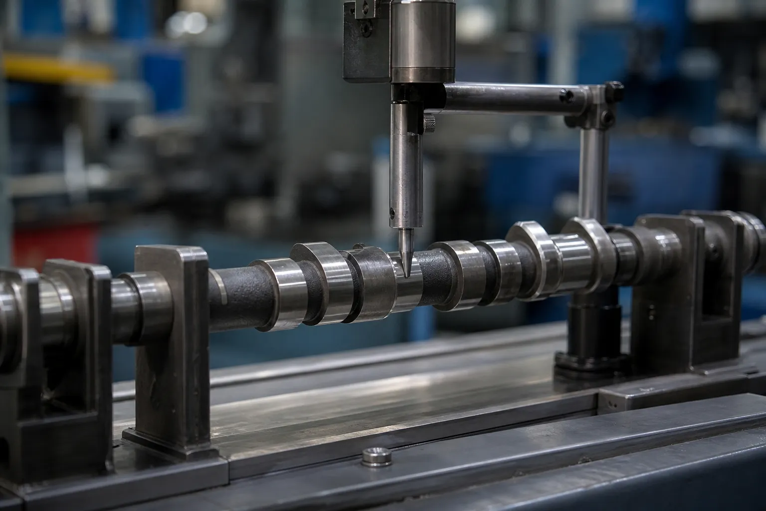
*Иллюстрация инженерной концепции. Он иллюстрирует функциональное измерение журнала.; фактические данные, Дорожки щупа и угловые маски зависят от контролируемой детали.*
Используйте проверку переустановки/повтора и сравните несколько станций.. Если трассировка существенно изменится после повторения настройки, исследуйте реализацию приспособления или базовой точки перед применением корректирующей силы.
Сравните несколько станций и ориентаций
Для изгиба оси обычно требуется карта осей.. Локальная округлость или лопастность могут появиться на одной станции, но не на другой.. Одно общее значение индикатора в одной точке не может доказать, какой вкладчик доминирует.. Запись местоположения станций, ориентация, исходное состояние и трассировка или расчетный результат, требуемые процедурой приемки.
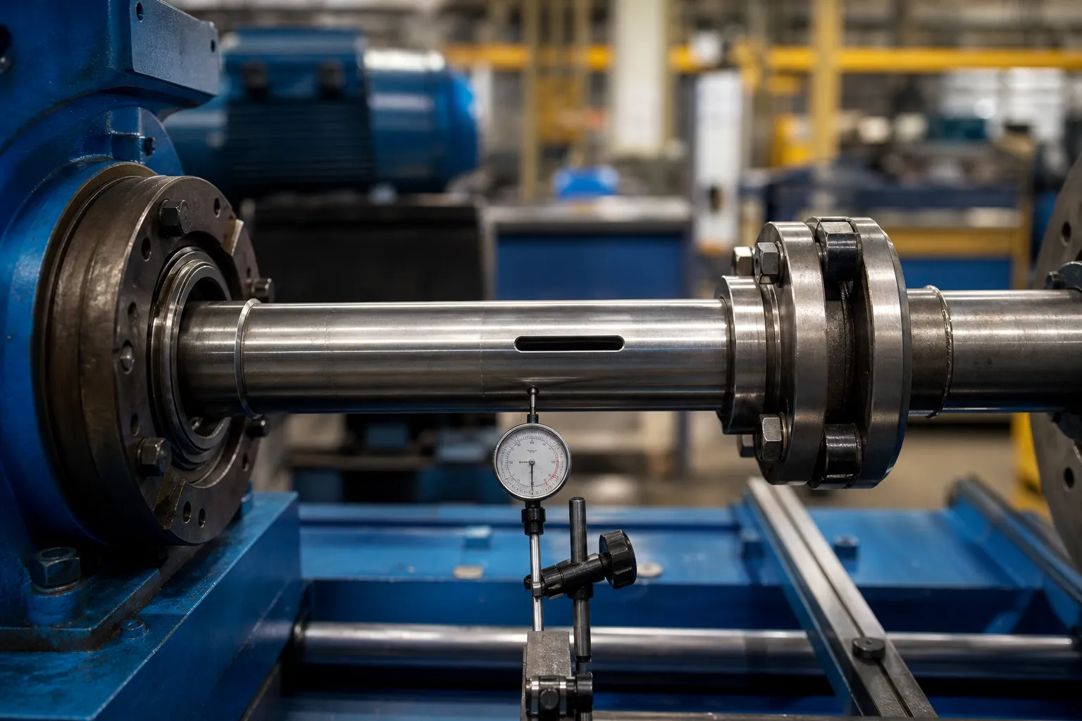
*Иллюстрация инженерной концепции. Он представляет собой многофункциональный вопрос измерения вращения., не одобренное приспособление или вывод о том, что наблюдаемый сигнал является искривленным.*
Separating Spindle Error From Part Error
On any rotating instrument, the reading contains the part’s geometry plus the rotation error of the instrument itself — spindle runout, bearing wander, support eccentricity. Precision metrology has standard separation techniques for this, and their logic is worth knowing even when the full apparatus is not available. Reversal methods measure the part in one orientation, then rotate the part exactly half a revolution relative to the fixture and measure again: part error keeps its sign in part coordinates while setup error keeps its sign in machine coordinates, so combining the two traces separates them. Multistep methods extend the same idea through a series of indexed orientations. On a production straightening machine, the practical descendants are simpler: reseating the part in a different clocking orientation and checking whether the trace rotates with the part or stays fixed in the machine tells most of the story, and comparing readings before and after swapping a support identifies which element contributes what.
These checks cost minutes and prevent the most expensive mistake on this page: correcting a bend that lives in the bench. They also make the eventual correlation to the customer gauge meaningful, because both sides of that comparison are then measuring parts rather than setups — the premise underlying калибр R&R studies on straightening lines.
A Practical Diagnostic Sequence
The checks above assemble into a fixed order of operations that experienced lines follow before any correction decision. Первый, clean and inspect the seating features — centers, журналы, support vee blocks — for damage, burrs and debris, since the cheapest explanation is always the setup. Второй, take a trace, reseat the part in the same orientation, and retrace: disagreement beyond the setup’s established repeatability stops the investigation at the fixture. Third, reseat in a rotated orientation: a trace that follows the part is a part signal; one that stays fixed in the machine is a machine or fixture signal. Fourth, map at least three stations along the length and note how the once-per-rev component’s amplitude and phase behave: varying amplitude and rotating phase indicate bend; constant phase with proportional amplitude indicates eccentricity. Fifth, look at the lobe content in relation to the part’s machining history before believing any form conclusion. Only then choose the response — correction for confirmed axis bend within approved zones, or the alternative routes for everything else, with the released-state condition treated per измерение загруженности и отпускания.
The sequence exists because each step filters a class of false positives that would otherwise survive to the next. Skipping ahead to correction is how parts get pressed for eccentricity fixtures, ovality and chucking artifacts — damage that no later measurement undoes.
Выберите ответ из диагноза
Если доказательства подтверждают состояние изгиба оси и существуют утвержденные зоны контакта/опоры., потенциальный маршрут выпрямления может быть оценен с помощью выборочного испытания. Если сигнал в основном имеет округлость, прерванная геометрия, проблема с данными, ошибка крепления или отношение отдельного элемента, может потребоваться другой процесс или инспекционная проверка. Не используйте выпрямление для компенсации проблем с измерением..
Для контролируемой локальной коррекции, видеть точечное выпрямление. Для корреляции с методом окончательного контроля, see machine gauge versus customer gauge correlation.
Подтвердите с помощью шкалы клиента
План отбора проб должен включать известные/эталонные условия, если таковые имеются., повторить настройку, несколько станций, измерение в выпущенном состоянии, идентификация деталей и приспособлений, сохранение необработанных данных и корреляция с показателями клиентов. В результате должно быть указано, какая характеристика была оценена и какая неопределенность или ограничения настройки остаются..
Часто задаваемые вопросы
Всегда ли высокий TIR означает, что вал погнут??
Нет. МДП может включать датум, округлость, приспособление и другие участники. Сначала проведите диагностику установки и нескольких станций..
Можно ли выпрямить правильную округлость?
Не как общий вывод. Округлость — это другое геометрическое состояние, которое может потребовать другого процесса или маршрута проверки..
Зачем повторять настройку?
Повторное считывание после переустановки помогает отличить сигнал заготовки от опоры., изменение исходной точки или приспособления.
What does a three-lobed trace usually indicate?
Most often, a surface produced by centerless grinding, where the three-point contact of wheel, regulating wheel and blade locks the section into a three-lobe form condition. It is a cross-sectional form issue, not an axis issue, and it should be verified against the part’s machining history before any response is chosen.
How can I tell eccentricity from bend with one probe?
Move the probe along the part and watch the once-per-rev component. Bend shows varying amplitude and shifting phase between stations; eccentricity keeps the same phase and proportional amplitude everywhere. If the probe cannot move, mapping several stations with a moved setup achieves the same separation at the cost of reseating discipline.
Does reseating the part in a different orientation really separate machine error?
Да, in its simplest form. Part error rotates with the part; machine and fixture error stay fixed in machine coordinates. Comparing traces at two clockings shows which class dominates the reading. Formal reversal and multistep methods refine the same principle when numbers, not just classification, are required.