
Множественные показания смещения могут превратить проверку длинного вала из одного пика в карту ошибок.. Это значение зависит не только от датчика: поддержка геометрии, базовое посадочное место, контакт зонда, ротация/индексация, синхронизация, условия окружающей среды и правила расчета влияют на то, что сообщается.

*Иллюстрация инженерной концепции. Это не спецификация датчика., установленная система или проверенный результат измерения.*
Определите характеристику перед выбором датчиков
Сначала укажите, является ли приемочная характеристика прямолинейностью центральной линии., местный лук, биение относительно базовой точки, отклонение профиля или другой контролируемый результат. След напряжения или смещения датчика сам по себе не является требованием заказчика.. В плане проверки должны быть указаны исходные характеристики., поддерживает, станции, ориентации, охватывать, расчет, единицы, пределы и состояние, в котором деталь принята.
| Элемент | Вопрос на закрытие |
|---|---|
| Датам | Какие элементы определяют опорную ось или поверхность?? |
| Поддерживать | Воспроизводит ли оно состояние клиента или выпущенной детали?? |
| Путь зонда | Являются ли точки контакта функциональными поверхностями и защищены ли они от повреждений?? |
| Станции | Фиксируют ли они известные зоны изгиба и переходы элементов?? |
| Ротация/индексация | Как сохраняется ориентация между чтениями? |
| Расчет | Как показания преобразуются в контролируемую характеристику? |
Для контроля исходных данных, видеть очистка центрального отверстия вала и подготовка исходной точки и повторяемость приспособления и посадка исходной точки.
How an LVDT Works, and Why Its Physics Matters
The linear variable differential transformer earns its place on production machinery through a short list of physical virtues. Inside the housing, a primary coil is excited with an alternating current, and two secondary coils sit either side of it; a ferromagnetic core, attached to the probe tip by a slim push rod, slides along the axis. With the core centered, the induced voltages in the two secondaries balance; displace the core and the balance tips in proportion to the movement. The electronics read the amplitude and phase of that imbalance and report displacement. Because the core never touches the coils, there is no friction or wear inside the sensor; because the coupling is inductive, the reading is largely indifferent to dust, oil mist and humidity that blind optical sensors; and because the moving mass is small, the tip can follow moderate surface motion faithfully. The trade-offs are equally physical: it needs signal conditioning and calibration against a reference, the raw output is relative rather than absolute, and the probe tip itself is a mechanical component with its own condition, force and wear story.
Where Errors Enter Between Probe and Number
Treating the chain as one system, as the section above demands, means knowing the specific doors through which error walks in. Thermal drift: the sensor body, the fixture and the part all expand and contract with temperature, and on a machine that warms through a shift, a morning zero and an afternoon reading are not the same event — hence reference checks on a master at intervals the procedure defines. Mounting: a probe on a long, unsupported bracket is a cantilever with its own compliance, and vibration or cable pull moves the whole assembly relative to the part, indistinguishable from part movement in the data. Dynamics: when the part or probe moves during scanning, the stylus mass and tip force set a speed limit beyond which the tip skips or lags, writing false features into the trace. Contact condition: tip wear flattens the intended radius and changes where the reading sits on a curved surface. None of these is exotic; each is controlled by written procedure — zero method, master check interval, scan speed, tip inspection — which is precisely what the validation framework above asks the system description to contain.
Рассматривайте цепочку измерений как единую систему
LVDT может подойти для относительного смещения., но результат измерения также включает установку датчика, отклонение приспособления, формирование сигнала, время, части посадки и поведение оператора или автоматизации. Записывайте каждый элемент в цепочке, чтобы можно было изучить дальнейшее изменение результата..
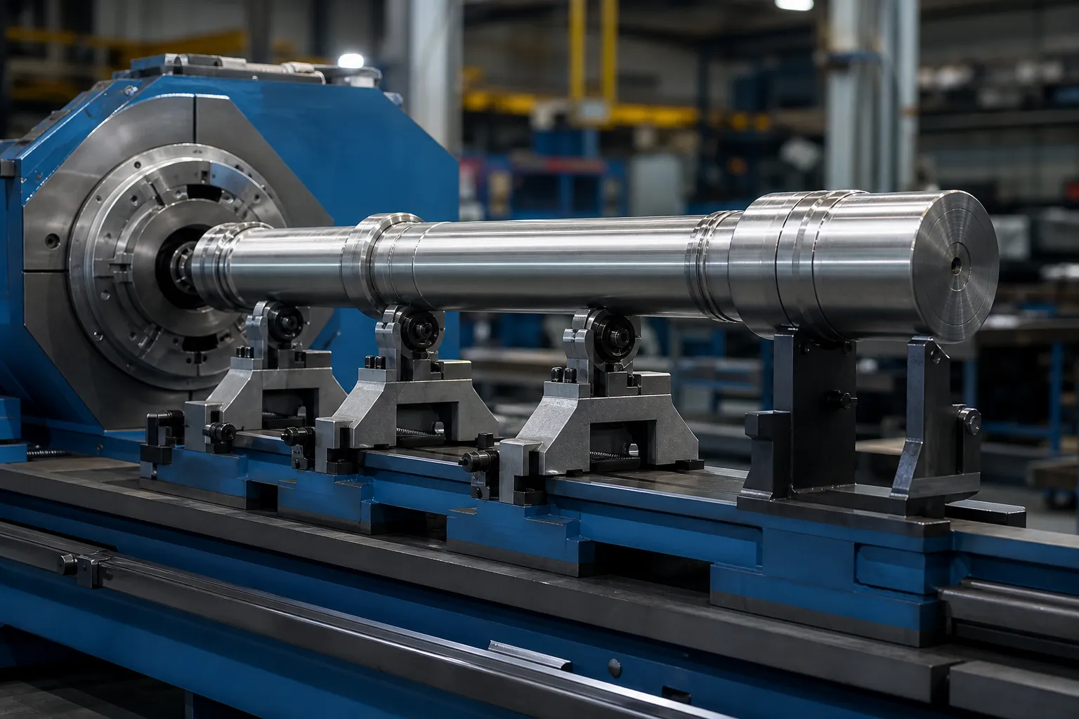
*Иллюстрация инженерной концепции. Жесткость крепления, положение датчика и защита требуют специального проектирования.*
Контролируемая процедура должна охватывать идентификацию датчиков., справочная/основная проверка, состояние монтажа, защита кабеля, нулевой метод, ориентация образца, поддерживать чистоту, настройки сбора и хранения данных. Повторное считывание нестабильного прибора не является свидетельством повторяемости..
Синхронизировать местоположение, Ориентация и чтение
Многоточечные данные полезны только тогда, когда каждое значение может быть присвоено известному положению и условию.. Если деталь вращается или перемещается, определить кодировщик/индекс, координата станции, направление движения, условие пребывания или отбора проб, и что произойдет, если сигнал пропадет. Результат должен сохранить необработанные или отслеживаемые исходные данные, необходимые для восстановления карты..
Избегайте интерпретации локализованного пика без проверки посадки и контакта.. Сброс тестов, обратная ориентация, где это необходимо, и повторное считывание базовой линии могут отличить особенность детали от ложного указания..
Choosing Station Count and Placement
How many stations, and where, is a geometry question before it is a budget question. The error modes of slender parts are smooth in space: a bend is a low-frequency curve, so a modest number of stations — placed where the physics says the information lives — reconstructs it well, while doubling the count in uninformative positions buys data volume, not accuracy. Informative positions are predictable: mid-span between supports where a bow reaches its excursion; each stiffness transition on stepped parts, where peaks like to hide; immediately beside functional features whose relationship to the datum matters; and the free ends, which anchor the map. The failure mode of sparse placement is aliasing in its practical form — a short kink sitting between two stations contributes to neither reading cleanly, and a correction aimed at the reconstructed map presses in the wrong place. The honest way to close this risk is not infinite density but a validation: map a set of parts at high density once, confirm that the production station set reconstructs the same peaks and amplitudes, and document that comparison as the station-plan justification.
Turning the Map Into a Correction Decision
The map exists to drive action, and its action vocabulary has three entries: where to press, in which direction, and how hard to expect the part to respond. Peak position and direction come from comparing stations around the maximum; on a part rotating between stations, preserving angular indexing — the synchronization discipline above — is what converts separate readings into a vector, not a pile of magnitudes. Expected response comes from the stiffness story the map already tells: a peak on a heavy section needs a different correction plan than the same amplitude on a thin one, and peaks at stiffness transitions deserve the respect described for separating bend from roundness and setup effects before any press follows. What the map must not do is trigger correction on unverified signals: a localized reading that has not survived a reseat check is a hypothesis, not a peak. That guard rail — map, проверять, then correct, with released-state measurement closing the loop — is the same sequence that makes автоматическое выпрямление вала converge in few strokes instead of many.
Корреляция с приемкой выпущенной детали
Измерения во время зажима или коррекции могут быть полезны для управления процессом., но это не доказывает автоматически, что выпущенный вал соответствует требованию. Сравните линейный метод с утвержденным методом выпущенных частей на репрезентативных образцах с нормальными отклонениями.. Видеть измерение прямолинейности при нагрузке и отпускании за границу.
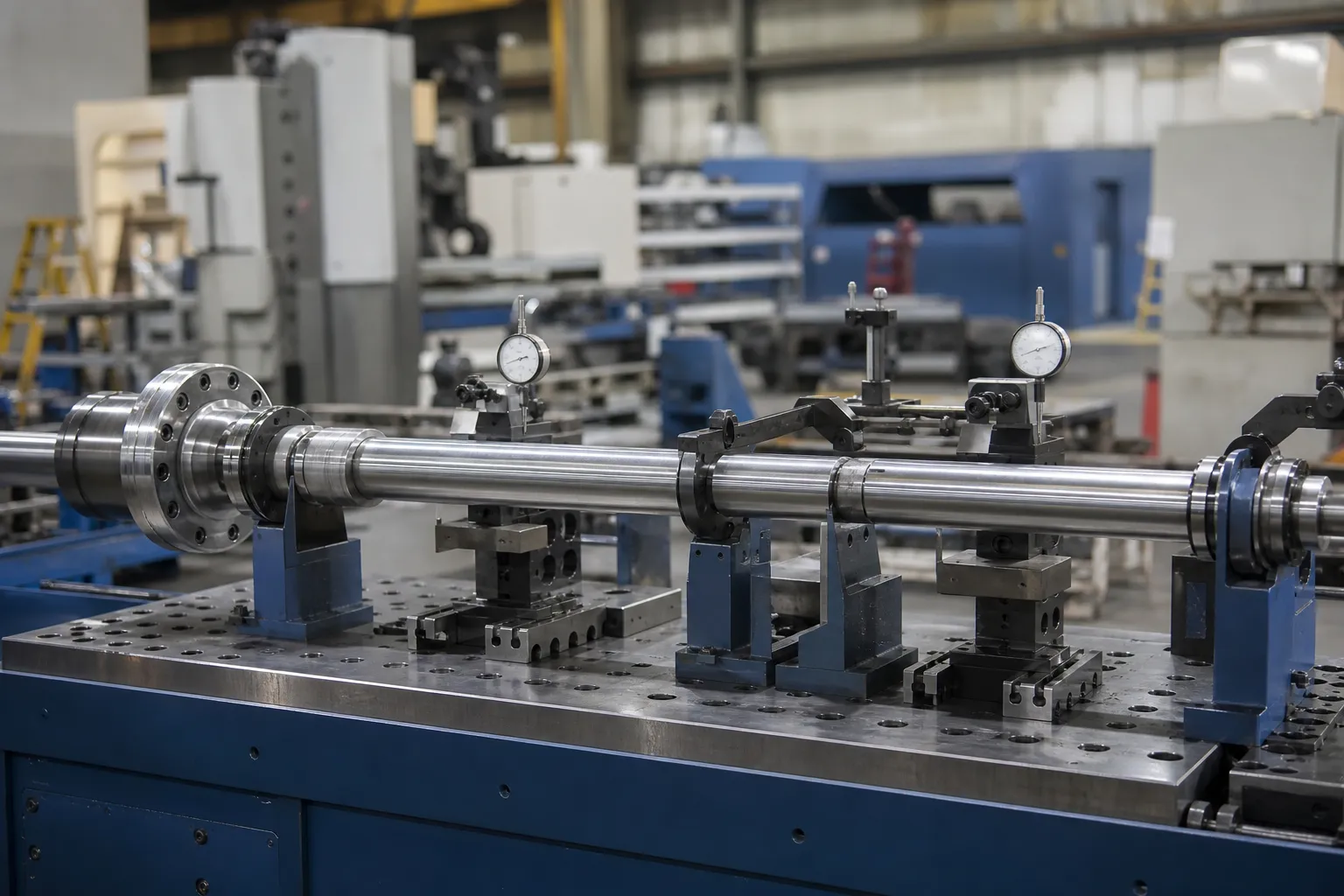
*Иллюстрация инженерной концепции. Эталонный метод, расчет опор и приемка должны контролироваться утвержденным планом качества.*
План корреляции должен определять совпадающие выборки., слепое сравнение, где это возможно, Эквивалентность исходных/опорных данных, статус калибровки, обзор предвзятости, проверка повторяемости/воспроизводимости, разрешенная разница, правила эскалации и контроля изменений. Обратитесь к Корреляция размеров машины и размеров клиента и калибр R&R для выпрямления линий.
Входные данные, необходимые для исследования измерений
Предоставьте чертеж и определение характеристик., существующий метод проверки, геометрия детали и базовые элементы, material/manufacturing stage, expected bend locations, выборочная совокупность, environmental constraints, desired data record and customer acceptance method. Используйте Руководство по испытаниям и приемке образцов для выпрямления to establish the trial record, затем свяжитесь с StraighteningTech для обсуждения заявки.
Требуемая проверка перед подачей претензии на систему
Any multi-point measurement claim needs a defined probe and datum setup, калиброванные эталоны, repeated or reseated readings on representative parts, and customer-gauge correlation. A generic machine capability is not a verified result.
Часто задаваемые вопросы
Does adding more measurement stations automatically improve accuracy?
Нет. Stations placed where the geometry has information — mid-span peaks, stiffness transitions, functional features, ends — improve the map. Stations added elsewhere add data volume and cost while leaving reconstruction essentially unchanged. Validate the chosen set once against a dense map and document the comparison.
Why do LVDT readings drift over a production shift?
Most often thermal: датчик, fixture and part expand at different rates as the cell warms, shifting the zero. Mechanical causes come next — bracket compliance, cable pull, tip wear. The control is procedural: a defined zero method and reference-master checks at set intervals, with any shift beyond the procedure’s limit triggering investigation rather than quiet re-zeroing.
Can multipoint LVDT data replace final inspection?
Only through correlation. In-process multipoint data drives the correction loop; the acceptance decision belongs to the released-state method the customer recognizes. When the two have a documented correlation on representative parts, the line method gains standing — until then it is process control, not release.
Сопутствующие ресурсы по технологиям выпрямления
Видеть как работает автоматическая правка валов, выпрямление образца, испытание и приемка и прямолинейность вала, биение и TIR для общих границ контроля, которые применяются до какого-либо заявления о возможности Многоточечное измерение вала LVDT.
Multipoint measurement pays off at acceptance time – pair the Контрольный список FAT with the ГД&T straightness acceptance guide to agree measurement method and tolerance interpretation in one pass.