
Ротор электродвигателя — это не просто вал двигателя с дополнительной массой.. Однажды ламинированное ядро, клетка для белки, коммутатор, держатель магнита или другой пакет ротора установлен на валу, заготовка имеет новые функциональные поверхности, хрупкие регионы, термическая история и поведение дисбаланса. Прессование, термоусадочный фитинг, литье под давлением, сварка, пайка, термическая обработка и окончательная механическая обработка могут изменить соотношение между двумя шейками подшипника и корпусом ротора..
Поэтому надежное решение для выпрямления ротора электродвигателя должно контролировать состояние всей сборки.: ось подшипника, биение сердечника ротора, открытая геометрия вала, защищенные бесконтактные зоны, пружинение, выпущенное измерение и последовательность между выпрямлениями, закончить точение и балансировку.
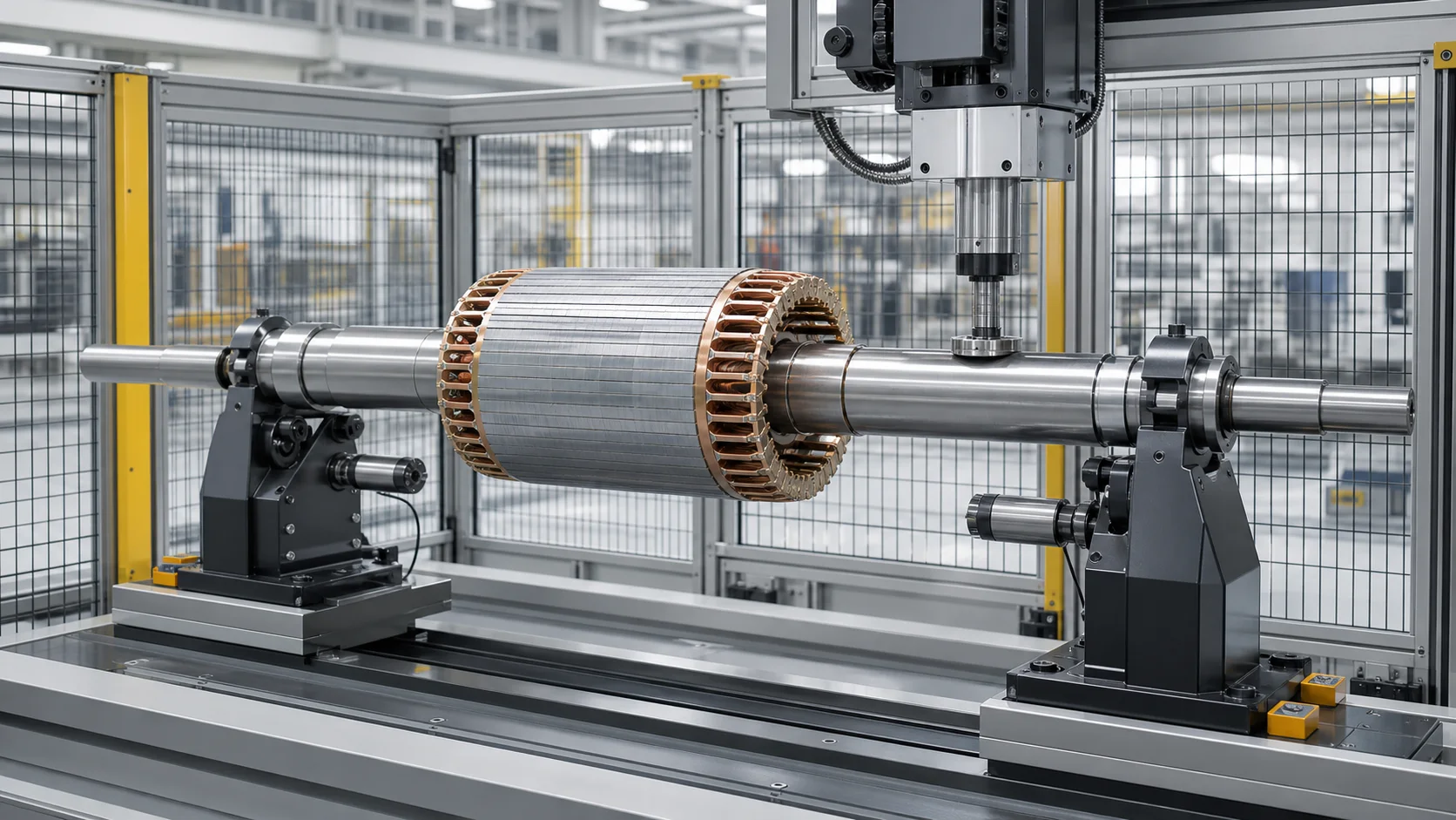
Это иллюстрация инженерной концепции, это не фотография с сайта клиента. Фактическая конструкция ротора, оснастка, план свиданий, Корректирующая сила и уровень автоматизации требуют чертежей и репрезентативных выборочных испытаний..
Полный ротор против голого вала двигателя
Первое решение проекта заключается в том, является ли целью вал или ротор в сборе..
| Состояние заготовки | Основной вопрос по геометрии | Специализированный процесс |
|---|---|---|
| Голый вал двигателя | Приемлема ли ось вала до сборки ротора?? | Центры, седла подшипников, сплайн/резьба/шпоночная канавка и искажение при термообработке |
| Вал с роторным пакетом | Выровнены ли обе шейки подшипника после сборки сердечника/сепаратора/магнита?? | Защита ротора, добавленная жесткость, последовательность изгиба и баланса, вызванная сборкой |
| Ротор после завершения вращения | Соответствуют ли шейки и наружный диаметр ротора в конечном исходном состоянии?? | Защита готовой поверхности и минимальная допустимая коррекция |
| Полный двигатель | Выдерживает ли собранный двигатель вибрацию?, шум, Требования к току и температуре? | Тест системы; не приемка правильной машины сама по себе |
Существующие требования к голому валу относятся к Решение для автоматического выпрямления вала двигателя. На этой странице представлен собранный ротор или якорь перед установкой в статор и корпус двигателя..
Определите семейство роторов
Словосочетание «ротор двигателя» охватывает очень разные детали.. В предложении следует указать:
- асинхронный ротор с короткозамкнутым ротором с литыми или готовыми концевыми кольцами;
- фазный ротор или электрический якорь;
- ротор с постоянными магнитами или синхронный ротор;
- ротор тягового двигателя;
- ротор генератора;
- ротор с коммутатором, контактные кольца, вентилятор, дорожка энкодера или функция соединения;
- сплошной вал, полый вал или охлаждающий канал;
- один кусочек, прессованный, термоусадочный, сварной или собранный другим способом роторный пакет;
- мягко обработанный, термообработанный, финиш, покрытое или сбалансированное состояние;
- ротор с открытыми корректирующими интервалами по сравнению с конструкцией без безопасной открытой зоны вала.
Не каждый ротор можно выправить давлением после сборки.. Постоянные магниты, стопорные втулки, обмотки, изоляция, паяные соединения и интерфейсы с высоким уровнем помех могут создавать строгую силу, пределы температуры и магнитной обработки. Технико-экономическое обоснование должно быть подтверждено для фактического строительства..
Заморозить этап производства
Вал перед сборкой ротора
Это голый проект. Доступ к исправлению обычно лучше, но он не может устранить искажения, возникшие в результате более поздней посадки с натягом., процесс сжатия, литье под давлением или сборка роторного пакета.
После сборки роторного пакета, Прежде чем закончить поворот
Полный эффект сборки присутствует, во время обработки припуск может оставаться на шейках или внешнем диаметре ротора. Галдабини описывает выпрямление ротора как способ улучшить геометрию посадочного места подшипника перед обточкой и уменьшить ненужный съем припуска.. Это принцип планирования процесса., не универсальная гарантия экономии материала.
После завершения точения или шлифования
Подшипниковые шейки, плечи и поверхность ротора обработаны. Пределы контакта инструмента и вмятин становятся критически важными, и для коррекции можно использовать только утвержденные открытые пролеты валов..
После балансировки
Выпрямление может изменить ось ротора., массовое распределение относительно журналов и ранее измеренный дисбаланс. Ротор, исправленный после балансировки, должен вернуться на заданный маршрут проверки баланса..
| Этап | Преимущество | Основной риск | Требуется перепроверка |
|---|---|---|---|
| Голый вал | Максимальный доступ к коррекции | Более поздняя сборка ротора может снова привести к изгибу. | Повторное измерение после сборки |
| Ротор в сборе, запас остается | Виден изгиб, вызванный сборкой | Пакет ротора и его конечные элементы должны быть защищены. | Корреляция чистовой обработки |
| Обработанный ротор | Функциональные данные доступны | Повреждения поверхности и ограниченные зоны безопасного прессования | Полная проверка геометрии и поверхности |
| Ранее сбалансированный ротор | Доступны существующие данные баланса | Выпрямление может сделать его недействительным. | Окончательная проверка баланса |
Определите, что контролирует чертеж
«Биение ротора» не следует рассматривать как одно неделимое значение.. Соответствующие характеристики могут включать в себя:
- радиальное биение каждой шейки подшипника;
- соосное взаимодействие между двумя осями подшипников и шеек;
- биение удлинителей вала, запечатать следы, соединительные седла или направляющие энкодера;
- биение наружного диаметра сердечника ротора относительно оси подшипника;
- биение коллектора или контактного кольца;
- биение плеча и лица;
- прямолинейность открытого пролета вала;
- округлость и цилиндричность каждой шейки;
- осевое положение роторного пакета, состояние стопки и целостность концевого кольца;
- статический и парный дисбаланс в определенных плоскостях коррекции;
- готовая вибрация двигателя, шумовые и электрические характеристики.
Используйте Прямолинейность вала, биение и направляющая TIR отделить форму, производная ось и индикация вращения. Выпрямление может изменить взаимоотношения глобальных осей.; он не корректирует автоматически округлость журнала, геометрия роторной батареи, электрические дефекты или дисбаланс массы.
Установите функциональные данные
Для большинства собранных роторов, две опорные шейки расположены по центру установленной оси вращения. Направляющие подшипников электродвигателей SKF рассматривают гнезда подшипников вала и заплечики упоров как контролируемые геометрические элементы и явно учитывают радиальное и осевое биение.. Проект по-прежнему должен соответствовать чертежу заказчика и выбранной системе подшипников..
Решение должно отличать:
- чертежные точки отсчета и функциональная ось подшипника;
- производственные центры, используемые для точения или шлифования;
- опоры и устройства вращения для правильных машин;
- датчиковые дорожки, используемые для восстановления биения цапфы и корпуса ротора;
- Опоры балансировочных станков и плоскости коррекции;
- окончательная сборка двигателя и ссылки на испытания.
Центры могут быть полезны для обработки, но ось, определяемая центром, не является автоматически такой же, как ось, установленная готовыми шейками подшипника.. Так же, повторная поддержка ротора не доказывает, что опоры воспроизводят состояние подшипника заказчика.

На этой иллюстрации инженерной концепции показаны несколько дорожек измерения.. Он не предписывает контактные датчики на пакете роторов или одно универсальное опорное устройство..
| Измерительный трек | Основной выход | Риск интерпретации |
|---|---|---|
| Подшипниковые шейки | Функциональная ось вращения и биение шейки | Локальная округлость, загрязнение или сила зонда могут исказить результат |
| Удлинители вала | Изгиб подшипников снаружи | шпоночные пазы, нити и сплайны создают ложный сигнал |
| Внешний диаметр сердечника ротора | Отношения между ядром и журналом | Этапы ламинирования, прорези и преднамеренные элементы поверхности требуют маскировки |
| Коллектор или контактные кольца | Функция биения | Хрупкие поверхности могут потребовать бесконтактного измерения. |
| Плечи и лица | Осевое биение | Фаски и повреждения кромок должны быть исключены. |
| Контрольная отметка баланса | Угловая корреляция | Метка обозначает угол, не геометрическое соответствие |
Отделение сигнала сердечника ротора от изгиба вала
Ламинированная поверхность ротора не всегда представляет собой гладкую цилиндрическую поверхность.. Слоты, перекос, этапы ламинирования, литые концевые кольца, балансирующие сокращения, клей, на следах датчика могут появиться покрытия и локальные изменения поверхности..
Алгоритм должен:
- определить тип ротора и угловую привязку;
- слоты для масок, шпоночные пазы, нити, отверстия и зоны коррекции баланса;
- используйте несколько угловых положений, чтобы отделить повторяемую форму от глобального изгиба;
- оцените обе шейки подшипника и, по крайней мере, элемент ротора, соответствующий чертежу.;
- избегайте преобразования локального сигнала ламинирования или сигнала окончания звонка в команду сильного нажатия;
- сравните полученный результат с независимым манометром или балансировочной опорой, где это необходимо..
Если наружный диаметр ротора проточен относительно шеек после правки, в плане приемки должно быть указано, какая геометрия является промежуточной, а какая окончательной..
Защитите роторный блок и электрические характеристики
Пакет роторов обычно следует рассматривать как запрещенный корректирующий контакт, если только владелец проекта явно не одобрит специальное приспособление..
Типичные зоны без давления и поддержки
- ламинированный сердечник и пазы ротора;
- «беличья клетка» и концевые кольца;
- постоянные магниты и стопорные втулки;
- обмотки, изоляция и бандаж;
- коллектор и контактные кольца;
- фанаты, энкодеры и сенсорные дорожки;
- подшипниковые шейки, уплотнение направляющих и окончательная посадка с натягом;
- плечи, скругления и переходы секций;
- шпоночные пазы, сплайны, нити, поперечные отверстия и охлаждающие каналы;
- сварные швы, паяные соединения и места местной закалки.
Принципы безопасного пути нагрузки
- корректно только для утвержденных на чертеже открытых пролетов вала;
- используйте башмаки широкого радиуса и опоры, соответствующие диаметру вала;
- держите пакет роторов за пределами прямого пути загрузки пресса;
- предотвращайте нагрузку на края возле плеч и подгоняйте переходы;
- контролировать силу и смещение на протяжении всего хода;
- остановиться на ненормальной жесткости, проскальзывание или поведение датчика;
- предельная поправка и накопленная пластическая деформация;
- полностью отпустите, прежде чем оценивать результат.
Некоторые компактные роторы не имеют открытого пролета вала, достаточного для безопасной трехточечной коррекции.. Правильным решением может стать выпрямление голого вала раньше., изменить маршрут сборки, использовать другую концепцию коррекции или отклонить сборку.
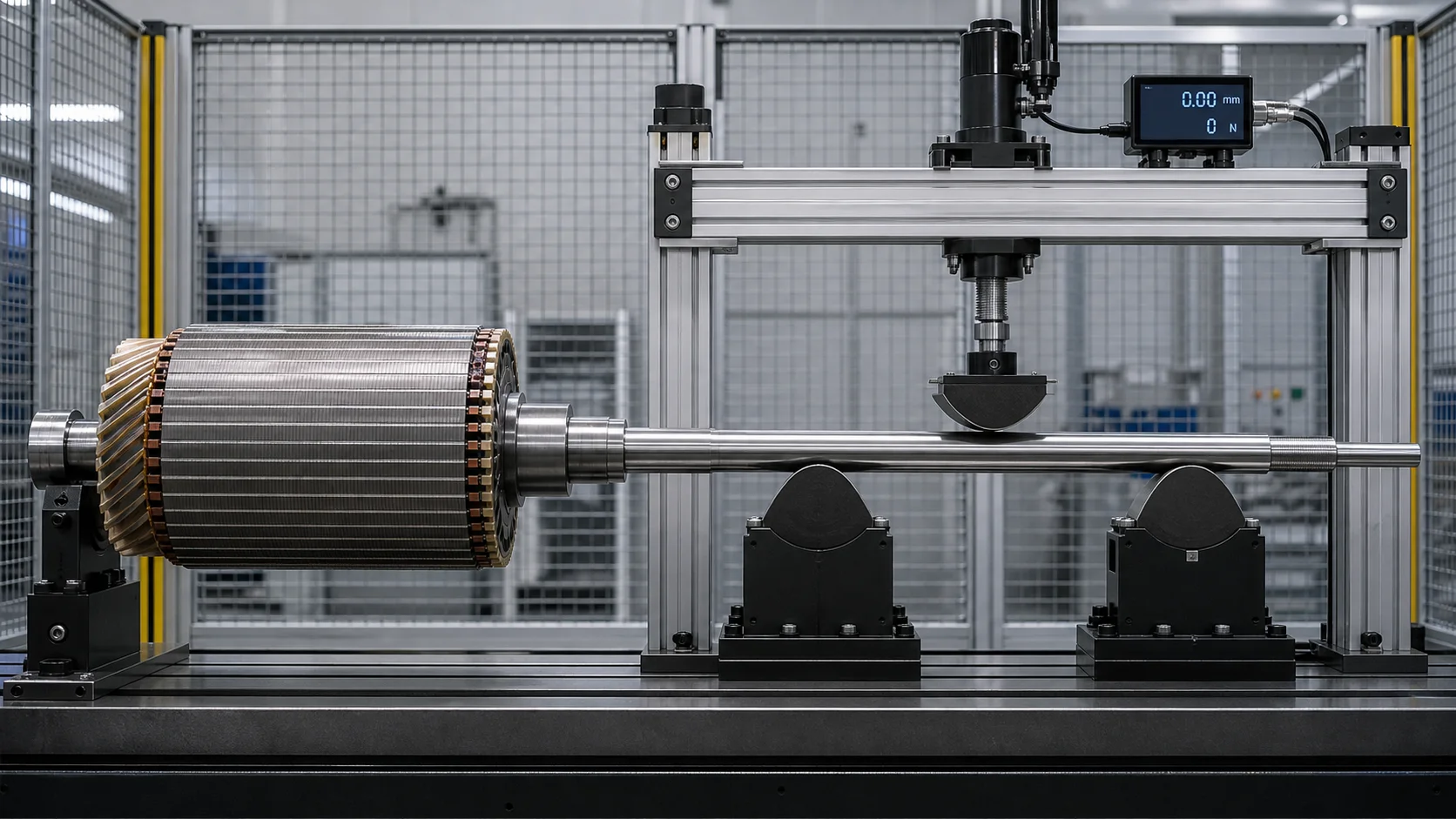
На этой концептуальной иллюстрации пакет роторов намеренно удерживается за пределами рамы пресса, а трехточечная нагрузка применяется только к открытому пролету вала.. Фактические координаты поддержки, радиус башмака и пределы силы требуют репрезентативных образцов.
Прямолинейность и баланс — разные вещи
Выпрямление и балансировка решают различные физические проблемы..
| Состояние | Измерение геометрии | Балансировочное измерение | Правильный ответ |
|---|---|---|---|
| Ось изогнутого вала | Обнаруживает взаимосвязь биения шейки/вала/сердечника | Может появиться как сигнал вибрации или дисбаланса, зависящий от скорости. | Правильная геометрия, если ротор находится в пределах утвержденного диапазона. |
| Массовый дисбаланс с прямыми шейками | Геометрию можно пройти | Определяет величину и угловое положение в одной или нескольких плоскостях. | Удалите/добавьте массу утвержденным методом балансировки. |
| Ошибка формы местного журнала | Обнаруживает проблему округлости/цилиндричности | Может нарушить поведение службы поддержки | Машинка или отказ; не рассматривать как глобальный изгиб |
| Эксцентриситет сердечника ротора относительно шейки | Биение сердечника отличается от оси шейки | Может способствовать дисбалансу и электромагнитным эффектам | Определить, является ли геометрия, ответственность за механическую обработку или сборку несет ответственность |
| Тепловой лук | Холодная геометрия может отличаться от рабочего состояния. | Может меняться в зависимости от скорости и температуры | Требуется проектирование теплового/рабочего состояния., не слепая холодная коррекция |
Руководство по балансировке Schenck поддерживает роторы на собственных шейках и измеряет дисбаланс в определенных плоскостях.. Это операция, отличная от восстановления изогнутой оси и применения коррекции пресса.. Балансировка не делает изогнутый ротор прямым., в то время как выпрямление не делает ротор сбалансированным.
Рекомендуемая последовательность
- установить этап сборки и данные функционального журнала;
- измерить освобожденную геометрию;
- выпрямлять только в пределах разрешенных зон и пределов материала;
- после выпуска перемерить всю геометрию;
- полная окончательная обработка там, где это запланировано;
- выполнить или проверить балансировку в необходимых плоскостях;
- полные окончательные испытания ротора и двигателя.
Если производственные ограничения требуют еще одного заказа, план проверки должен показать, как последующие операции влияют как на геометрию, так и на баланс..
Влияние поддержки управления и измерение выпуска
Масса ротора, Расстояние между опорами и состояние шейки влияют на наблюдаемую кривую. Ячейка должна определять:
- точное положение опор цапфы и профиль роликов;
- ориентация ротора и последовательность углового индексирования;
- контактное давление и защита поверхности;
- сила датчика или бесконтактное зазор;
- обработка провисания длинных или тяжелых роторов;
- стабилизация температуры;
- загруженное и выпущенное состояние измерения;
- корреляция с балансировочным станком и конечным датчиком двигателя.
Schenck документирует балансировку роторов на собственных шейках вала с использованием роликов или других опор для конкретного применения.. Передаваемый принцип заключается в том, что условие опоры является частью определения измерения.; конструкция и характеристики балансировочного станка не являются заявлениями о возможностях StraighteningTech..
Процесс выпрямления ротора с замкнутым контуром
1. Определите ротор
Выберите проверенный рецепт по номеру детали., конструкция ротора, этап сборки, состояние материала и редакция чертежа.
2. Осмотрите и очистите
Проверьте журналы, шпоночные пазы, концевые кольца, ламинирование, магниты/рукава, коммутатор, сокращение баланса и другие условия отклонения. Очистите одобренные опорные и измерительные направляющие..
3. Загрузка утвержденных журналов или данных процесса
Подтвердите ориентацию ротора, фиксация и угловая привязка без перетаскивания готовых поверхностей.
4. Измерьте все контролируемые пути
Поверните ротор и восстановите ось подшипника., открытая кривая вала и соотношение ротор-корпус, соответствующее чертежу. Маска разрывов.
5. Классифицировать отклонение
Отделение исправимого глобального изгиба от локальной ошибки формы., свободная сборка, эксцентриситет роторного пакета, электрическое повреждение или дисбаланс массы.
6. Выберите безопасный интервал коррекции
Используйте только утвержденные открытые зоны вала.. Подтвердить срок поддержки, направление коррекции, пределы силы/перемещения и зазор между роторным блоком.
7. Применить контролируемую коррекцию
Используйте проверенную модель упругого возврата, контролировать силу и смещение и останавливаться при аномальных сигнатурах.
8. Полностью отпустите и переизмерьте
Судите о ненагруженном роторе. Перепроверьте журналы, удлинения вала и дорожки корпуса ротора, поскольку одна коррекция может изменить несколько взаимосвязей.
9. Осмотреть и проложить маршрут
Выполнить необходимую поверхность, трескаться, электрические и монтажные проверки. Подготовьте соответствующие роторы для окончательной обработки или балансировки.; направить ненормальные детали на инженерную проверку.
10. Запишите результат
Сохранить идентификационные данные ротора, пересмотр рецепта, карты до/после, координаты коррекции, кривые сила-перемещение, сигналы тревоги и порядок действий, когда требуется прослеживаемость.
Предлагаемая конфигурация ячейки
Ячейка ротора для конкретного проекта может включать в себя:
- электромеханический или гидравлический пресс, выбранный на основе данных о силе образца;
- защищенные опорные ролики, центры или специальные приспособления для вращения;
- контактные или бесконтактные датчики для журналов, удлинители вала и корпус ротора;
- угловая индексация и маскирование объектов;
- сменные инструменты широкого радиуса с надежной настройкой;
- охранная автоматическая или операторская загрузка;
- сила, контроль смещения и рецептуры;
- повторное измерение в выпущенном состоянии;
- идентификация и отслеживаемость деталей;
- интерфейсы для завершения обработки, системы балансировки и качества.
Руководство по спискам Галдабини, цепь/вилка, Концепции портальной и роботизированной загрузки электрических роторов. Окончательный уровень автоматизации должен соответствовать реальной массе ротора., количество вариантов, чувствительность поверхности и производственный поток.
Образец испытаний и приемка
Матрица репрезентативной выборки должна охватывать:
- наименьший и наибольший диаметры вала и сердечника ротора;
- минимальная и максимальная длина и масса ротора;
- каждая конструкция и метод сборки ротора;
- сплошные и полые валы, где это применимо;
- состояние материала и термической обработки;
- минимальный и максимальный входящий изгиб;
- все открытые пролеты коррекции и запрещенные зоны;
- журналы до и после чистовой обработки;
- сердечник ротора, коммутатор, функции контактного кольца или энкодера;
- ранее сбалансированные и несбалансированные образцы;
- корреляция манометра клиента и балансировочного станка;
- поверхность, трескаться, электромонтажный и монтажный осмотр после исправления.
Используйте Руководство по испытаниям и приемке образцов выпрямления отделить осуществимость, ТОЛСТЫЙ, SAT и производственные возможности. Значение в машинном каталоге не является свидетельством конкретного семейства роторов..
Данные, необходимые для технического предложения
Пожалуйста, предоставьте:
- сборка ротора и чертежи валов;
- тип ротора, метод сборки и маршрут изготовления;
- материал, термическая обработка, твердость и состояние поверхности;
- варианты деталей, масса, длина и диаметр сердечника ротора;
- этап правки относительно сборки, механическая обработка и балансировка;
- рисование исходных данных и контролируемых характеристик биения/прямолинейности;
- Распределение входящих отклонений и известные искажения сборки;
- одобренные зоны поддержки и прессы;
- защищенные ламинаты, кольца, магниты, обмотки, шпоночные пазы и готовые посадки;
- счет коррекции, трескаться, электрические и поверхностные ограничения;
- балансировочные плоскости, метод и необходимая повторная проверка;
- манометр клиента и окончательные требования к испытаниям двигателя;
- автоматизация, требования к прослеживаемости и отчетности;
- репрезентативные образцы для испытаний.
Часто задаваемые вопросы
Может ли пресс давить на пластины ротора??
Не думайте так. Ламинирование, решётка клетки, концевые кольца, магниты и обмотки функциональны и чувствительны к повреждениям. Концепция по умолчанию удерживает их за пределами пути корректирующей нагрузки, если только разработчик ротора не утвердит специальное приспособление и проверку..
Стоит ли нам выпрямляться до или после балансировки??
Геометрия обычно должна быть установлена до окончательной балансировки.. Если ротор выпрямляется после балансировки, условие баланса необходимо перепроверить, поскольку ось вращения и соотношение масс могли измениться.
Может ли одна установка обрабатывать голые валы и роторы в сборе??
Возможно, но только по отдельным рецептам, поддерживает, сенсорные дорожки, карты инструментов и валидация. Полный ротор добавляет массу, жесткость, хрупкие черты и баланс ответственности.
Доказывает ли низкая вибрация, что ротор прямой??
Нет. Вибрация зависит от баланса, подшипники, опорная структура, электромагнитные силы, выравнивание, скорость и температура. Выпущенная геометрия должна быть измерена непосредственно в соответствии с требованиями чертежа..
Можно ли гарантировать точность модели САПР??
Нет. САПР определяет геометрию, но реальные образцы определяют существенный отклик, изгиб, вызванный сборкой, поддержка влияние, пружинение, поверхностный риск и балансирующая корреляция.
Создайте решение на основе всего ротора
Мы разрабатываем решения по выпрямлению роторов электродвигателей на стадии реальной сборки., опорная точка опорной шейки, защищенный роторный пакет, безопасные открытые зоны шахты, выпущенная геометрия и финальный маршрут балансировки. Оборудование может быть ручным., полуавтоматический или полностью автоматический, но логика коррекции должна оставаться специфичной для семейства роторов.
Как только будут даны ответы на вопросы, касающиеся процесса ротора электродвигателя, две страницы обычно сокращают короткий список: тот пошаговая инструкция по выбору выпрямителя и бюджетная картина для правильной машины.
Отправьте чертежи ротора и вала, маршрут сборки, входящие данные о биении, карта защищенных функций и метод балансировки. Затем мы можем определить план измерений, оснастка, корректирующий конверт, образец матрицы и отслеживаемый процесс приемки ротора вашего электродвигателя.