
Eixos de aço e peças do tipo barra cilíndrica podem desenvolver desvio radial e em arco após tratamento térmico, girando, moagem, armazenamento ou manuseio. Quando a peça contém vários diâmetros, o problema da correção não é simplesmente “endireitar a barra”: a máquina deve girar a peça em um ponto de referência acordado, meça apenas diâmetros aprovados, selecione um ou mais pontos de correção seguros e proteja o acabamento superficial especificado.
Esta solução proposta baseia-se 25 aço ou material equivalente, dureza HB 241–302, comprimentos de 183 para 720 mm e medindo diâmetros de 14 para 23.5 milímetros. O cliente registra um desvio máximo de entrada de 0.5 mm e um desvio alvo no diâmetro externo de 0.2 milímetros, com 1–5 pontos de endireitamento. Estas são entradas do projeto e devem estar correlacionadas com o desenho, dado, measuring positions and representative sample tests before they become machine acceptance guarantees. The underlying closed-loop principle is explained in como funciona o endireitamento automático do eixo.
Steel Shaft / Bar and Project Requirement
The customer data distinguishes measuring and non-measuring diameters, which indicates a rotating shaft/runout inspection problem rather than a simple full-length straightedge check. The final drawing must identify the functional datum, the exact measuring diameters and the features that may be used for support, rotation and pressing.
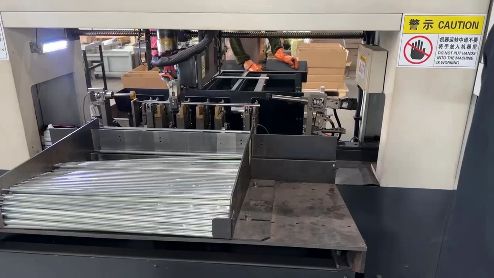
The public project video is titled as a tube straightening machine and shows a batch of cylindrical stock entering a multi-point measuring/press station. Because no end face is clearly visible, the footage does not prove whether the parts are solid bars or hollow tubes, nor does it prove that they are the stated 25 steel workpieces. This article therefore uses the customer specification to define a steel shaft/bar proposal and uses the video only as evidence of the general cylindrical-stock automation concept.
| Item do projeto | Entrada do cliente / Status |
|---|---|
| Peça de trabalho | Steel shaft / cylindrical bar-type part; final application to be confirmed |
| Material | 25 steel or equivalent; exact standard and certificate required |
| Rugosidade da superfície | Ra 1.25 μm |
| Dureza | HB 241–302 |
| Maximum Incoming Runout | 0.5 mm customer input |
| Target OD Runout | 0.2 mm customer requirement; datum and measuring method to be confirmed |
| Measuring Diameter | 14.0–23.5 mm |
| Other Diameter | 14.0–28.5 mm |
| Comprimento | 183–720 mm |
| Straightening Positions | 1–5 customer input; measuring/correction-point definition required |
| Método proposto | Automatic rotating measurement with point press-straightening and full remeasurement |
Radial Runout Is Defined by the Datum
Radial runout is the difference between the maximum and minimum probe readings while the workpiece rotates around a defined axis. If the shaft is supported on centers, two journals, rollers or another pair of diameters, each setup can produce a different result. The customer's 0.2 mm target must therefore be connected to the same datum used in the final inspection.
Straightness and runout are related but not interchangeable. A straight surface can still show runout if the datum is eccentric, and an apparently acceptable runout at one diameter may hide a bend at another axial position. The machine recipe should identify every required measuring point, its diameter, allowed probe contact arc and acceptance limit.
| Item de controle | Definição necessária |
|---|---|
| Dado | Centros, selected journals or specified reference diameters |
| Measuring Diameters | Exact positions within the stated 14–23.5 mm range |
| Incoming Limit | Maximum 0.5 mm de desvio; confirm whether this applies at every point |
| Alvo Final | 0.2 mm OD runout; customer requirement, not yet an accepted result |
| Straightening Positions | 1–5 approved axial press zones; not automatically identical to measuring points |
| Condição da superfície | Ra 1.25 μm and permitted support/probe/press contact areas |
| Inspeção Final | Same datum logic, rotation method and filtering as the agreed customer gauge |
Why This Shaft and Bar Family Is Difficult to Straighten
The length changes by almost four times and the diameter envelope includes both measuring and non-measuring sections. UM 720 mm part at the smaller diameter is much more flexible than a short part at the largest diameter. One fixed support span or press stroke cannot cover the family safely.
Hardness variation from HB 241 para 302 also changes springback and the amount of permanent correction produced by the same stroke. The Ra 1.25 μm surface must remain free from unacceptable probe scratches, support marks or press impressions. If the part contains shoulders, ranhuras, furos cruzados, threads or other transitions not listed in the current data, they may create stress concentrations and additional no-press zones.
| Desafio específico da peça de trabalho | Risco | Controle Necessário |
|---|---|---|
| 183–720 mm length range | Incorrect support span and unstable response | Posições e receitas de suporte específicas do modelo |
| Measuring vs non-measuring diameters | Probe on the wrong surface or datum mismatch | Drawing-based measuring-point definition and sensor travel |
| HB 241–302 hardness range | Variable springback, over-correction or crack risk | Adaptive stroke, conservative limits and batch/sample validation |
| Ra 1.25 μm surface | Contact marks or noisy measurement | Clean contoured supports, suitable probe force and approved contact zones |
| 1–5 correction positions | One press action changes neighboring points | Full-length measurement and validated correction sequence |
| Possible section transitions | Local stress concentration | No-press zones and suitable punch/support geometry |
| Competitor replacement request | Unsupported equivalence or price claim | Same-sample benchmark with agreed acceptance criteria |
Método de alisamento recomendado
Automatic point press-straightening is the preferred starting method because the part is measured by radial runout at several possible axial locations. The system rotates the shaft, identifies bend magnitude and angular direction, positions the workpiece or press at an approved correction point, applies controlled over-bending and then repeats the complete measurement.
A continuous roll straightener may be appropriate if the final workpiece is a constant-diameter bar with distributed curvature and a throughput requirement that favors through-feed processing. It is less suitable when the part has several diameters, protected finished surfaces or specific 1–5 press zones. If the actual part is hollow tube rather than solid shaft/bar, espessura da parede, inside diameter and collapse/ovality limits must be added before the method is selected. Para 12 m through-feed bar lines, veja o long steel bar roller straightening solução.
Processo de alisamento automático proposto
The related 16-second video shows cylindrical stock on a feed tray and a compact station with multiple supports, measuring components and a vertical press head. It demonstrates the material-flow and station concept, but it does not verify the workpiece material, construção sólida/oca, 0.5-para-0.2 resultado mm, HB range, cycle time or final project configuration.
| Etapa | Processo | Finalidade de Engenharia |
|---|---|---|
| 1 | Identificação de peças e seleção de receita | Match length, diâmetros, dado, points and limits |
| 2 | Feeding and singulation | Transfer one cylindrical part without scratching or double-feeding |
| 3 | Datum positioning and rotation | Establish a repeatable axis for runout measurement |
| 4 | Initial multi-point measurement | Record incoming runout at every required diameter |
| 5 | Validação de sinal e cálculo de curvatura | Separate real bend from roughness, eccentricity or feature effects |
| 6 | Correction-point and angular positioning | Align one of the approved 1–5 press zones with the ram |
| 7 | Controlled over-bending | Compensate springback within force/stroke limits |
| 8 | Nova medição completa | Evaluate all points after each correction |
| 9 | Correção adaptativa ou decisão NOK | Continue only inside the validated process window |
| 10 | Classificação final e registro de dados | Separate OK/NOK parts and retain required quality values |
Feeding and Model Control
Uma bandeja de preparação ou magazine pode apresentar peças cilíndricas à estação. Os trilhos guia, separadores e materiais de contato devem cobrir o envelope de 14–28,5 mm de diâmetro sem emperrar, misturar duas partes ou danificar o Ra 1.25 μm surface. Modelos mistos exigem verificação de receita por meio de ID de peça, verificação de comprimento, verificação do diâmetro ou um método poka-yoke equivalente.
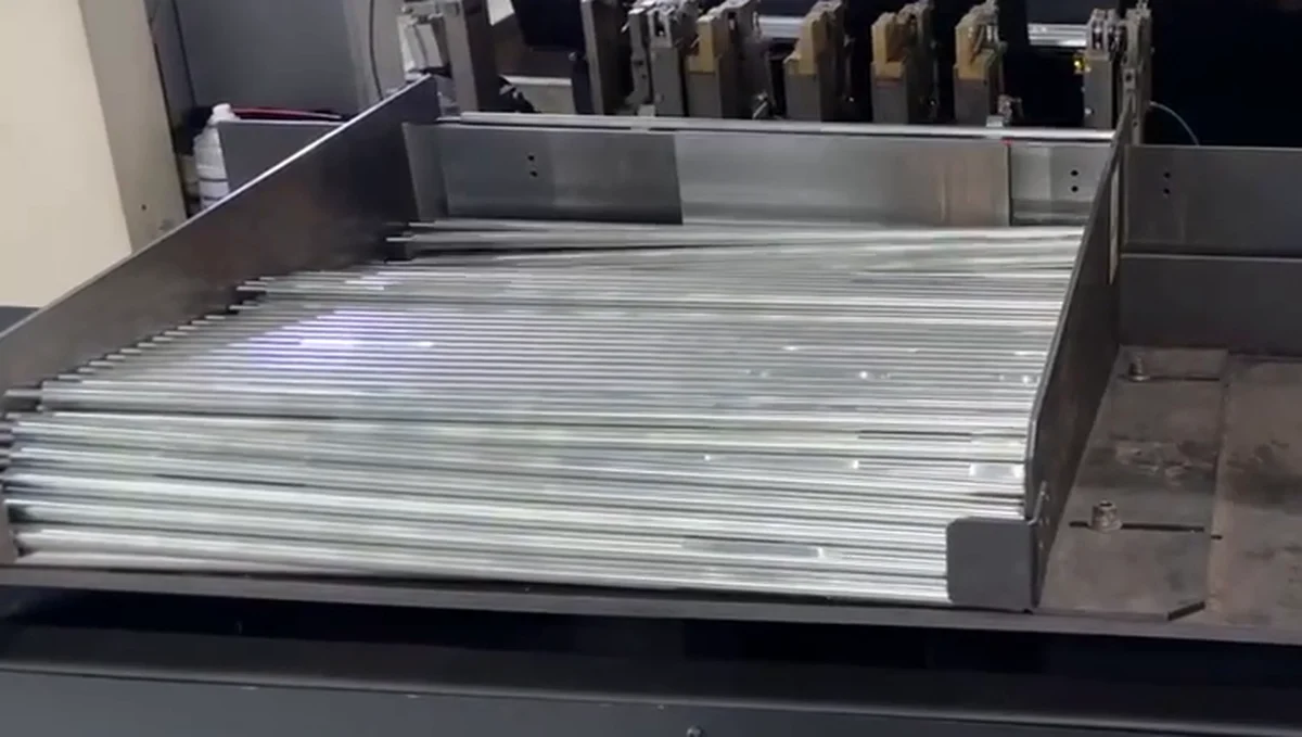
O vídeo não prova que a bandeja mostrada cobre todos os comprimentos e diâmetros declarados. O sistema de alimentação final deve ser validado usando o menor, mais longo, menores e maiores variantes reais.
Rotação e medição multiponto
A peça gira no ponto de referência acordado enquanto sondas de contato ou sensores a laser coletam desvios nos diâmetros de medição especificados. Força da sonda, sensor range and filtering should be selected for the surface and rotational speed. Surface roughness, roundness error or contamination must not be mistaken for shaft bend.

The 1–5 straightening positions should be mapped separately from measuring points. A probe may measure a functional journal while the safest press location lies on a neighboring, stronger section. The controller must use the drawing relationship between these points rather than assuming every measured maximum can be pressed directly.
Bend Calculation and Controlled Over-Bending
The control identifies the dominant bend vector and selects a correction sequence. Over-bending moves the part beyond the desired final position so elastic springback returns it closer to target. Initial stroke limits should be conservative, especially near the HB 302 end of the material range, and refined from the measured response of representative samples.
Where force measurement is available, force/displacement behavior can provide an additional abnormal-response limit. The system should stop if the response differs substantially from the validated recipe, the maximum correction count is reached or the part fails to converge safely.
Complete Remeasurement and Final Decision
After every press action, all required measuring points are checked again on the same datum. A local improvement is not enough if another diameter moves outside tolerance. The final OK decision requires the complete set of specified points to meet the customer criterion.
Quality records may include model ID, incoming and final runout, measuring-point results, correction positions/count, recipe version and final classification. The scope should match the customer's traceability requirement rather than adding data fields that will not be used.
Replacing Existing Equipment: Use a Controlled Benchmark
The customer is evaluating an alternative to existing straightening equipment. It is not technically sound to claim identical performance or a fixed two-thirds price reduction without comparing the same workpieces, método de medição, automation scope, tooling and lifecycle support.
| Item de referência | Required Comparison |
|---|---|
| Workpiece Set | Same shortest/longest, smallest/largest and worst-bend samples |
| Datum and Gauge | Mesmo suporte, rotação, probes and acceptance calculation |
| Qualidade | Final runout at every required point; surface and crack condition |
| Processo | Contagem de correção, tempo de ciclo, repeatability and NOK rate |
| Mudança | Ferramentas, recipe and operator time for all models |
| Automação | Alimentação, classificação, traceability and plant interfaces included in both scopes |
| Ownership Cost | Equipamento, ferramentas, instalação, treinamento, manutenção, spares and downtime assumptions |
| Aceitação | Written FAT/SAT criteria rather than an unsupported general equivalence statement |
Configuração de célula recomendada
| Módulo | Requisito proposto | Por que é necessário |
|---|---|---|
| Conceito de máquina | Automatic rotating point press-straightening cell | Closed-loop correction for multi-point shaft runout |
| Envelope da peça de trabalho | Length 183–720 mm; measuring OD 14–23.5 mm; other OD up to 28.5 milímetros | Covers the stated project family, sujeito a revisão de desenho |
| Sistema de medição | Multi-point contact or laser runout measurement | Match datum, surface and sensor-travel requirements |
| Rotação / Dado | Centros, rollers or journal supports selected from the drawing | Repeatable angular bend measurement |
| Unidade de alisamento | Fine-controlled servo/electromechanical/hydraulic press as sized | Manage springback across HB 241–302 |
| Supports and Punch | Ajustável, contornado, surface-protective tooling | Cover length/diameter range and protect Ra 1.25 μm surfaces |
| Estratégia de Controle | Receitas, bend vector, adaptive stroke and hard iteration limits | Correct 1–5 points without uncontrolled repeated pressing |
| Alimentação | Bandeja, magazine or manual loading based on validated takt and part mix | Match production flow without assuming unsupported automation |
| Dados de qualidade | Before/after results and correction history as required | Benchmarking, acceptance and traceability |
| Segurança | Guardando, intertravamentos, alarmes de sobrecarga e medição anormal | Protect operator, part and tooling |
Validação do projeto antes da cotação final
Amostras representativas devem cobrir o comprimento mínimo e máximo, all measuring-diameter variants, normal and maximum incoming runout, HB 241 and HB 302 material conditions, every relevant heat-treatment batch and all section transitions. The test report should record the datum, each measuring point, valor recebido, correction position/count, valor final, surface condition and cycle time.
The customer's inspection gauge and the machine should be correlated before the 0.2 mm value becomes an acceptance guarantee. If the actual workpiece is hollow or contains hidden features not shown in the current data, the drawing and sample review must revise the tooling and risk assessment before final machine selection.
Information Needed for a Steel Shaft and Bar Straightening Proposal
Please provide the final workpiece name and application, desenho, material standard and certificate, hardness and heat-treatment stage, all diameters and feature positions, center holes/journals, distribuição de runout de entrada, target at each measuring point, datum and gauge method, approved support/press zones, surface protection requirement, taxa alvo, volume anual, direção de carregamento e peças de amostra representativas.
These inputs allow the solution team to confirm whether the part is a solid shaft/bar or hollow tube, select the measuring and straightening method, size the force/stroke and tooling, and build an objective FAT/SAT benchmark.
Perguntas frequentes
Is the target 0.2 mm straightness or radial runout?
The current input calls it outside-diameter runout. The drawing must confirm the datum, measuring positions and rotation method. It should not be rewritten as straightness without that evidence.
Can the machine reduce maximum runout from 0.5 para 0.2 milímetros?
That is the project target, not yet a verified result. Feasibility depends on the datum, geometria, dureza, distribuição de curvatura, approved correction zones and sample-test response.
Can one machine handle lengths from 183 para 720 milímetros?
Potencialmente, if the support travel, posições de medição, press axis, feeding system and recipes cover the full range. The endpoint variants must be included in validation.
How is the Ra 1.25 μm surface protected?
The solution uses clean contoured supports, controlled probe force and drawing-approved contact/press zones. Surface inspection remains part of the sample-test acceptance plan.
Why are 1–5 straightening points important?
They indicate that different models or bend profiles may require different correction locations. The machine must remeasure all controlled diameters after each correction because improving one point can change another.
Does the video prove these are solid 25 steel shafts?
Não. It shows cylindrical stock and a straightening station, but the ends and material are not identifiable. The article's shaft/bar specification comes from the project data, not from a visual guess about the video.
Can this equipment be presented as equal to an existing competitor at a fixed lower price?
Only after a controlled same-sample benchmark and a comparable commercial scope. Qualidade, tempo de ciclo, ferramentas, automação, service and lifecycle cost must be compared using written acceptance criteria.
Conclusão
This steel shaft/bar project is defined by multi-diameter runout measurement, 1–5 controlled correction positions, HB 241–302 springback and protection of the Ra 1.25 μm surface. A reliable solution must measure the complete part on the functional datum, correct only approved zones and verify every point after each press action.
For a steel shaft and bar application like this one, procurement teams usually pair the manual vs automatic selection logic with the Caso ROI para endireitamento automático before shortlisting vendors.
Envie seus desenhos, material/hardness certificates, dados de runout de entrada, 0.2 definição de aceitação mm, part mix and sample information for a feasibility and benchmark review. Final performance should be agreed through objective FAT/SAT criteria rather than unverified equivalence or price statements.